
During the creation and development of this book, the USB has progressed, since its introduction in 1996, through three iterations, and was scheduled for a fourth revision in 2019. In essence, the USB connection is a concept expressed as a written standard that describes an electro-mechanical and software protocol system through which a host computer is automatically interfaced to peripheral devices when a standardized electrical cable is plugged into each unit.
In USB 2.0 cables there are four wires for electrical transmissions and power delivery. Digital information is transferred on a twisted pair of wires known as D+ and D- (color-coded as white and green, respectively). A nominal 5V, 400 mA power is carried on the cable’s red wire, with the remaining black serving as a ground. (Occasionally, orange and white are powered with green and blue data lines.)
USB 3.0–compliant cables have an additional two insulated twisted-pair data lines in addition to the four-wire 2.0 specifications to aid in increasing the data-transfer capability of the newer specification.
Information in digital systems is carried by the high-frequency on–off binary nature of the encoding. The digital-based USB communication system is very dependable and not only connects and interfaces the host and peripheral devices but also transmits data, usually without error. However, audio and high-sensitivity electronic measurements have been reported to be compromised by high-frequency noise on the USB connection.1 An experimental noise-reduction filtering system and its effects are detailed in the UK website, and numerous USB audio noise-suppression devices and methods are available commercially. An in-depth white paper is available as a PDF from the Wurth Elektronik company entitled “ANP024 The USB Interface from EMC Point of View.”2 The thirteen-page paper fully describes the USB standard, hardware, electrical specifications, topology, and protocols for the system. The paper discusses in detail the electromagnetic compatibility (EMC) of the components and systems of the USB communications connections and details the techniques and components that can be used for controlling signals and noise on the link with various USB filters. A kit is available from the Wurth company for developing a USB EMC filter to suit a particular experimental application.
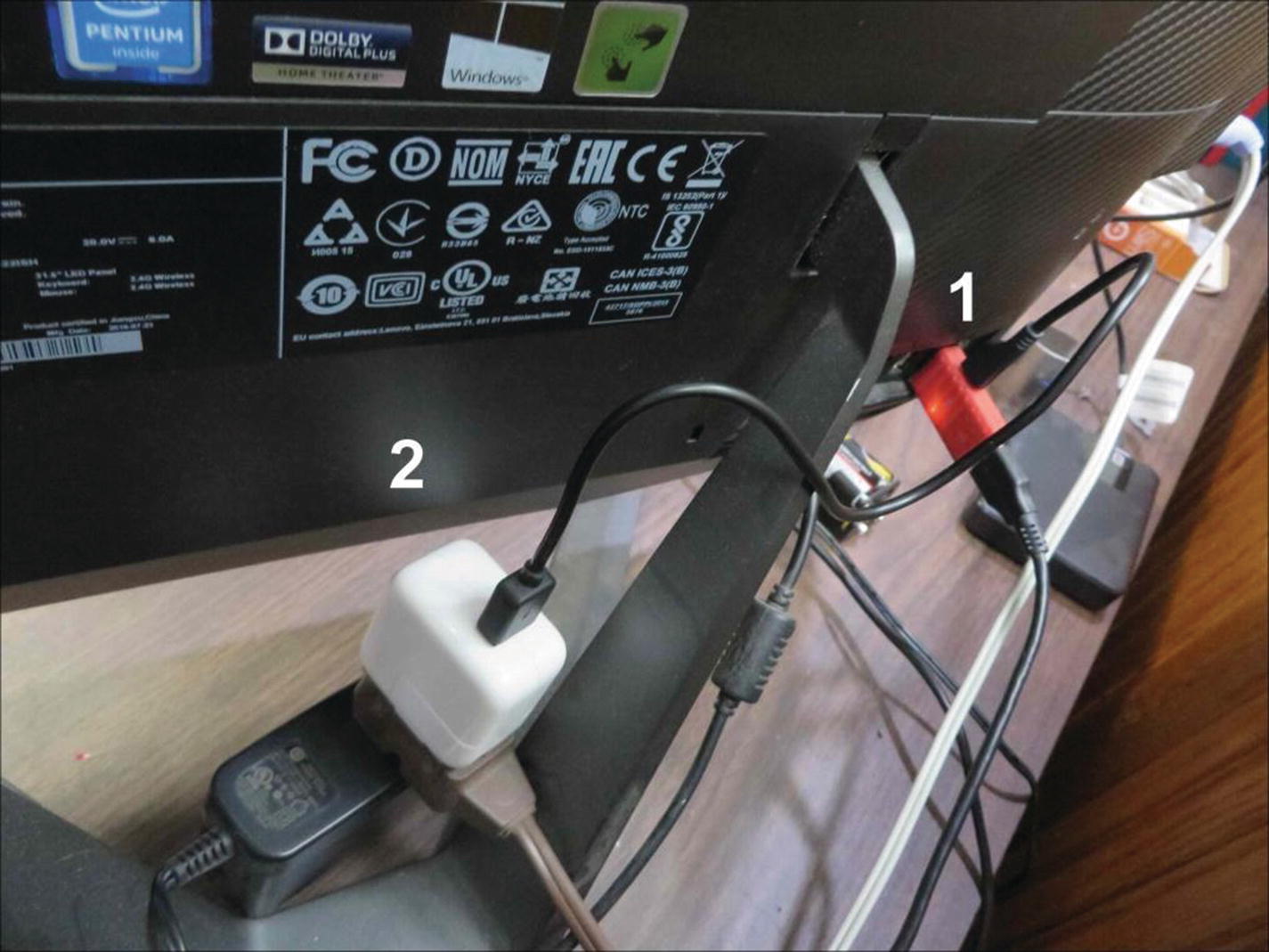
The iDefender and a 5V auxiliary power supply installation on a desktop host computer USB port
Item 1 in Figure 8-1 is the isolation device that is plugged directly into the host bus port. The glow on the bottom portion of the red case is from the pilot light for the auxiliary 5V supply that is powering the downstream devices on the bus. Item 2, the white rectangular box, is a 5V supply powering the positive and ground wires in the USB cable connected to the iDefender. The USB power lines in the cables connected to the iDefender are thus drawing current from the line or mains supply and are bypassing the host computer’s internal supply and wiring buried inside the electromagnetic wave–filled environment within the host’s grounded metal case.
System noise reduction can be increased through electromagnetic compatibility considerations that include high-quality shielded USB cables fitted with ferrite bead chokes and well-regulated external bus power sources. For host computers with multiple USB ports, test each one with a high-scale expansion strip chart recorder display to find the connection with the lowest level of spurious signals, spiking, and noise.
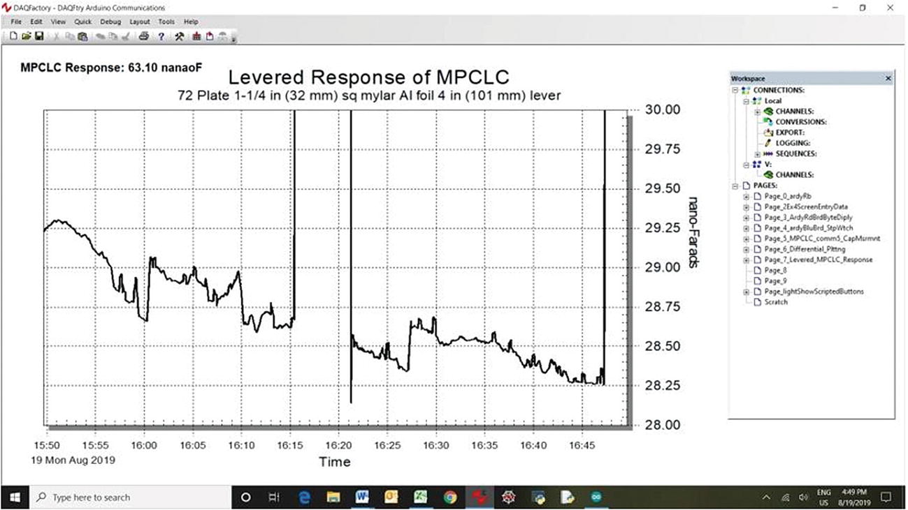
Typical Baseline Noise and Large Signal Distortions

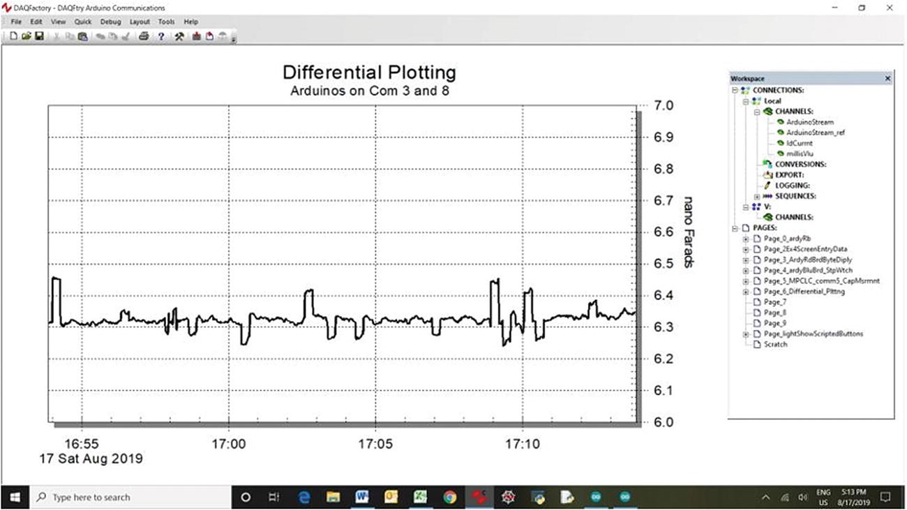
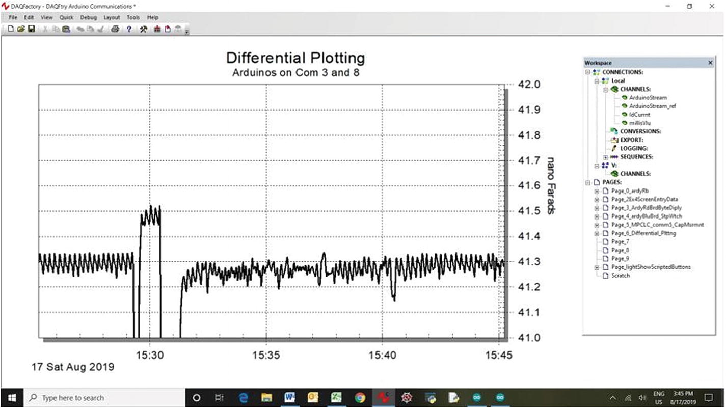
Ringing at 8:30

Ringing at 6:05

Commercially Available Noise-Reduction Devices
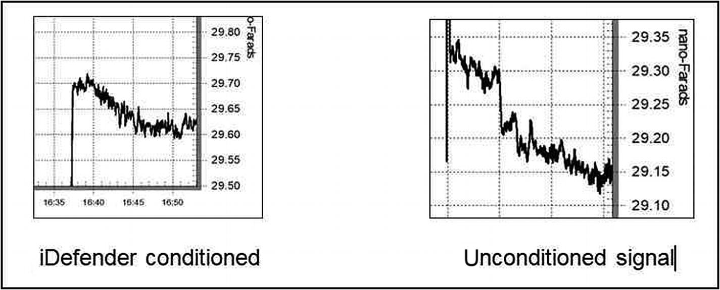
Noise reduction by iDefender 3.0 USB filter
Discussion
The USB connection is a two-way transmission system that is usually embedded in a noisy environment of high-frequency, high-intensity electromagnetic radiation within the host computer metal case. In the author’s Windows system, the Device Manager USB entry indicates the presence of eleven super-speed hubs, regular hubs, composite devices, mass-storage devices, and root-hub controllers. Some of these USB devices are running continuously at kHz clock frequencies, and external peripherals such as keyboards, mice, thumb drives, external hard drives, and audio-visual displays create substantial activity on the bus.
Where possible, bus noise can be lowered by reducing or eliminating other devices on the bus being used to communicate with high-sensitivity testing equipment.
Audio-improvement discussion groups suggest the use of only one mains power outlet that may be connected to a power bar to supply all of the components in an audio system. The use of a single power outlet minimizes the possibility of a ground loop’s developing.
Figure 8-8 indicates that the iFi iDefender 3.0 virtually halves the baseline noise seen on the author’s capacitance measurement experiments. High-quality USB cables equipped with ferrite “beads,” heavy braided-metal mesh EMI insulation and inner foil-wrapped wiring should be used for all high-sensitivity instrumentation.
Filters, quality cabling, ground-loop prevention, and the elimination of other devices on the bus in use can substantially reduce the noise on the USB to the point at which experiments at higher sensitivities can be carried out with reasonable reproducibility.
Summary
Spiking and ringing are the two main interferences encountered by the author when using the USB for high-sensitivity experimental measurements.
Ground loops, USB power, and high-frequency bus noise are suggested as the sources of the interference.
Separate power supplies, commercial USB filters, and using only one mains outlet with a power bar are suggested as methods to lower the interference.