Chapter 5. Deployment Blueprint
In this chapter, we’ll cover some of the decision points you’ll want to go through in order to optimize the design of your XenServer deployment. While it might be tempting to call these “best practices,” it would be more accurate to describe them as a simple decision tree. The core topics covered are storage and networking as they relate to creating a stable deployment with predictable performance.
Start with Storage
All VMs will need their disks to be stored someplace, and it’s important in your blueprint to decide how the VM interacts with the resources you provide. In Chapter 4, we covered pools versus standalone hosts, shared versus local storage, defining an input/output (I/O) envelope, and designing for failure.
Each of these items has storage at its core, so in the following sections, we’ll provide a basic decision matrix.
Local Versus Shared Storage
If you use local storage in a resource pool, all I/O associated with those VMs is local to the host. This can be beneficial if the VMs have compatible I/O requirements. One of the drawbacks to local storage is that VM migration will be more resource intensive, slower, and have a greater user impact than with shared storage due to the usage of storage migration. During storage migration, the underlying disk is copied from the source storage to destination storage, and this copy occurs over a management network. Because the primary management network is used for all pool operations, the copy operation can also impose a performance penalty on VM provisioning and pool maintenance.
Another form of VM agility that is impacted by local storage is XenServer HA, or host failure protection. Because XenServer HA requires heartbeat storage and an agile VM, the use of local storage will prevent a VM from being restarted in the event of host failure.
NFS Versus iSCSI
Within the storage community, there has been a long debate over which is more efficient, Network File System (NFS) or Internet Small Computer System Interface (iSCSI). In this book, we’re not going to enter that debate, but it is important to understand how XenServer uses storage with each of these technologies. The first, and arguably most important, item to understand is that from a XenServer perspective, NFS is always thinly provisioned, while iSCSI is always thick provisioned. This means that if you have a VM with a 20 GB disk with 12GB used, on NFS you will only use 12 GB while on iSCSI you will always consume 20 GB.
This point becomes even more important as you include the concept of snapshots because they, too, will be provisioned with the underlying storage. In other words, if we have our original VM and then take a snapshot that results in an additional 1 GB of disk used, on NFS, we’ll only be using 13 GB, while on iSCSI, we’ll have 40 GB consumed. Factoring in snapshot usage can have a significant impact on the choice of storage interface, but it’s not the only one.
Fibre Channel and HBAs
Fibre Channel (FC) describes both the technology and protocol (based on SCSI) for high-speed storage. As the name indicates, the technology utilizes host bus adapter (HBA) cards that utilize fibre connections: connecting to a specialized switch or directly into the controller for the storage. From a XenServer perspective, storage operations involving HBAs will be very similar to those of iSCSI-based storage. The primary difference is in the connection and transport, and where we describe iSCSI operations, limitations, and best practices, those same attributes can be applied to Fibre Channel or HBA-based storage.
Converged Network Adapters
When we sat down to write this book, converged network adapters (CNAs) were quite popular because they allow optimized storage traffic to traverse over Ethernet. With XenServer 6.5, few CNAs are officially supported; and in many cases where used, it is generally the Ethernet capabilities that can be leveraged. Of note, hardware FCoE support was added in XenServer 6.5 service pack 1 with a limited set of hardware vendors. As an administrator, make certain to cross reference fibre-based storage solutions with the XenServer hardware compatibility list for compatibility.
Multipath Configurations
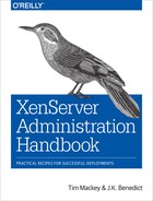
In production deployments, having minimal single points of failure is desired. If NFS is used as the storage solution, this is accomplished by bonding multiple storage network interface controllers (NICs) to form a redundant link to the NFS server. More on bonding can be found in the section “Define Network Topologies”. While it is possible to use network bonds with iSCSI, a far more common scenario is to use multiple physical network paths to multiple storage controllers. Such a configuration ensures that multiple independent interfaces to the storage can be maintained. Figure 5-1 shows how a single session established from a host to a storage target operates. In this scenario, network failure would result in loss of session and by extension loss of the underlying storage for all VMs using the storage target. By contrast, Figure 5-2 shows that loss of a single session in a multipath configuration will result in failover to remaining sessions.
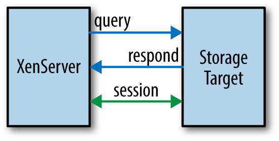
Figure 5-1. Without multipathing: single session, single point of failure
From a blueprint perspective, it’s important to understand how each path is maintained within XenServer. As a refresher, for block storage, a storage repository (SR) is the logical unit number (LUN) on which the VM disks will be stored. There is a physical block device (PBD) interface between the SR and the storage manager.
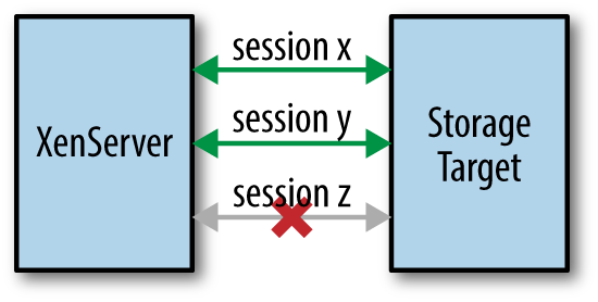
Figure 5-2. Multipathing: sessions X & Y sustain storage while session Z is down
This means that for each path in a multipath configuration, there will be one PBD to plug into the storage manager. Because the length of time required to plug a given interface in is a function of storage controller response time, having a large number of LUNs per host in a multipath configuration can result in extended host restart times. This presents a natural trade-off between potential increased system redundancy, input/output per second (IOPS) per controller, IOPS per LUN, and host recovery time.
Because the goal of a multipath configuration is redundancy, proper design requires redundant physical infrastructure. This can include backplanes, switches, fabric extenders, and will often include tuning the storage per vendor best practices.
All trade-offs, tuning decisions, and redundancy assumptions should be defined at the design phase and documented. In Example 5-1, we see that procedure to enable multipath storage on a host, and the reader should note that this operation requires the host to be disabled, which will evacuate or stop all running VMs.
Example 5-1. Enabling multipath configurations on XenServer
# xe host-disable host=[hostname]
# xe host-param-set other-config:multipathing=true
      host=[host uuid]
# xe host-param-set other-config:multipathhandle=dmp
      uuid=[host uuid]
# xe host-enable host=[hostname]
Define Network Topologies
Within a XenServer environment, there are several potential network topologies, but all require that hosts within a resource pool have identical configurations. An identical configuration will be one with the following attributes:
- Consistent enumeration of NICs across reboots. If the host BIOS changes the device order for NICs between two reboots, this can cause significant issues to XenServer.
- Consistent network interfaces between hosts. This is best explained with an example. Regardless of which physical NIC the BIOS assigns to “eth0” in a given host, “eth0” for all hosts identifies a management network that will utilize the same switch. The same requirement must be met for all interfaces, and a consistent interface is one which is identical in all parameters including frame rate and size.
- Framing must be consistent within a network interface. This is also best explained with an example. If the frame size for “eth2” is Jumbo, then all host network interfaces within the “eth2” network must be set to “Jumbo.”
- Network speed must be consistent within a network interface. It is not possible to mix 1 Gb and 10 Gb NICs within the same network, and the same extends to duplex settings.
- All networks with assigned IPs (management interfaces) must be within the same broadcast domain. While it may be possible to have management traffic span network segments, doing so could result in inconsistent state between member servers in a pool, and not all management functions are guaranteed to function.
- All networks with assigned IPs must have single-digit latency or better.
- When Virtual LAN Segments (VLANs) are used for management interfaces, the network switch port must be configured to provide a default VLAN that is configured as “not-tagged” by the switch.
Bonding and LACP
NIC bonding, also referred to as “teaming,” is a method by which two or more NICs are joined to form a logical NIC. Bonded NICs provide a redundant connection and in certain configurations can increase aggregate throughput. XenServer supports three distinct bonding modes: active-backup, balance-slb, and Link Aggregation Control Protocol (LACP).
active-backup bonding
With an active-backup bond, one interface in the bond is designated as active, and all other interfaces are backups. In the event the link is lost for the active interface, a backup with a link will be selected to replace it. Figure 5-3 shows a bonded network with eth0 and eth1 forming the bond where eth1 is the backup. No traffic flows over eth1 until the connection to eth0 fails, at which point the bond automatically operates, as shown in Figure 5-4.
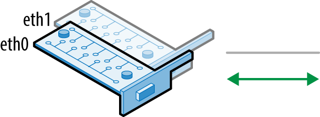
Figure 5-3. eth0 active, with eth1 ready as a backup
With an active-backup bond, it is assumed that redundant network paths exist so when a backup is selected the network will use Gratuitous Address Resolution Protocol (GARP) for all interfaces; including any VMs on the network.
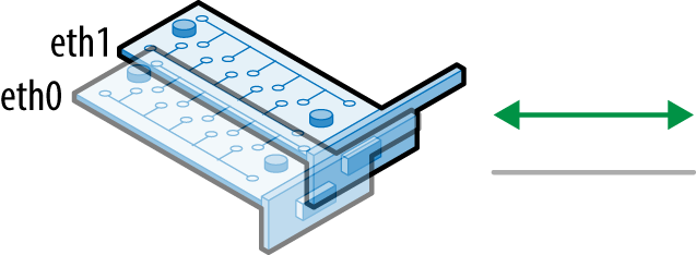
Figure 5-4. eth1 active, taking over responsibilities for ETH0
This bonding mode is supported for both Linux bridge and Open vSwitch based bonds and assumes stacked switches (Example 5-2).
Example 5-2. Create active-backup bond
# xe bond-create mode=active-backup network-uuid=<network-uuid>
  pif-uuids=<pif-uuids>
balance-slb bonding
With balance-slb bonding, a source-load-balancing active bond is created with balanced traffic. This means that all interfaces in the bond are used, with traffic balanced between the interfaces based on load and source VM MAC address. Balancing based on source media access control (MAC) address implies that transmit and receive traffic for a given VM will always occur over the same path. Example 5-3 shows the command to create a balance-slb bond.
The traffic flow is rebalanced every 10 seconds by default, but this can be defined when the bond is created. When traffic is rebalanced, the physical route to a given VM through the network bond may change. balance-slb uses the standard Linux balance-alb algorithm at its core, which requires the network driver support dynamic rewrite of the MAC address in order to avoid Address Resolution Protocol (ARP)/GARP during rebalancing. This bonding mode is supported for both Linux bridge and Open Virtual Switch based bonds and assumes stacked switches. Note that if network monitoring is done at the physical interface layer, data can be lost during a balancing event.
Example 5-3. Create balance-slb bond
# xe bond-create mode=balance-slb network-uuid=<network-uuid>
  pif-uuids=<pif-uuids>
LACP bonds
LACP bonds are created to support link aggregation or 802.3ad (802.1AX-2008, as defined by the IEEE at http://www.ieee802.org/3/ad/). LACP is only supported by the Open Virtual Switch and requires physical switches configured for LACP using LACP data units (LACPDU). Cisco EtherChannel and Port Aggregation Protocol (PAgP) are not supported. LACP can be configured for up to four interfaces per bond. LACP determines traffic flow by default based on a hash of the source and destination IP, TCP/UDP port, and source MAC address. Example 5-4 shows the command to create a LACP bond.
Due to the increased parameters in the hash when compared to balance-slb, LACP bonds can result in transmit and receive traffic to a given VM following different paths. Because destination IP and port are used in the hash, LACP bonds may provide limited throughput gains when traffic is occurring to a single destination.
An example of such a configuration would be use of LACP for storage traffic where the storage solution is an NFS server, or an iSCSI controller with a single path. In both configurations, the hash will compute to bind traffic to a single member NIC within the bond, which will result in LACP behaving as an active-backup bond.
Example 5-4. Create LACP bond
# xe bond-create mode=lacp network-uuid=<network-uuid>
  pif-uuids=<pif-uuids>
Jumbo Frames
Jumbo frames are Ethernet frames that carry more than 1,500 bytes of payload, or more than the standard maximum transmission unit (MTU). While no standards exist to define jumbo frames, storage and hardware vendors offer end-to-end support for Ethernet frames, which can carry up to 9,000 bytes of payload. It’s important to understand that with a lack of standard, the precise MTU value for a given network device can vary by vendor. Ensuring compatible MTU values is crucial to realizing the performance benefits jumbo frames can offer to storage traffic. If the MTU in any device in the data path is smaller than either the source or destination device, packet fragmentation will result, and the resultant retransmissions will impact overall throughput.
XenServer defines a jumbo frame using a MTU of 9,000, and jumbo frames are only supported for use on storage networks. Example 5-5 shows the command line operations to perform in order to ensure the MTU is correct on all elements of the physical interface.
Example 5-5. Verify MTU on all networks
# xe pif-list params=uuid,network-name-label,MTU
# xe network-list params=uuid,name-label,MTU