
CHAPTER 3
ExploroBot—Build It
Before you begin building the ExploroBot, take a look at Figure 3-1. Remember, this is just one possible version of the ExploroBot. Some of you might choose to design and build your own version without going through this chapter, but for those who would like to build the one pictured, I have a few suggestions.
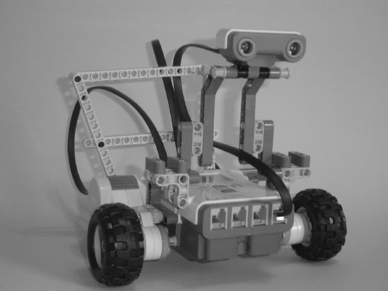
Figure 3-1. Evan's version of the ExploroBot
Never Be Afraid to Experiment
I've chosen to include actual pictures of the construction of the ExploroBot. I've tried to provide enough detail in each figure for you to discern what parts are used and where those parts are placed. If you find that what you're holding in your hands doesn't quite look like the picture, do the following:
- Take a deep breath.
- Remember this is supposed to be fun.
- Go back to the previous step and confirm you've made it that far.
- Look at the current step, and examine the figure's details for clues to where components should be placed. Things like counting holes to determine where two or more parts connect is useful. So is skipping ahead a few figures to try and see the parts from another angle.
- When in doubt, take your best guess and move forward.
If you do hit a roadblock and just can't figure out how to move forward, try taking a look at the next few steps. Sometimes another figure will show the ExploroBot from a different angle and you'll see the solution. Enjoy the building process and realize that if your final bot doesn't look exactly like the one in this chapter, that's okay. Remember: getting the bot to work and solving the challenge is your main goal.
Note If you modify or try to create your own version of the ExploroBot (or any other bot in this book), please take a picture and e-mail it to me. I would enjoy seeing your final bot in action. I've included my e-mail address in the Introduction.
And now, on to the construction of the ExploroBot!
Step by Step
I'm going to break the ExploroBot into four sections. The first section will be the Ultrasonic Sensor and the "neck" used to support it. The second section will be the body, including the two motors and two wheels. The third section will be the rear-wheel assembly and the frame used to keep the cables tidy. You'll finally assemble the ExploroBot in the fourth section using the head/neck, body/motors, and frame/rear-wheel subcomponents.
For each section, I'm simply going to jump from figure to figure. I'll make comments where I feel a tricky area might exist or where I feel you need to be made aware of a special assembly instruction.
Pay special attention to those figures showing the individual parts lying unassembled. These will help you to determine what parts to locate for upcoming assembly figures.
Here we go . . .
First Section: Ultrasonic Sensor and Neck
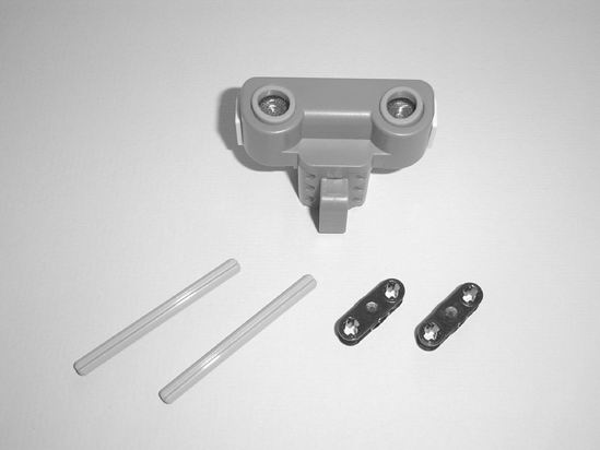
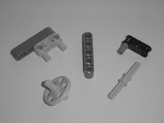
Starting with Figure 3-2 and continuing through Figure 3-9, you'll be assembling the ExploroBot's head and neck. Take a look at Figure 3-2 and Figure 3-4. These are the figures that show the majority of the parts you'll be using in this section.
 |
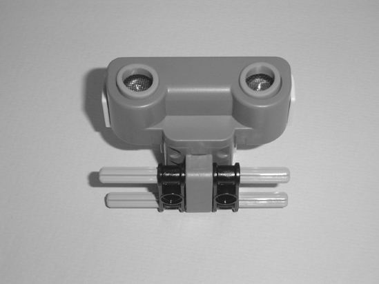 |
Figure 3-2. These are the parts you'll need for the ExploroBot's head. |
Figure 3-3. The fully assembled ExploroBot head—set this aside for now |
 |
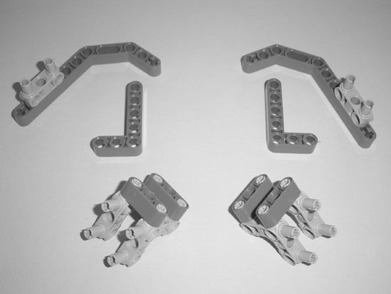 |
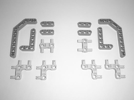
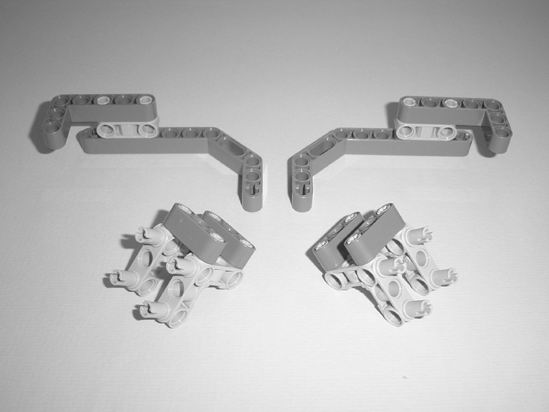
Figure 3-4. Parts for the left and right sides of the neck that will hold the ExploroBot's head |
Figure 3-5. Partial assembly of the left and right sides of the neck |
 |
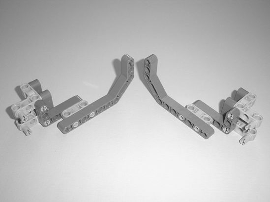 |
Figure 3-6. Place the L-shaped beams. |
Figure 3-7. The fully assembled left and right sides of the neck |
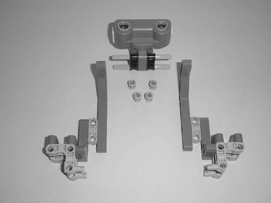
Figure 3-8. The left and right sides of the neck, ExploroBot's head, and four round connecting pins
Note What I call a "round connecting pin" is also called by its official Lego name: Part # 3713 Technic Bush. Why do I tell you this? Because I want you to be aware that Lego gives a unique part number to every component it sells. Also, because this is where I tell you that I'm going to avoid using the official part numbers unless absolutely necessary. If you're unable to determine the identity of a component from a figure, take a look at the next figure or two. You'll most likely be able to determine what the component is by seeing it from a different angle or by seeing it where it's placed.
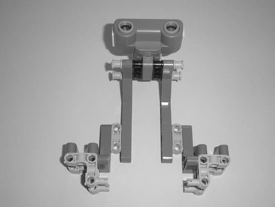
Figure 3-9. The fully assembled ExploroBot head and neck—set this aside for now.
It's time for a quick check here. Take a look at your ExploroBot head and neck. Does it look like the one shown in Figure 3-9? If not, try and identify where the difference is and go back to the figures showing the assembly. If the difference is extremely obvious, spend a few minutes looking at the parts and you'll find the mistake. When working with such small parts, it's not uncommon to connect a part in reverse or upside down—I do it all the time.
When you're satisfied with the ExploroBot head and neck assembly, set it aside for now. We'll come back to it after you've completed the main body and rear-wheel sections.
Second Section: Bot Body and Motors
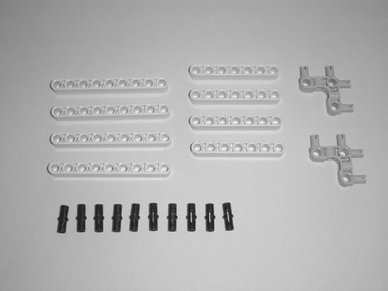
In this section, you're going to build the ExploroBot's main body and its two motor/wheel combinations. Take a quick look at Figure 3-10 and Figure 3-12. These two figures show the majority of the parts you'll be using in this section.
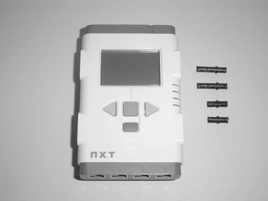
Figure 3-10. The body will be made of the Intelligent Brick and a few connectors.
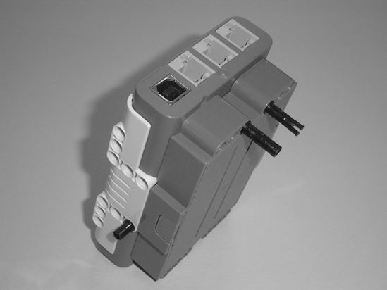
Figure 3-11. Left and right side views of the Intelligent Brick and placement of the connectors
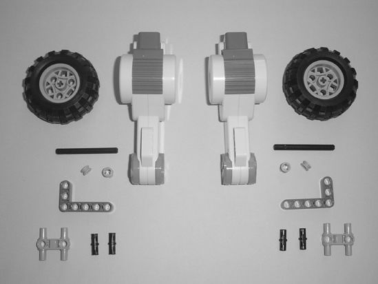
Figure 3-12. Components for the left and right side motor/wheel combinations
Note In Figure 3-12, you can determine the length of the black rod by comparing it to the length of the L-shaped beam. Please also note that in the figure there are two round connector pins and two half-thickness round connector pins. These two half-thickness pins are shown standing up so you can see the thin groove. These are used as spacers to keep the rubber wheels from touching the orange motor face. Figure 3-13 shows the proper assembly in more detail.
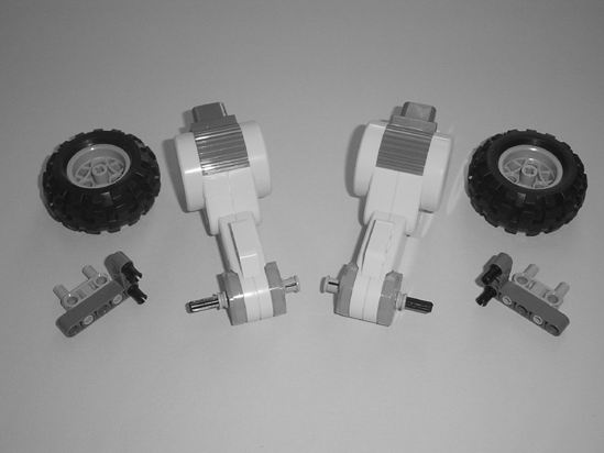
Figure 3-13. Partial assembly of the left and right motor/wheel combinations
 |
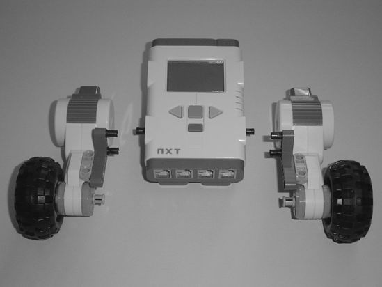 |
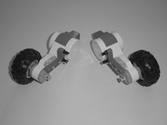
Figure 3-14. The fully assembled motor/wheel combinations |
Figure 3-15. The Intelligent Brick and the motor/wheel combinations before assembly |
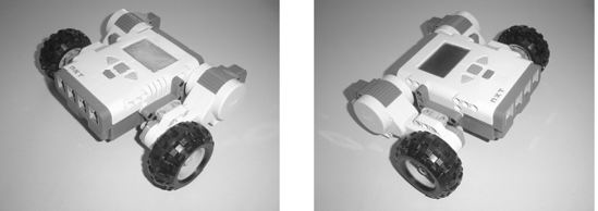
Figure 3-16. Components for the left and right side motor/wheel combinations
Okay, it's time again to check your work. Compare your ExploroBot body with the one shown in Figure 3-16. You can use Figure 3-16 to compare things such as the location of the black connectors in the L-shaped beams to make sure you've got the motor/wheel combinations located properly.
Again, the key here is to look for any major differences between your ExploroBot's body and the one shown in Figure 3-16. If you find any differences, just go back and examine the figures carefully where the mistake appears to have been made. If necessary, take the assembly apart and start over. You've got plenty of time and you're having fun, right?
Are you happy with the ExploroBot's body? Congratulations! You're half done with the ExploroBot. We're going to move on to the third section, which is a little longer and a little more complex due to the number of parts being used. Just take your time on this section and enjoy the building process. Remember my advice—if you get stuck, just take a deep breath and remind yourself that this is fun. You can't make a mistake because you can always start over—no harm done!
Now let's finish the ExploroBot's rear-wheel section and then get this bot assembled . . .
Third Section: Rear-Wheel Assembly and Frame
There's a lot to build in this section. First you're going to build a small frame that will help you to control the cables you'll install in the fourth section. Then you're going to build a small rear-wheel and a base to hold the rear-wheel. This base has a lot of parts, but you'll find that it helps to strengthen the bot and reinforce the rear-wheel.
Take a quick look at Figure 3-17, Figure 3-20, and Figure 3-25. These figures show the majority of the parts you'll be using in this section, but in some later figures you'll notice I've added some new parts. My best advice is to pull out the parts you see in the three figures I've mentioned. You'll know when I've added some new parts because you'll have used all the previous ones you set aside! And again . . . when in doubt, just pause and examine the figures more closely. I've made sure to include enough detail for you to figure out what parts are being added to the mix.
Now, let's start with Figure 3-17 and the cable frame.
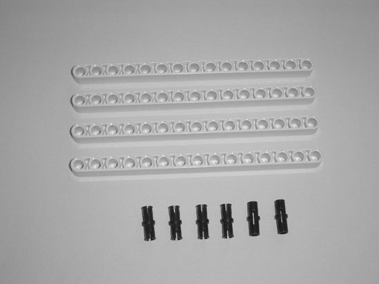
Figure 3-17. Parts needed for the ExploroBot's rear frame, used to keep cables untangled
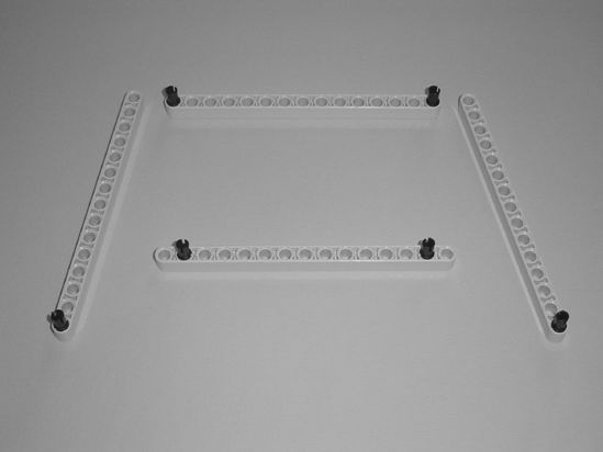
Figure 3-18. Partial assembly of the cable frame
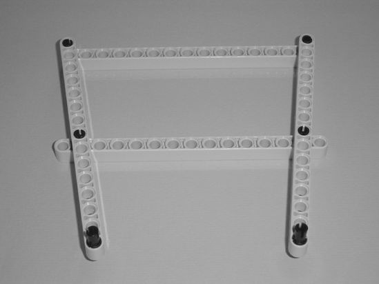
Figure 3-19. The final cable frame assembly—set this aside for now
Next, Figure 3-20 shows the start of the rear-wheel.
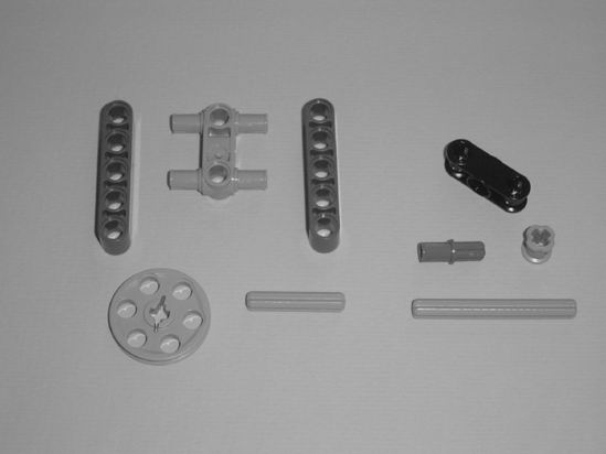
Figure 3-20. These are the parts for creating the rear-wheel.
 |
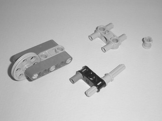 |
Figure 3-21. It's not quite a rear-wheel yet, but keep going . . . |
Figure 3-22. The rear-wheel is starting to come together . . . |
Note In Figure 3-22 you'll notice that I've added two new parts that weren't seen in Figure 3-20. This will happen again in later figures, so be on the lookout for it. As I mentioned, if you set out the parts that you need for each section, when I add parts like this to a figure it will be very obvious to you—"Hey, that's not in my parts pile!"
 |
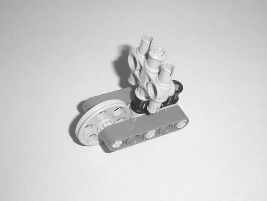 |
Figure 3-23. The rear-wheel is almost done . . . |
Figure 3-24. The final rear-wheel assembly—set this aside for now |
Finally, Figure 3-25 shows the parts needed to start the rear-wheel base.
 |
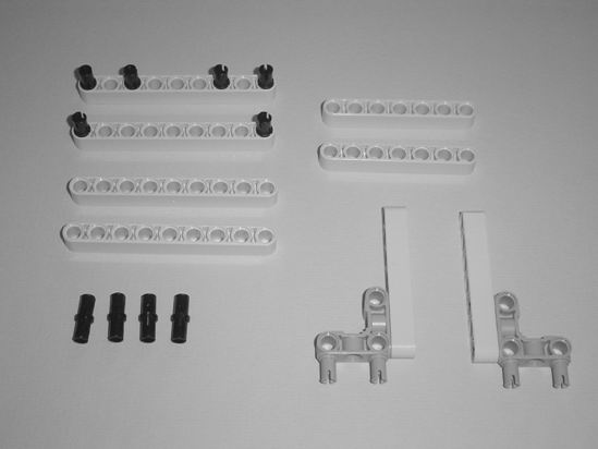 |
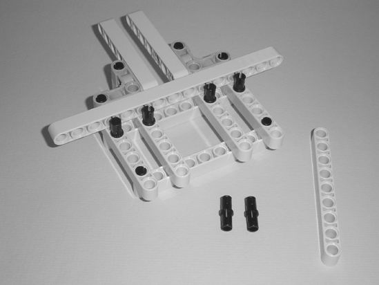
Figure 3-25. Locate these parts to start the base that will hold the rear-wheel. |
Figure 3-26. Begin by connecting the parts as shown . . . |
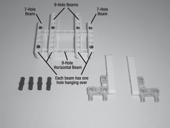
Figure 3-27. Place the 7-hole and 9-hole beams as shown . . .
Note In Figure 3-27, the two 9-hole beams and the two 7-hole beams are placed so that each beam has one hole "overhanging" the horizontal 9-hole beam (at the bottom). This is also a good place to mention that I'll occasionally use "callouts" in the figures. These "callouts" are simply text in the figure itself, sometimes with lines or arrows. Figure 3-27 uses callouts to indicate the 7-hole and 9-hole beams, and how they "overhang" the horizontal 9-hole beam.
 |
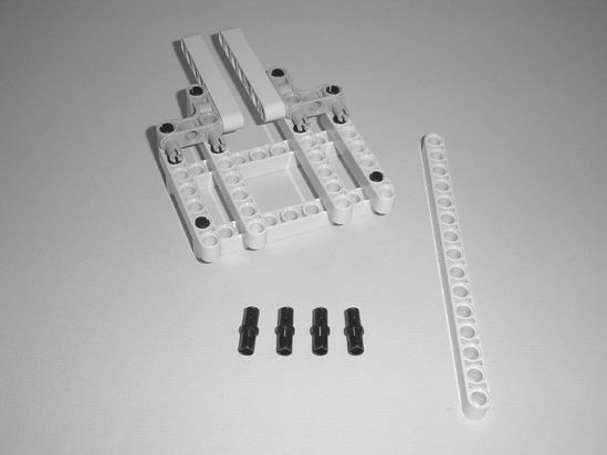 |
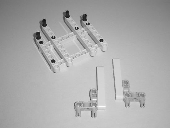
Figure 3-28. Place the four connectors in the top of the 7-hole and 9-hole beams. |
Figure 3-29. Connect the parts as shown. The four connectors and 15-hole beam are new. |
 |
 |
Figure 3-30. Connect the new parts as shown. The two connectors and 9-hole beam are new. |
Figure 3-31. Connect the new parts as shown. Locate the 9-hole beam and the two quad-connectors shown. |
Note Between Figure 3-31 and Figure 3-32, be sure to spin the rear-wheel base around. You'll see in Figure 3-32 that the base is now facing the opposite direction. Look at Figure 3-32 carefully—you'll see that the 9-hole beam has two holes overhanging at the back and that the two quad-connectors are connected facing rearward.
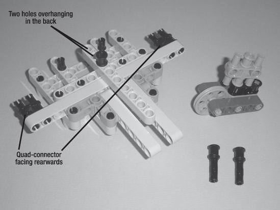
Figure 3-32. Connect the new parts as shown. Locate these two connectors and the rear-wheel.
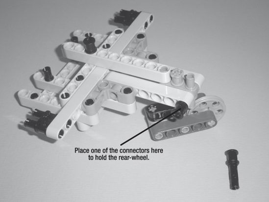
Figure 3-33a. You'll use the two connectors to connect the rear-wheel to the base. One connector is placed on the left side and the other on the right side.
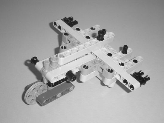
Figure 3-33b. Another view of the final rear-wheel base
Congratulations! You've finished the rear-wheel base. Do a quick check and compare the base you assembled to the one shown in Figures 3-33a and 3-33b. If you're satisfied with it, now it's time to pull all the sub-assemblies together.
You should have the following ready to go:
- Head and neck assembly
- Main body with motor/wheel combinations
- Rear-wheel base
- Cable frame
Place them all within reach. It's time to finish building the ExploroBot.
Fourth Section: Put It All Together
Take the main body assembly and the rear-wheel/base and turn them upside down. You'll see this in Figure 3-34.
Note Connecting the rear-wheel/base and the main body can be a little tricky. Before attempting it, take a good look at Figure 3-34 and Figure 3-35. I've used callouts again in Figure 3-34 to show you where the two sub-assemblies will connect. Between the two figures, you can see that the two quad-connectors will connect to the back of the motors. The two connectors on the back of the Intelligent Brick (see Figure 3-11) will go up into the 9-hole beam as indicated in Figure 3-34.
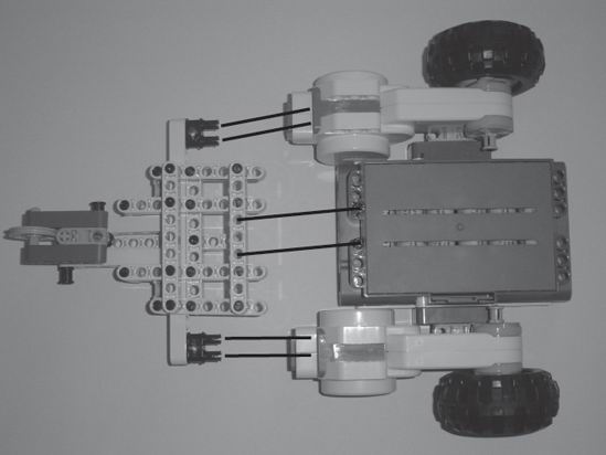
Figure 3-34. Turn the main body and the rear-wheel/base upside down to connect them.
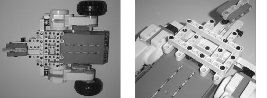
Figure 3-35. Two different views showing how the main body and the rear-wheel/base connect.
Figure 3-36 shows the assembled main body and rear-wheel/base as well as the head/neck assembly and cable frame.
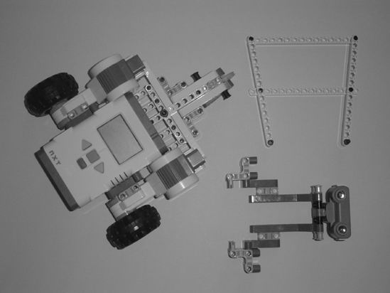
Figure 3-36. Head/neck, cable frame, and the main body and rear-wheel/base assembly
Next, connect the cable frame to the main body as shown in Figure 3-37a.
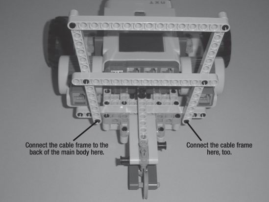
Figure 3-37a. The cable frame connects to the back of the main body.
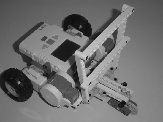
Figure 3-37b. Another view of the connected cable frame
Finally, on the front of the main body, you're going to connect the head/neck assembly as shown in Figure 3-38.
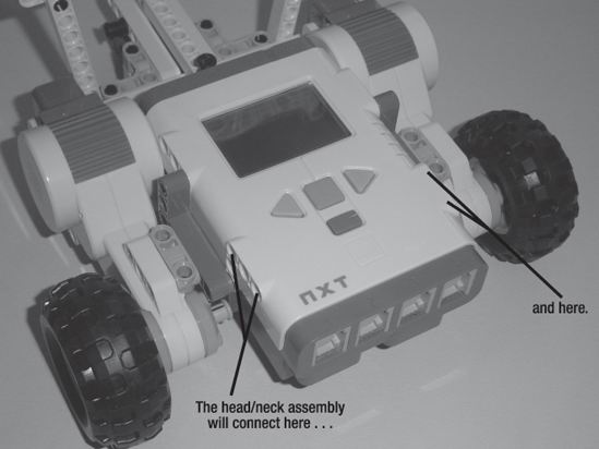
Figure 3-38. The head/neck assembly will connect to the main body here.
You'll see the head/neck assembly connected to the main body in Figure 3-39. Take a close look and you'll see exactly where the left and right neck components connect to the Intelligent Brick.
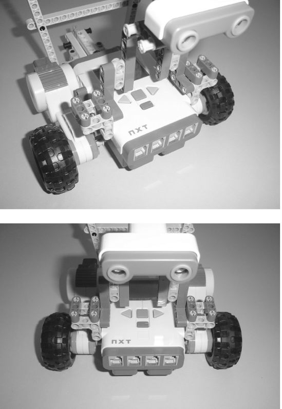
Figure 3-39. The head/neck assembly connected to the main body
Guess what? You're done with building the ExploroBot. To complete the actual bot, you need to do the following:
- Connect a cable from the Ultrasonic Sensor to Port 4 (see Figure 3-40).
- Looking at the back of the ExploroBot (see Figure 3-41), connect a cable from the left motor to Port C.
- Connect a cable from the right motor to Port B ( see Figure 3-41).
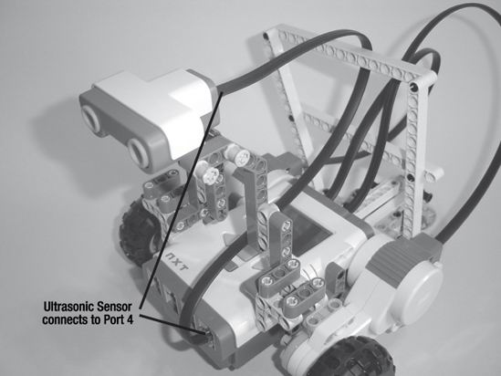
Figure 3-40. The Ultrasonic Sensor connects to Port 4.
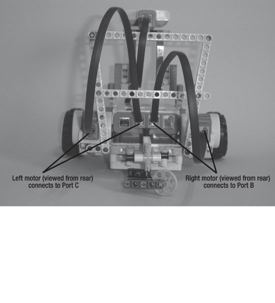
Figure 3-41. The motors are connected to Port B and Port C.
And that's it. You've built the ExploroBot.
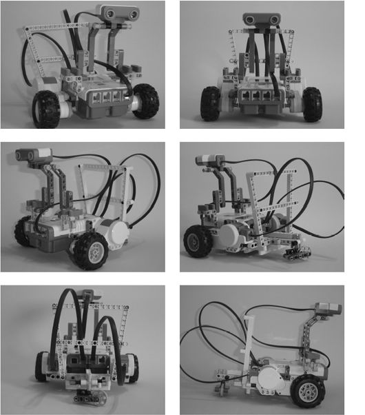
Figure 3-42. The completed ExploroBot
Chapter 4 is going to cover the programming of your ExploroBot. Without the programming to tell the bot how to behave, you've got a nice paperweight. And a locked tomb door.
So, on to the next chapter.