
CHAPTER 7
StringBot—Build It
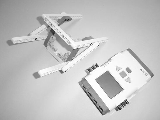
Figure 7-1 shows my version of the StringBot. It's a strange-looking device, but it does work. If you ever want to have some fun, try showing your bot design to others who are unfamiliar with it. Ask them "What do you think it does?" and be ready for some surprising answers! I showed this to a couple of people and the most surprising response was this: "How does it roll along the floor with only one wheel? The smaller wheels don't look like they'll help hold it up." Just goes to show that you cannot judge a book (or a bot, in this case) by its cover.
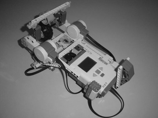
Figure 7-1. Evan's version of the StringBot
Where to Start?
Some people have no trouble just clicking pieces together. Others have more difficulty and find themselves sitting and staring at all those wonderful plastic pieces with no idea where to start. I find myself in both situations often. Some days I'm ready to go, with ideas flowing so fast I have difficulty deciding which one to build first. Other days, I pick up a few pieces, snap them together, shake my head, and take them apart. It can be frustrating.
Hopefully by now you're starting to see the importance of the Design Journal page. It can help you to at least start building something—ANYTHING—with a basic shape and concept. Just sit down with your Design Journal page and look over the sketches. Read over the Mindstorm section and see if anything sticks out as a good place to start. I always start with the Intelligent Brick. Since it's a required part for all bots, it just seems to me to always be the best place to begin.
Before we move into the actual building instructions for the StringBot, I want to mention a few things that happened during my initial construction:
- I mounted the motors on the sides of the Brick, with the Brick parallel to the floor. It worked, but I couldn't see the LCD screen when the bot moved away from me. I chose to mount the Brick hanging vertically.
- I tried to run my StringBot on the string without the rubber wheel. As predicted, at high speeds the pulley wheels would just spin and the bot wouldn't move. I had to set the motors to a very low speed for it to move. It took too long to reach the jar and come back.
- I used the small pulley wheels initially to ride the string. But no matter what happened, the StringBot kept jumping the string. So I used the wider rubber wheel rims (minus the rubber) with a couple of beams used as "string guides" to keep the bot going straight. And it works great.
One thing I would suggest is to keep a builder's notebook (along with your Design Journal pages). In this notebook, you should write down observations while you are playing—I mean building—robots. Write down things like you see in the above list. The next time you decide to build a robot that possibly rides a string, a quick review of your notebook will remind you that the small pulley wheels aren't the best method. You can also use it to draw sketches of bots, special assemblies, and other things that you might use in the future.
This is the last time I will mention it (because most people don't like to be told things twice), but as you're following along with the building instructions, if you get stuck or can't figure out the next step, just take a short break. Look ahead at the next few figures in the chapter and see if you can use the different angles to determine the proper placement of a confusing piece. Trust me, I've built these bots over and over again to test the instructions. I've done my best to give you clear views from the right angles for where parts should be placed. Count holes on beams to determine where I've placed those small connectors (for example, 5 holes from the top on the 15-hole beam) or skip ahead and look at the final bot image. If your StringBot looks similar to this one with a couple of minor differences—that's okay! You might have found a better solution anyway!
You'll figure it out, so don't let the StringBot stress you out. You're still having fun, right?
Note I would enjoy seeing your modifications to the StringBot—or maybe you've created something completely different. Take a picture and e-mail it to me. My e-mail address is in the Introduction.
Okay, let's go build the StringBot.
Step by Step
I've broken the StringBot building instructions into three sections. The first section consists of the Intelligent Brick, framework, and motors. The second section will add in the wheels-on-string system and the string guides. The third section will be the carrier arm and motor assembly that will be used to drop objects. These three sections will be connected and wired up and you'll have your StringBot.
I'll continue to add comments to the sections where I think a little help is needed. And when you see an image with text and arrows, pay special attention because there might be a tricky placement that you need to focus on.
Just like the ExploroBot instructions, I'll add new parts to an image shortly before those parts are going to be used.
First Section: Brick, Framework, and Motors
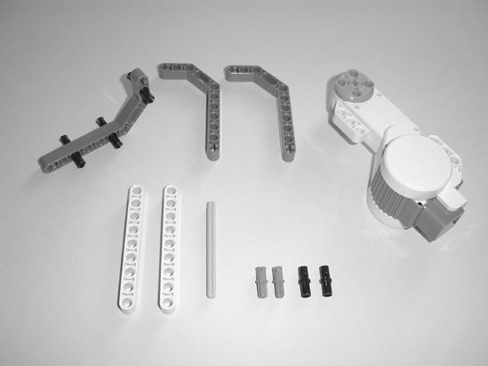
Figures 7-2 through 7-19 show you all the components used to build the initial StringBot frame with motors. Let's start off with the pieces you see in Figure 7-2.
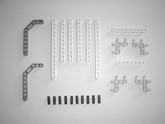 |
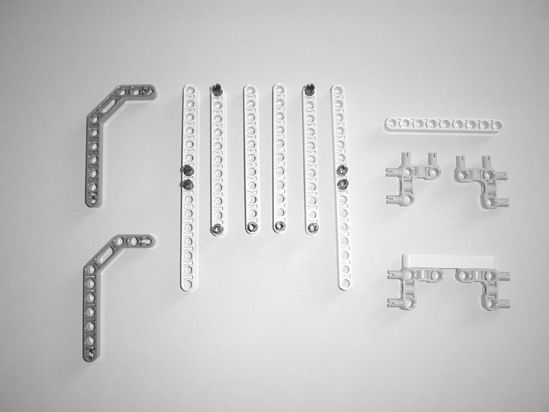 |
| Figure 7-2. Starting pieces for the StringBot | Figure 7-3. Place the ten small black connectors in the beams as shown. |
 |
 |
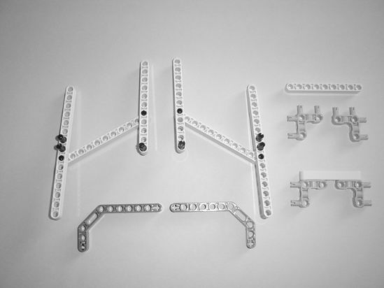
| Figure 7-4. Connect the beams like this—count the holes to help determine placement. | Figure 7-5. Place the angled dark gray beams to add strength to the frames. |
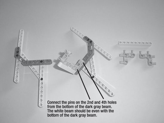
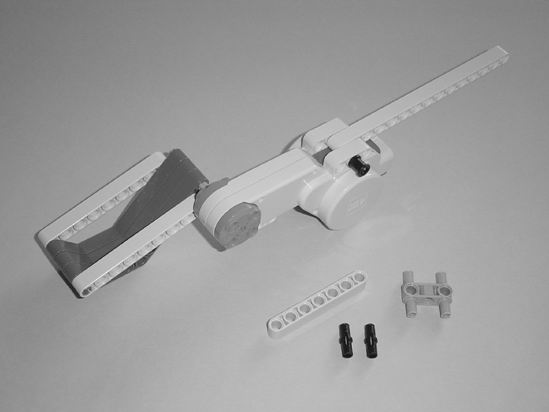
Figure 7-6. Connect the small 7-hole beam to the right-side frame as shown.
 |
 |
| Figure 7-7. Connect the left-side frame to the right-side frame. | Figure 7-8. Grab the Brick and six small black connectors (often called friction pins or friction pegs). |
Note What I call the "small black connectors" have an official Lego part number. I don't like using numbers to reference parts unless absolutely necessary—but if you must have this information, the part number is 2780.
 |
 |
| Figure 7-9. Orient the Brick as shown and get ready to attach it to the framework. | Figure 7-10. Connect the framework to the Brick. |
At this point, take a short break and compare your StringBot frame to Figure 7-10. Do they match? If not, try and correct the problem by going back through the figures to find the difference. You'll be connecting the motors in very specific locations, so it's important to have your framework match as closely as possible the one shown in Figure 7-10. Okay, let's continue . . .
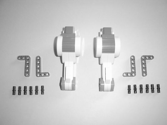 |
 |
| Figure 7-11. The motors and the components used to connect them to the framework. | Figure 7-12. Place the small black connectors in the motors as shown. |
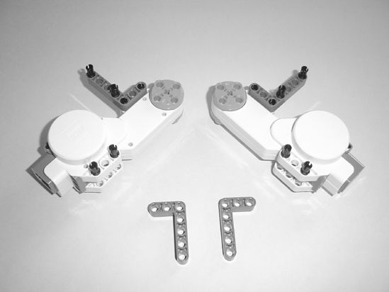
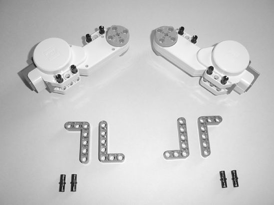
Figure 7-13. Connect an L-beam to each of the motors.
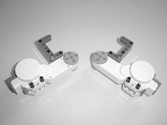
Figure 7-14. Connect the next L-beam to each of the motors.
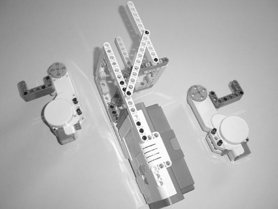
Figure 7-15. Grab the Brick/framework and orient it with the motors as shown.
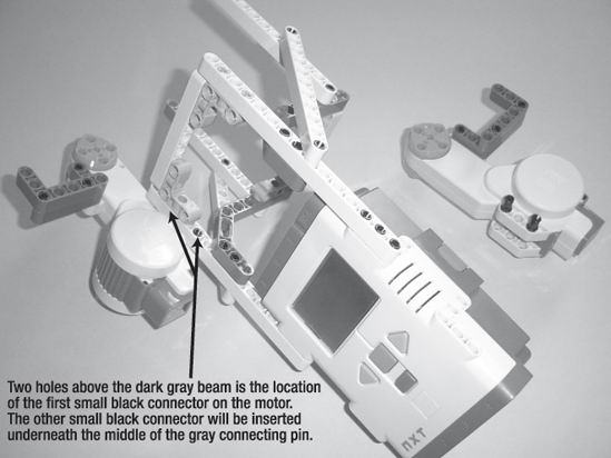
Figure 7-16. Connect the left motor as shown.
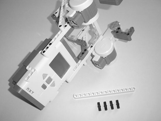
Figure 7-17. Connect the right motor as shown.
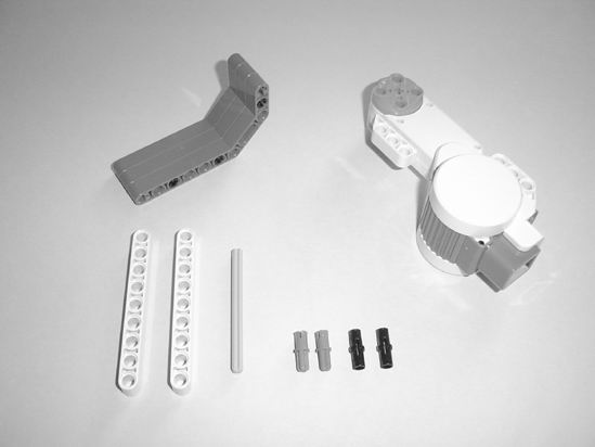
The final step for this section is to reinforce the two motors with a 15-hole beam. Figure 7-18 shows the pieces used, and Figure 7-19 shows how to connect them to the motors. (And while you're at it, go ahead and grab the other components shown in these figure because you'll need them for the second section.)
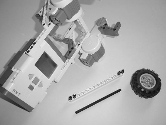
Figure 7-18. Insert the small black connectors into the 15-hole reinforcement beam.
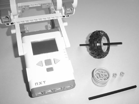
Figure 7-19. Place the 15-hole reinforcement beam as shown.
Now let's get the wheels-on-string system created . . .
Second Section: Wheels-on-String System and String Guides
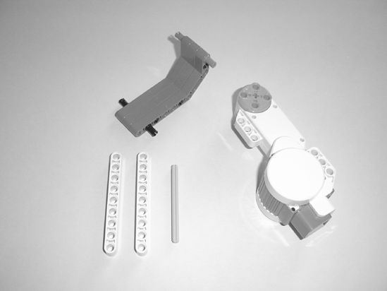
When I say "wheels-on-string system," I'm talking about the pieces needed for the StringBot to roll along the string. For this version of the StringBot, there will be two small rims used as guides (take off the rubber tires) and one rubber wheel (with rim inside) used to apply friction to the string. There will also be two 15-hole beams used as "string guides"—these will help keep the bot from jumping the string and not returning to you. We're going to start from Figure 7-19 where you'll see some of the parts used. Figure 7-20 shows the first wheel rim assembly.
Figure 7-20. Assemble your first wheel rim guide as shown.
In Figure 7-21 the Brick/framework assembly has been flipped over. You can also use this image to count holes for correct placement of the first wheel rim guide (third hole back on each side).
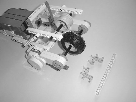
Figure 7-21. Place the rubber wheel and your first wheel rim guide as shown.
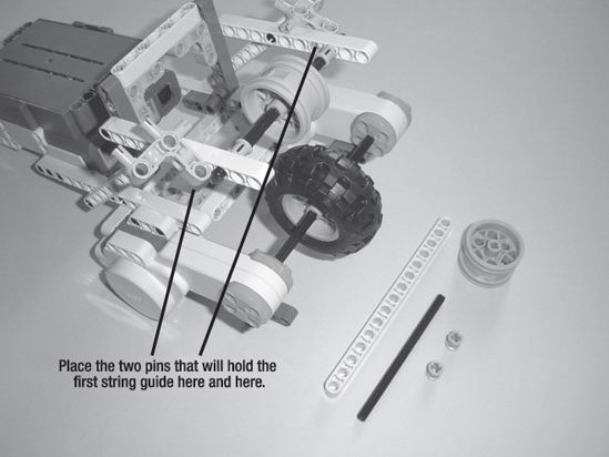
Figure 7-22. Place the pins that will hold the first string guide.
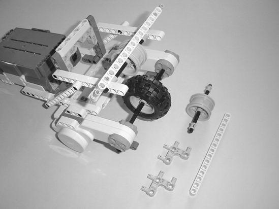
Figure 7-23. Place the 15-hole string guide beam and assemble the second wheel rim guide.
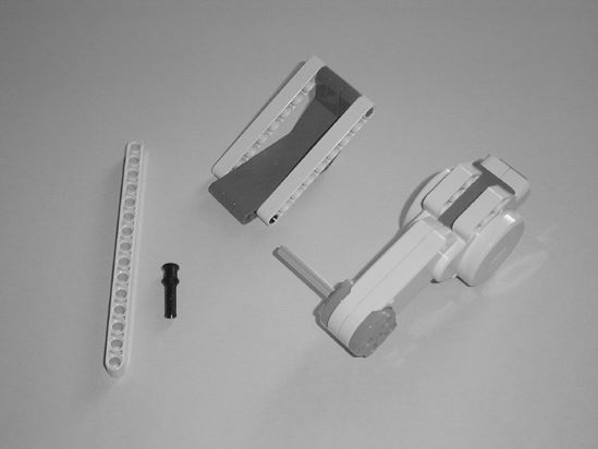
In Figure 7-24 you'll see that the Brick/framework has been flipped over. This is where you'll place the pins for the final string guide. You'll also place the final wheel rim guide.
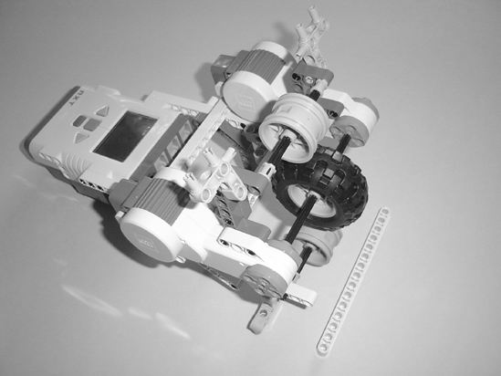
Figure 7-24. Insert the final wheel rim guide and connect the pins for the final string guide.
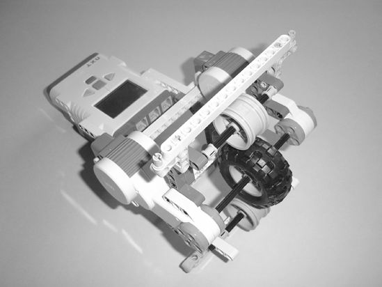
Figure 7-25. Place the final 15-hole string guide.
Figure 7-26. The sound sensor and pin are needed next.
Figure 7-27. Connect the sound sensor to the Brick.
Okay, the StringBot is almost finished. Are you beginning to see how it will work? You'll feed a string through one of the middle holes on the front string guide. The string will then go under the first rim, then the rubber wheel, and then the second rim. Thread the string through the final string guide, and your StringBot will be able to move along the string.
That covers movement on the string, but you still need to be able to drop small objects in the jar. That's accomplished with the carrier arm.
Third Section: Carrier Arm and Motor Assembly
You're almost done. We're going to build a small carrier arm for the StringBot that will be used to carry a pebble or small coin to be dropped in the jar. The third motor will be used to control the carrier, and we'll place it on the bottom of the current StringBot assembly.
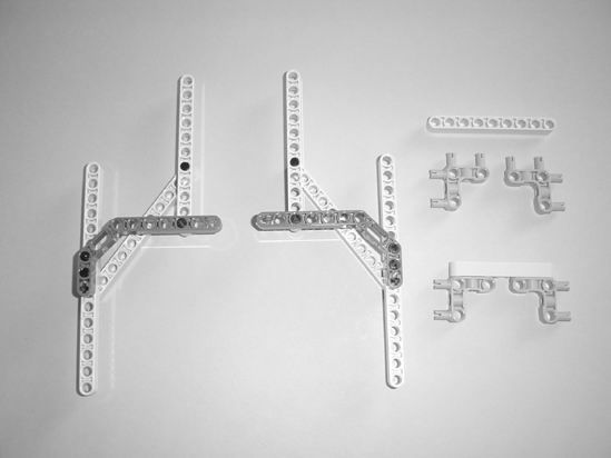
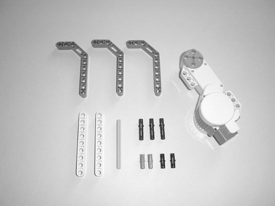
Figure 7-28 shows the majority of the pieces you'll need for this section. Go ahead and grab them and let's start building.
 |
 |
| Figure 7-28. Locate these pieces to build the carrier arm and motor assembly. | Figure 7-29. Place the small black connectors in the first dark gray beam. |
 |
 |
| Figure 7-30. Connect the other two dark gray beams to the first one. | Figure 7-31. Insert the small black connectors and blue connectors as shown. |
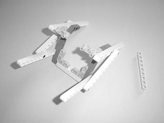
Go ahead and locate a 15-hole beam and black pin as shown in Figure 7-32. You'll use these shortly to connect the carrier arm and motor assembly to the main body of the StringBot.
 |
 |
| Figure 7-32. Insert the gray axle into the motor and connect the side beams to the carrier. | Figure 7-33. Connect the 15-hole beam to the motor as shown. |
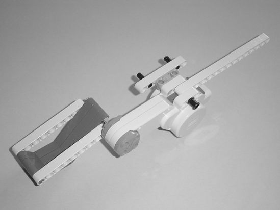
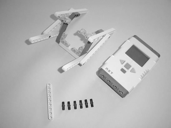
Figure 7-34. You'll use the small 7-hole beam to connect to the side of the Brick.
Now, using the main StringBot assembly (with the Brick), you're going to connect the carrier motor assembly as shown in Figure 7-35.
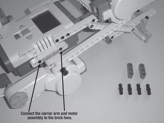
Figure 7-35. Two different views showing how the main body and the rear wheel/base connect
In Figure 7-36, notice where I've placed the four small black connectors. These will be used with two small 3-hole beams to strengthen the connection and keep the carrier arm assembly from "wobbling."
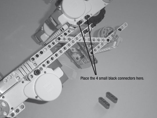
Figure 7-36. Place the four small black connectors as shown.
Next, connect the cable frame to the main body as shown in Figure 7-37.
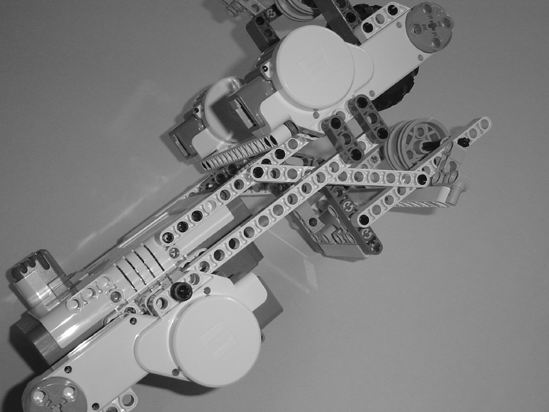
Figure 7-37. Place the 3-hole beams as shown.
And that's it! You are now the proud owner of your very own StringBot. We still have the programming to complete, but at this point if you have some string, you can place your StringBot on the string and test to see how it will roll along the string.
What I would suggest is tying one end of the string to a doorknob (on a closed door, of course). You'll feed the string through the StringBot and then tie off the other end of the string to something heavy or possibly another doorknob. Cut yourself a long piece of string so you'll have plenty of options. And my last bit of advice: tie the string so that it is as tight as you can make it with the StringBot sitting on the string. If there's too much slack in the string, the StringBot will slide towards the middle of the string. It also might not have enough power to move along the string.
Figure 7-38 shows how I've fed the string through the front string guide, under the first wheel rim, under the rubber tire, under the second wheel rim, and then finally through the rear string guide.
Figure 7-38. String up your StringBot.
Once you've got the StringBot programmed, this little fellow will move forward on the string, stop when you tell it to stop, and then move slowly towards the jar until you tell it to stop for the final time. At this point, the carrier arm will drop whatever object it is holding, pause for a few seconds, close the arm, and then return to you. Simple!
Chapter 8 will show you how to program the StringBot to do all this . . . and more. I'm going to give you some ideas on increasing the functionality of the StringBot with some additional programming. Once you've got your StringBot working, you'll fill that jar with some coins or small rocks to trigger the pressure plate—the trapped floor won't be dangerous anymore and the expedition crew will be able to cross the room and continue investigating the tomb.