
Day 9: Making the Auto-Cannon Turret Assembly
1. Switch to the Left viewport, hide everything but the bracket, and select the eight polygons shown in Figure 2-428.
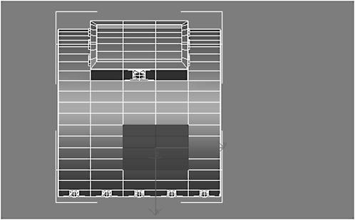
Figure 2-428
2. Detach these eight polygons as an object and then Select and Link them back to the bracket.

Figure 2-429
4. Select the eight polygons and Group Extrude them 1.0.

Figure 2-430
5. Select the four middle polygons.
Figure 2-431
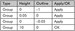

Figure 2-432

Figure 2-433
7. Unhide the nacelle and the wing_bracket so we have a frame of reference for our scale.

Figure 2-434
Figure 2-435
9. Delete the four end polygons.
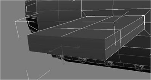
Figure 2-436
10. Select the border and then Cap it.

Figure 2-437
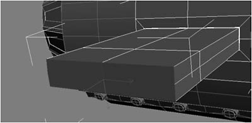
Figure 2-438
12. Select the rightmost polygon and delete it.
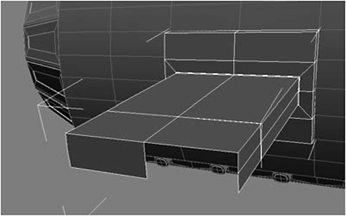
Figure 2-439
13. Select the remaining polygon and Hinge From Edge 180 degrees with 18 Segments, using the middle segment you created with the Cut tool as the hinge.
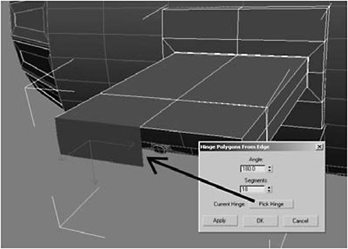
Figure 2-440
14. Switch to the Top viewport and, using AutoGrid, create a Cylinder in the middle of the rounded area you just created. Then switch to Perspective view and center the cylinder vertically.


Figure 2-441
15. Switch to Perspective view and move the cylinder down until it is roughly centered. Select Compound Objects from the Create panel and then click Boolean.

Figure 2-442

Figure 2-443
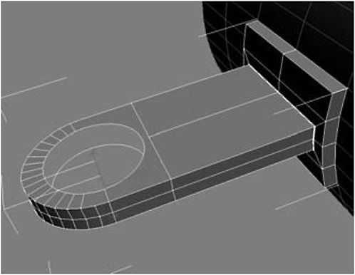
Figure 2-444
 Fire Drill: The Boolean made a really nice hole. We’d be in a wee mess if we wanted to use NURMS subdivision on this (see Figure 2-445). But we’re not going to use NURMS, so we’re fine. Nevertheless, in the interest of good modeling practice, we’ll add some cuts to mitigate the problem.

Figure 2-445
17. Make cuts where you see the dotted lines (on the top and bottom sides) in Figure 2-446.

Figure 2-446
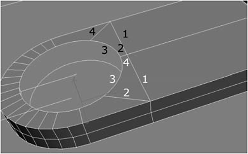
Figure 2-447
 FYI: An ideal polygon has four edges. By making six judicious cuts (three on top and three below) we’ve turned two six-edged polygons into four four-edged polygons. Now, if you do NURMS, it’s far from perfect and could benefit from some massaging, but it’s light-years better than Figure 2-445.

Figure 2-448
18. If you’ve turned on NURMS, turn it off and edge-select an edge on the inner hole and its counterpart bottom edge.

Figure 2-449
19. Click Bridge to connect the edges by creating a new polygon between them.

Figure 2-450
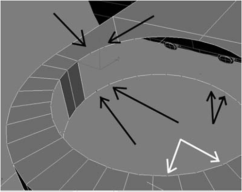
Figure 2-451
FYI: Ah, the joys of Booleans. The arrows in Figure 2-451 point to excess vertices from our cylinder having more segments than our brace. Either make matching cuts on the top and bottom so you can bridge them or remove them using the Remove tool. You can also opt to Target Weld those near other segments. Use a cut when needed to preserve the curve.
FYI: When you get to the corner, make a cut, as shown in Figure 2-452. Though the resultant polygon looks like a triangle, note that it has four edges (owing to the vertex indicated by the arrow). That is just what we want; don’t forget to do the edges on the bottom.
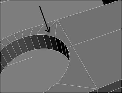
Figure 2-452
This is another pain-in-the-butt thing we have to do when using Booleans, which is why people don’t like them. Mostly this occurs when punching holes in an otherwise rectangular object. Which, unfortunately, is what we most often use Booleans for.
21. Make the same kind of cut from the middle segment to the vertex shown in Figure 2-453. This will make another four-sided polygon.

Figure 2-453

Figure 2-454
 Message: Now if we use NURMS, we get a much more acceptable result (see Figure 2-455); not great, but better. Fortunately, we’re not going to be using NURMS because we don’t want the hardware to look overly smooth and organic. We want our hunter-killer to look cold, hard, and machined. But, as you can see, if you really must have that organic look, you can get your NURMS to look as good as you want them with some more tweaking of vertices and cutting.
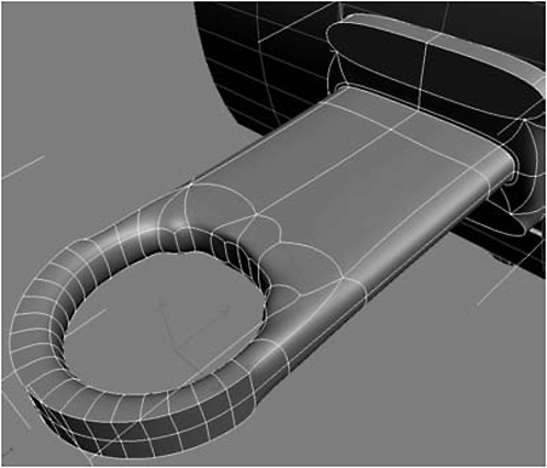
Figure 2-455
23. Edge-select the outer edges and the edges of the hole; you should have 158 edges selected.

Figure 2-456
FYI: You can either select them by hand, or you can polygon-select the entire object and Shift+Ctrl on Edge select to select the edges. If you choose the latter, you’ll have to deselect edges you don’t need. It takes about the same amount of time either way.
24. Chamfer the edges by 0.06 and then by 0.02.
25. Click the wing_brace and attach this object to it, making them a single object.
26. Do a test render.

Figure 2-457
27. Zoom in on the area that attaches to the wing_brace, go to the Create panel, select Extended Primitives, and create a Gengon in the left corner using AutoGrid.
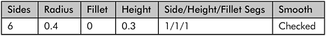

Figure 2-458
28. Make three clones, place one in each corner, and then use the Rotate tool to offset each one a little so they’re not all turned in the same direction (like they were put on by hand).
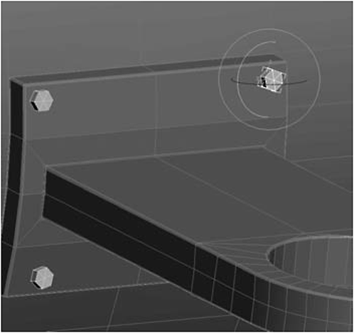
Figure 2-459
29. In the Perspective view, use the Move and Rotate tools to make sure the gengons are touching the surface of the brace (the way you did with the rivets). Hit F9 to render.
Figure 2-460

Figure 2-461
30. Switch to the Top view. Under the Create panel, pick Extended Primitives, and then create a Chamfer Cylinder in the center of the hole in the brace.


Figure 2-462
31. Switch to the Perspective view and use the Move tool to move the chamfer cylinder into place on the brace (around –27 in the local Z axis).
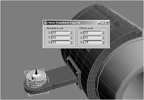
Figure 2-463
32. Use the Rotate tool to straighten the chamfer cylinder in its cradle.

Figure 2-464
33. Center and align the chamfer cylinder.
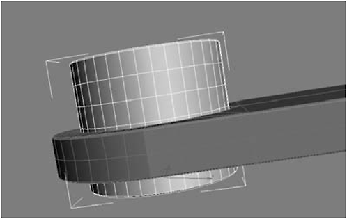
Figure 2-465
34. Rename the chamfer cylinder cannon_turret, convert it to an Editable Polygon, and Select and Link it to the brace.
35. Select and delete the 216 polygons in the center of the top and bottom of the cannon_turret.

Figure 2-466
36. Border-select the top and bottom holes you made and then Cap them.


Figure 2-467

Figure 2-468
38. Click Grow until the top of the turret and the stem are selected.
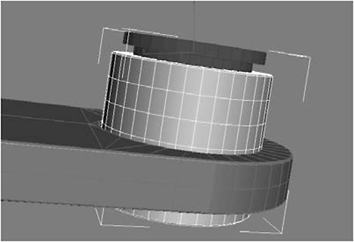
Figure 2-469
39. Click Detach and detach them as an object, naming the object cannon_mount.
40. Select and Link the cannon_turret to the wing_brace, then Select and Link the cannon_mount to the cannon_turret.
FYI: Detaching the cannon_mount from the cannon_turret allows us to rotate the mount independent of the movement of the turret. That said, it behaves as if its axle is attached to the mount, which is the reason we used Select and Link.

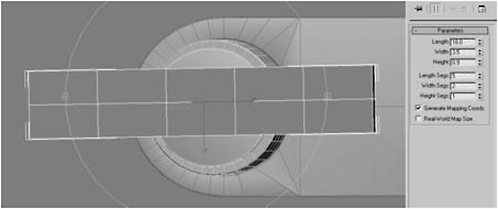
Figure 2-470
42. Convert the box to an Editable Polygon and place the box so that it is evenly positioned on the turret.
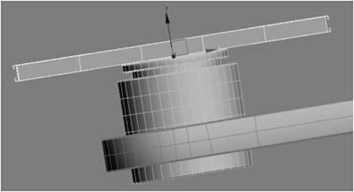
Figure 2-471
43. Select the box’s rightmost edge, as shown in Figure 2-472, click Loop, and then move it 2.0 in the X axis.

Figure 2-472

Figure 2-473
44. Repeat step 43 on the other side, but use –2.0 for the X axis value.
45. In the Top view, select the middle two polygons and click Bevel Settings:
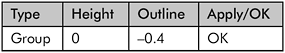
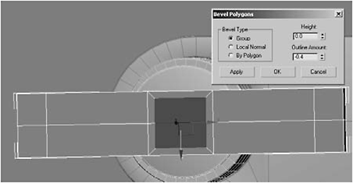
Figure 2-474
46. Scale the polygons in the Local X and Y down to 80.

Figure 2-475

Figure 2-476
48. Extrude by Local Normal 1.2.

Figure 2-477
49. In the Top view, create a Gengon over the stub you just created (start with these values):

Figure 2-478
50. Switch to Perspective view and lower the gengon onto the stub and adjust it so it is properly positioned.

Figure 2-479
51. Reduce the Radius to 1.684 and the Height to 0.921.
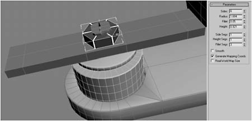
Figure 2-480
52. Convert it to an Editable Polygon, rename it nut, Select and Link the nut to the swivel, and then Select and Link the swivel to the cannon_mount.
53. Select the four polygons on the sides of the top of the swivel and scale them down to 60 in the local Y axis:

Figure 2-481
54. Group Extrude by 11, delete the two polygons farthest from you, and then select the remaining two.
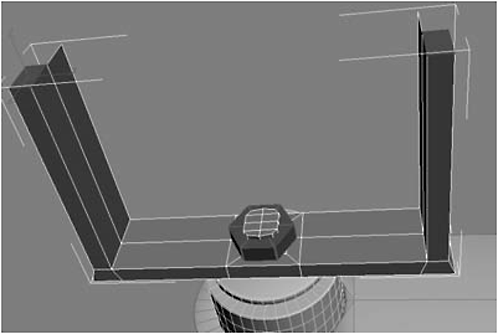
Figure 2-482
55. Hinge From Edge, 180 degrees with 18 Segments, using the far edge of the remaining polygon as the hinge. Then delete the back-facing polygons and Weld the vertices to merge.
56. Select the four center polygons on the top of the part of the swivel that pierces the bolt.
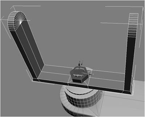
Figure 2-483
57. Click the Grow button twice, switch to wireframe, and deselect everything except the polygons shown in Figure 2-484.

Figure 2-484
58. Click Detach and detach as an object.
59. Switch to Vertex selection mode and move the vertices until the object is more rounded; it doesn’t have to be perfectly round.
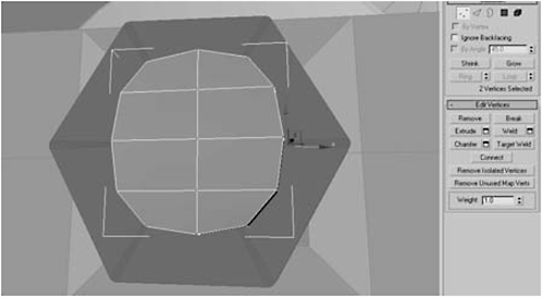
Figure 2-485
60. Add a MeshSmooth modifier to the stack and set the method to NURMS with 2 Iterations.
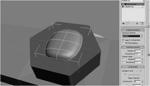
Figure 2-486
FYI: So why use a modifier instead of just clicking Use NURMS? Well you could certainly do it that way, but I want to reattach this piece to the swivel, and I want it to retain its smoothing. A MeshSmooth modifier allows me to smooth the object, then collapse the stack so the smoothing becomes a permanent part of the object.
61. Convert the object to an Editable Polygon to collapse the stack, select the swivel, click Attach, and reattach the object to the swivel.
62. The swivel should still be selected, so add a MeshSmooth modifier to its stack, set the Subdivision Method to Classic this time (to give it a boxier look), and leave the Iterations at 1 (again to give it a boxier look).

Figure 2-487
63. Convert it to an Editable Polygon to collapse the stack, then Select and Link the nut to the swivel and Select and Link the swivel to the cannon_mount. Do a quick render.

Figure 2-488
Day 10: Building the Auto-Cannon
1. Create a Box within the swivel, position it as shown, and convert it to an Editable Polygon.

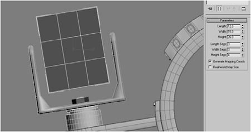
Figure 2-489
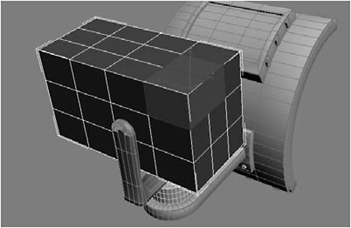
Figure 2-490
3. Select an upper edge and a middle edge from where you deleted the polygons, and click Bridge.

Figure 2-491
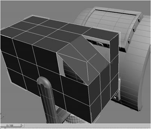
Figure 2-492
5. Cap the borders of the two triangular holes.

Figure 2-493
6. In the Front view, at the intersection of the horizontal and vertical edges on the lower-front left, use AutoGrid to create a Tube with these settings:

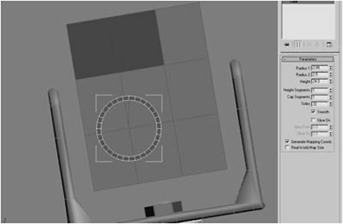
Figure 2-494
7. Convert to Editable Polygon, rename it cannon_barrel, select one of the edges touching the body, and then click Loop.
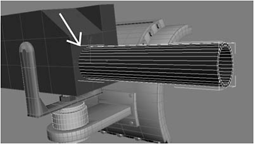
Figure 2-495
8. Click Create Shape From Selection and name it gasket.
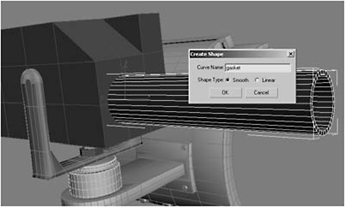
Figure 2-496
9. Hit H, select gasket, choose Enable In Viewport and Enable In Renderer, and convert it to an Editable Poly.

Figure 2-497
10. Select and Link the cannon_barrel to the gasket, then the gasket to the body, and then the body to the swivel. (To test this, rotate the swivel and the entire cannon should follow.)
11. Switch to the Front view, use AutoGrid to create a Tube over the barrel’s end (think silencer), and convert it to an Editable Polygon.

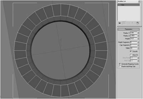
Figure 2-498
12. Rename it flash_guard and, in the Perspective view, position it on the end of the barrel.

Figure 2-499
13. Switch to wireframe and select the flash_guard’s middle 96 polygons, being sure not to select any of the interior polygons.
Figure 2-500
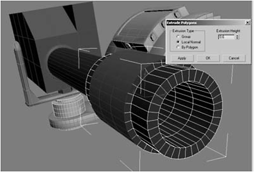
Figure 2-501

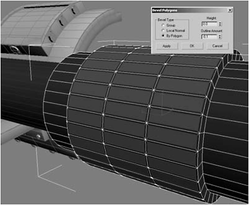
Figure 2-502

Figure 2-503
16. Delete these polygons, select the 96 polygons inside the barrel that are being intersected, and delete them too.

Figure 2-504
17. Marquee-select the middle vertices (1152), click Weld Settings, and crank up the Weld Threshold until the number of vertices drops to 960, then click OK.
FYI: Why these numbers? There are 192 polygons in the middle of the guard (96 on the outside and 96 on the inside), which means there will be 192 overlapping vertices from the deletion. When you weld the vertices together, 1152–192 = 960.

Figure 2-505
18. Select and Link the flash_guard to the barrel.
19. Where you deleted and bridged polygons on the cannon’s body, you actually created two three-sided polygons. Cut the two polygons made by the Bridge to fix this problem.
Figure 2-506

Figure 2-507
20. In the Left view, object-select the cannon’s body and move it in the X axis until two of the polygons are to the right of the swivel and one polygon is to the left.
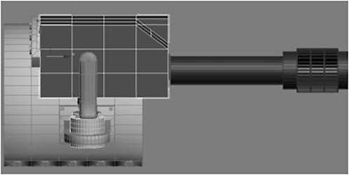
Figure 2-508
FYI: You don’t have to select anything other than the body, because you’ve linked the barrel and flash_guard to it and they will follow (this serves as the basis for rigging and animating).
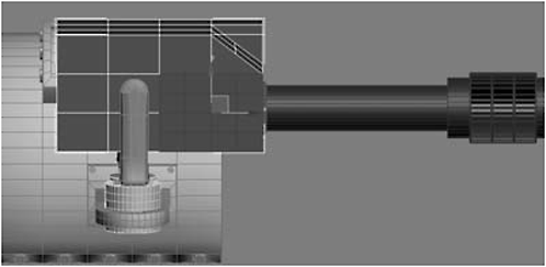
Figure 2-509
22. Select the six polygons in the middle of those you created with Tessellate.

Figure 2-510
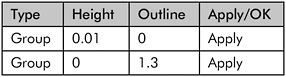

Figure 2-511
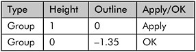

Figure 2-512
24. Extrude –1, hit Apply, and then Extrude –10. Click OK.
25. Add our Clay material to everything and do a quick render.
Figure 2-513
26. Select a segment on the inside edge of the muzzle, click Loop, click Create Shape From Selection, set the Shape Type to Linear, and name it grenade.
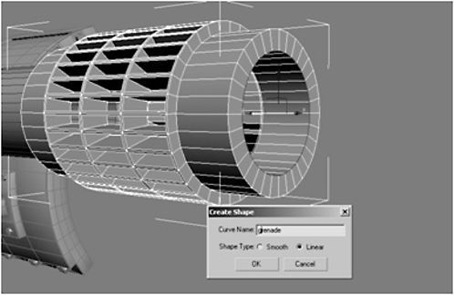
Figure 2-514
27. Hit H and select grenade, then move it out in front of the muzzle. Convert grenade to an Editable Polygon, border-select it, and Cap the back side.

Figure 2-515
28. Polygon-select the poly facing away from the muzzle, Extrude it by 0.5, and rename it shell_casing.

Figure 2-516


Figure 2-517
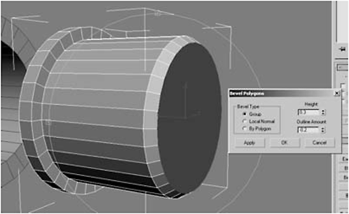
Figure 2-518

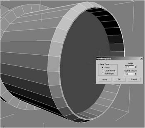
Figure 2-519


Figure 2-520
30. Delete the polygon and switch to the Front view. Create a Sphere, using AutoGrid, in the middle of the cylinder.

Figure 2-521
31. Convert the sphere to an Editable Polygon, delete the back-facing polygons, attach the sphere to the shell_casing, and then Weld the vertices together.
32. Scale the vertices in all three axes to 104, or until they make a smooth contour.

Figure 2-522
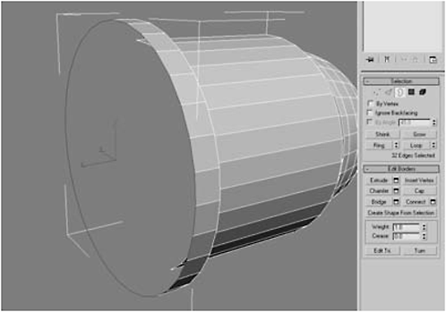
Figure 2-523
34. Click an edge on the top and bottom and click Loop.

Figure 2-524
35. Chamfer 0.04, click Apply, and then Chamfer again 0.015.
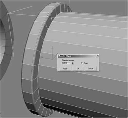
Figure 2-525
36. Add a Smooth modifier to the stack, click Auto Smooth, then convert it to an Editable Polygon to collapse the stack.

Figure 2-526
37. Object-select the grenade, click the Hierarchy tab, center the pivot to the object, and move the grenade into the ejector.
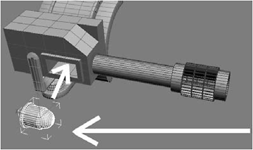
Figure 2-527
38. Scale the grenade to fit into the ejector port. (I scaled mine down to 87 in all three axes.)

Figure 2-528
39. Scale the grenade to 165 in the Y axis and then move it in the Y axis until it is in position.
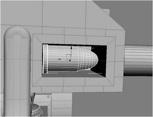
Figure 2-529
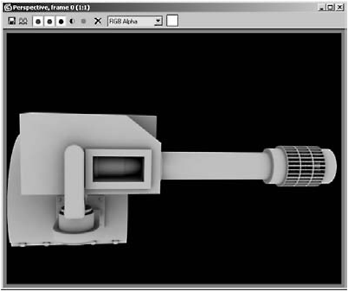
Figure 2-530
41. Select the 12 polygons in the center of the body, beneath the swivel.

Figure 2-531

Figure 2-532
Figure 2-533
43. Select and Link the shell to the body, and then move the body forward a little bit until the slice you made is to the right of the swivel and the swivel is centered over the polygon.

Figure 2-534
Message: Linking the shells is only necessary because we’re making a static model. If we were doing an animation, I would separate the grenade from the casing and create a dual particle system (one to eject the casing and the other to propel the grenade from the barrel). I would also use a gravity space warp to hold them in place.
44. Select the polygon beneath the swivel on each side, and detach them as objects.
Figure 2-535
45. Hide everything except the detached polygons and then delete the polygon shown in Figure 2-536.

Figure 2-536
 Don’t Forget: The polygon is there; you just can’t see it because you’re looking at its back side and the normal is facing away from you.
46. Select the remaining polygon and Extrude it by 0.6.

Figure 2-537
47. Arc Rotate until you are looking straight at the polygon, and use AutoGrid to create a Cylinder in the center of the polygon.


Figure 2-538
48. Unhide the swivel and Arc Rotate until you can see if the cylinder intersects with the swivel. Adjust the cylinder’s parameters until it is just touching the inside surface of the swivel and then convert it to an Editable Polygon.
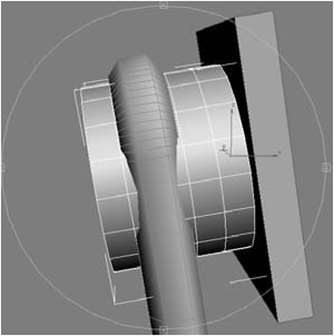
Figure 2-539
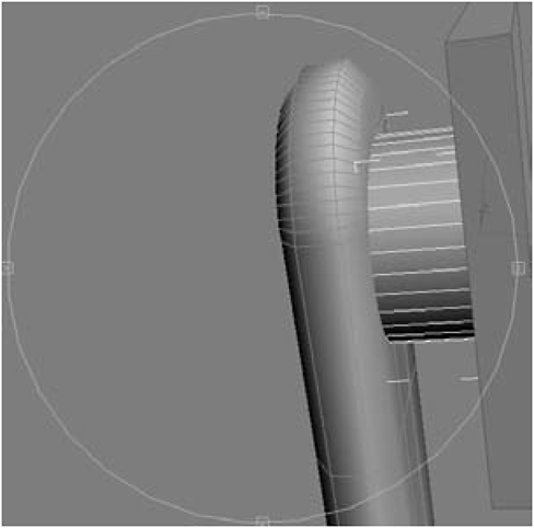
Figure 2-540
49. Create a Boolean object with the cylinder as Operand A, click Pick Operand B, click the polygon you extruded, and choose Union as the Operation.

Figure 2-541
50. Unhide all the parts to the cannon, the mounts, the wing brace, etc., then switch to the Front view and select the Boolean you made.
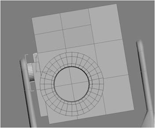
Figure 2-542
51. Switch your Reference Coordinate System to Local, Shift-drag the Boolean in the local Z axis to make a copy, and move it into position on the other side of the cannon.

Figure 2-543
52. Rotate the copy 180 degrees, move it into position, select the cannon, click Attach List, and attach the Boolean and its copy (Cylinder01 and Cylinder02) to the cannon.
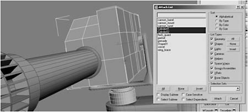
Figure 2-544
53. Select the polygon in the upper-right front corner of the cannon.

Figure 2-545
54. Click Bevel Settings:
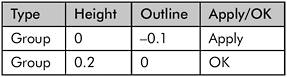

Figure 2-546
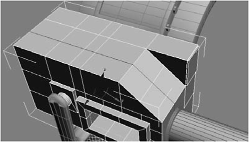
Figure 2-547
56. Select the polygons shown in Figure 2-548.

Figure 2-548


Figure 2-549

Figure 2-550

Figure 2-551
58. Select the right and left sides (inside and out) of the clip, but not the front and back.

Figure 2-552


Figure 2-553
60. Select the four outside polygons, delete them, then select the matching four inside polygons and delete them.

Figure 2-554
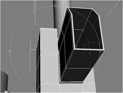
Figure 2-555
61. Use Border selection mode to select the inside and outside borders created by the deletion, and then click Bridge.

Figure 2-556
62. Repeat steps 60-61 for the polygons on the right side.
63. Clone the grenade and fill the clip; then Select and Link all the grenades to the cannon.
64. Unhide the wing, mounts, nacelle, rotors, etc., and do a quick render to see how everything fits together.

Figure 2-557
FYI: Chances are you’ll have to cheat a little by scaling either the size of the clip or the size of the grenade shell. But since we’re building a static model rather than an animation, no one should be able to tell. I had to scale my cannon down by about 10% to keep the clip from hitting the wing when I rotated it. If you do scale your cannon, be sure to scale all the cannon components, the turret, the brace, and the cannon mount.
Day 11: Detailing the Auto-Cannon
1. Use AutoGrid to create a Tube on the polygon in the upper-right front.


Figure 2-558
2. Use AutoGrid to create a Geosphere inside the tube.
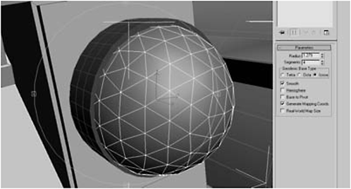
Figure 2-559
3. Convert the geosphere to an Editable Polygon, then select the half of the geosphere that will not be seen and delete it.

Figure 2-560


Figure 2-561

Figure 2-562
5. Select and Link the geosphere and the tube to the cannon, and then add the Clay material to both.
6. Convert the tube to an Editable Polygon and select the four polygons shown in Figure 2-563.

Figure 2-563
7. Group Extrude the four polygons 0.2.

Figure 2-564

Figure 2-565
9. Rotate the polygons –9.4 in the Y axis, or until they’re straight.

Figure 2-566


Figure 2-567
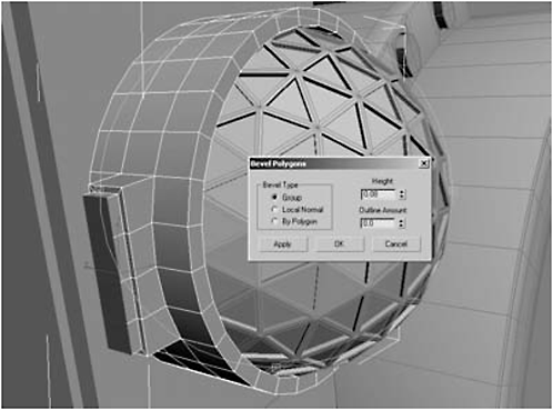
Figure 2-568
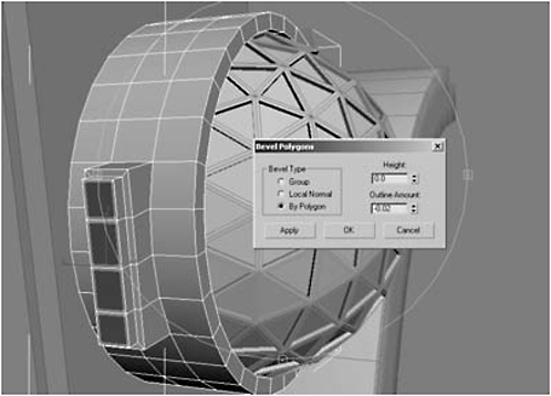
Figure 2-569
11. Select the middle two polygons and scale them down to 80 in the Z axis.

Figure 2-570
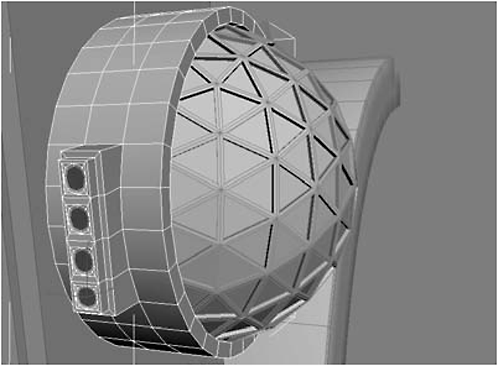
Figure 2-571
13. Use AutoGrid to create a Box on the surface above the barrel.


Figure 2-572
14. Select the polygons on the top of the box.
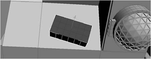
Figure 2-573
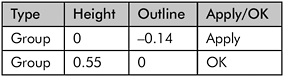
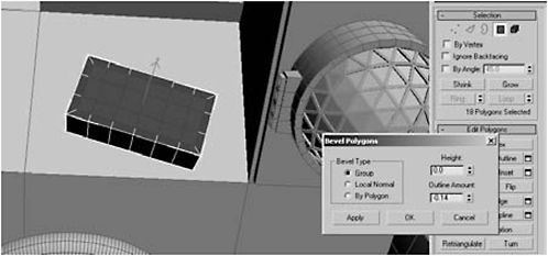
Figure 2-574

Figure 2-575
16. Click Shrink.

Figure 2-576
17. Extrude By Polygon 0.2.

Figure 2-577
18. Click Bevel Settings:

Figure 2-578

Figure 2-579
20. Click the MSmooth button and delete the polygons.
Figure 2-580
21. Scale the connector 50% in all three axes.

Figure 2-581
22. Create a linear spline connecting the far right hole on the surface plug with the bottom hole on the sensor you made using the geosphere; be sure to convert the vertices to Smooth and set the spline to be viewable in the viewport and the renderer.

Figure 2-582
23. Move the vertices until the wire is properly aligned with both plugs.

Figure 2-583
24. Clone the wire three times and move the vertices until all the wires are aligned with the plugs.

Figure 2-584
25. Select and Link all of the wires and the plug to the cannon.
26. Select the seven polygons on the left side of the cannon.

Figure 2-585
27. Click Bevel Settings:


Figure 2-586
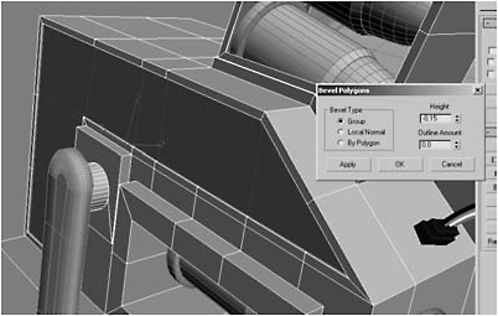
Figure 2-587

Figure 2-588
29. Convert the sphere to an Editable Polygon, delete the back-facing polys, and move the sphere so it touches the inner surface of the bevel.

Figure 2-589
30. Select the inside edges of the bevel you made on the cannon’s left side.

Figure 2-590
31. Click Create Shape From Selection and set Shape Type to Linear.
32. Select the shape, center its pivot, scale it until it runs through the middle of the sphere you just created, and move its vertices until it looks like this:
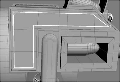
Figure 2-591
33. Select the sphere, press Shift+I to activate the Spacing tool, click Pick Path, select the spline you created in step 31, and enter 11 for Count.

Figure 2-592
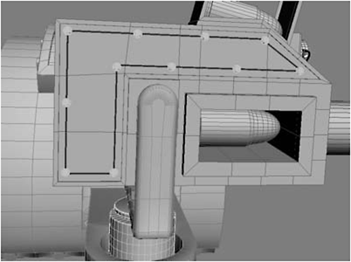
Figure 2-593
35. Make sure all the spheres connect with the cannon, select the cannon, and Attach the spheres. Do a test render.
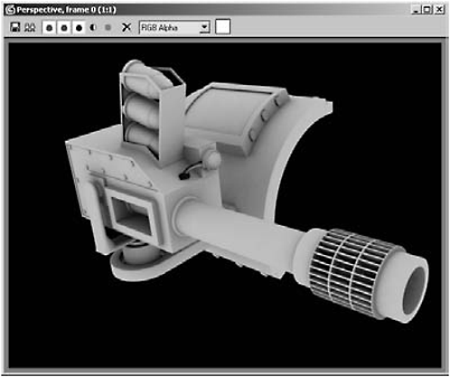
Figure 2-594
36. Select the two polygons on the front of the cannon.

Figure 2-595


Figure 2-596


Figure 2-597


Figure 2-598
39. Select the four bottom polygons on the lower-left corner of the cannon’s right side.
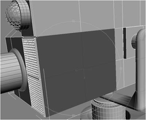
Figure 2-599

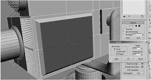
Figure 2-600
41. Control-click on the Edge selection mode icon, deselect the four edges in the middle so that only the outer edges are selected, and then Chamfer them by 0.1 and then 0.05.

Figure 2-601
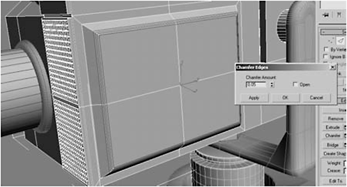
Figure 2-602
 Urgent: When we rescaled the cannon at the end of the Day 10 section, I made a mistake. I shouldn’t have scaled the turret. Now, as you can see from Figure 2-603, it doesn’t fit in the brace. The hole is too big! Since we chose to Select and Link everything, if we scale the turret, then everything linked to it will scale too!

Figure 2-603
42. Click the Schematic View button on the main toolbar.
FYI: The schematic view provides a hierarchical display of all the linkages you’ve made.

Figure 2-604
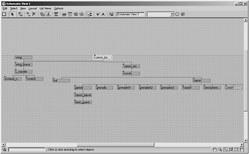
Figure 2-605
The currently selected object is displayed in white, in this case the cannon_turret. Linkages you’ve made are displayed by the green lines. The blue boxes are unselected items. As we can see from the schematic, the cannon_turret connects the entire cannon apparatus to the wing. What we need to do is to temporarily disconnect the cannon_turret, resize it, and then reconnect it.

Figure 2-606

Figure 2-607
FYI: Now if we click Unlink Selection again, nothing happens. Why? Unlink breaks the link between the object and its parent. Right now cannon_turret is the parent. So to get cannon_turret by itself, we’re going to have to select cannon_mount and then click Unlink Selection.
44. Select cannon_mount and click Unlink Selection.

Figure 2-608
45. As you can see, cannon_turret is now by itself, while cannon_mount is now the parent to all the objects comprising the cannon. Close the schematic view.
46. Select the cannon_turret and scale it (around 125) in the X and Y axes until it fills the hole in the wing_brace.

Figure 2-609
47. Border-select the hole in the middle of the cannon_turret and scale it in the X and Y axes until it closes around the cannon_mount.
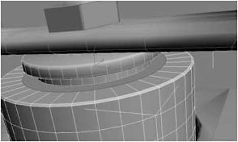
Figure 2-610

Figure 2-611
48. Click Schematic View to reopen the schematic view, click cannon_mount to select it, click the Connect button, and then drag a line from the cannon_mount to the cannon_turret to reparent them.
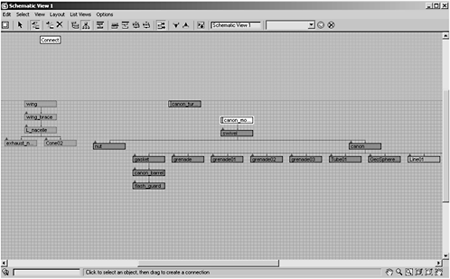
Figure 2-612
49. Click cannon_turret to select it, and drag a line to wing_brace to reparent it.

Figure 2-613
50. Close the Schematic View window.
51. Select all the sharp edges on the cannon and Chamfer them first 0.06 and then 0.02.
52. Select the three polygons on the outside surface of the swivel, on both sides.
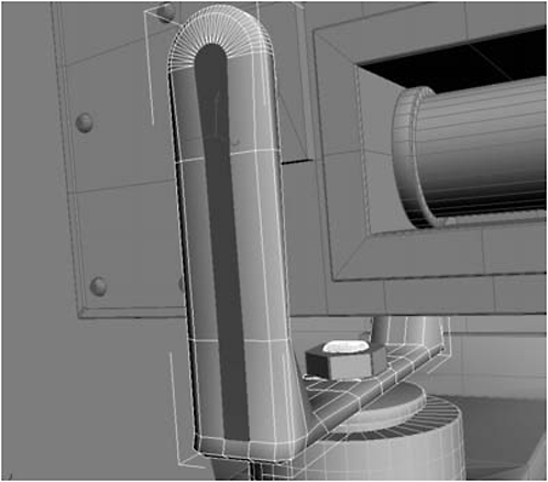
Figure 2-614
53. Group Extrude –0.2.
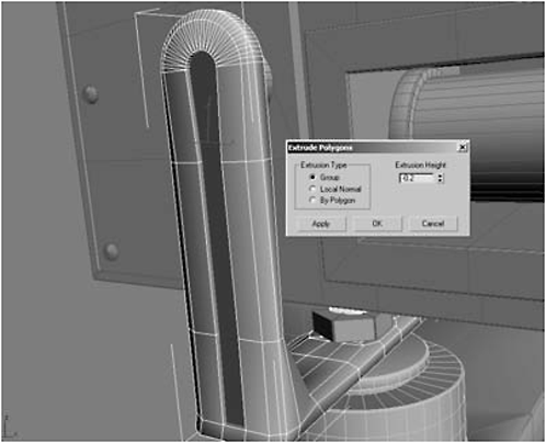
Figure 2-615
Day 12: Making the Missile Pods
1. Switch to the Front view and unhide the wing.
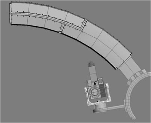
Figure 2-616


Figure 2-617
3. Switch to the Top view and center the missile beneath the wing (–45.407 in the Y axis).

Figure 2-618
4. Hide everything except the cylinder and convert it to an Editable Polygon.
5. Select and Loop the first and third segments.
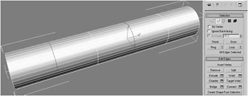
Figure 2-619

Figure 2-620
7. In the Top view, select the center two polygons at the top of the cylinder.
Figure 2-621
8. Switch to the Perspective view and select the center two polygons on top of the cylinder, then skip six polygons, select the next two, and so on, until you have a total of eight polygons selected (two polys at the 3, 6, and 9 o’clock positions, plus the polys selected in step 7).

Figure 2-622

Figure 2-623

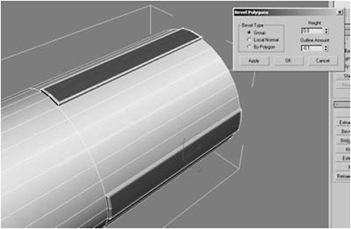
Figure 2-624

Figure 2-625
11. Select an edge one row in from the outer edge and Loop it.

Figure 2-626
12. Scale the selected edges 120 in the X and Z axes.
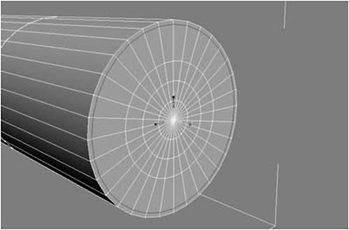
Figure 2-627
13. Select the 128 polygons in the middle of the front of the missile and extrude them by 0.01, and then delete them.
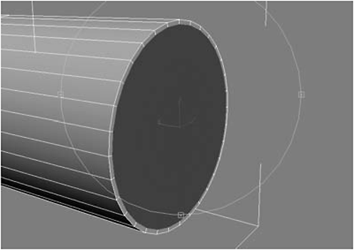
Figure 2-628
14. Switch to the Front view and use AutoGrid to create a Sphere in the center of the missile:

Figure 2-629
15. Move the sphere to the front of the missile (around –80 in the X axis).

Figure 2-630
16. Convert the sphere to an Editable Polygon and delete the back-facing polygons.
17. Switch to Vertex selection mode and select the vertex at the center of the sphere (vertex 1).

Figure 2-631
18. Turn on Use Soft Selection, click Shaded Face Toggle, and enter 4.75 for the Falloff.
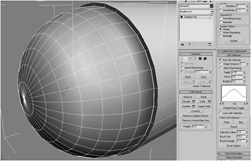
Figure 2-632
19. Move the vertex –2.2 in the Offset World Y axis to make a cone.

Figure 2-633
20. Uncheck Use Soft Selection, add a Smooth modifier to the stack, check Auto Smooth, and convert the sphere to an Editable Polygon to collapse the stack.
21. Select the cylinder, attach the sphere, select the vertices along the seam, and Weld the vertices together to merge them. (Use a threshold of 0.01; the vertices should drop from 874 to 842.)

Figure 2-634
22. Switch to the Perspective view, Arc Rotate around the rear of the missile, and select the 128 polygons in the middle.

Figure 2-635
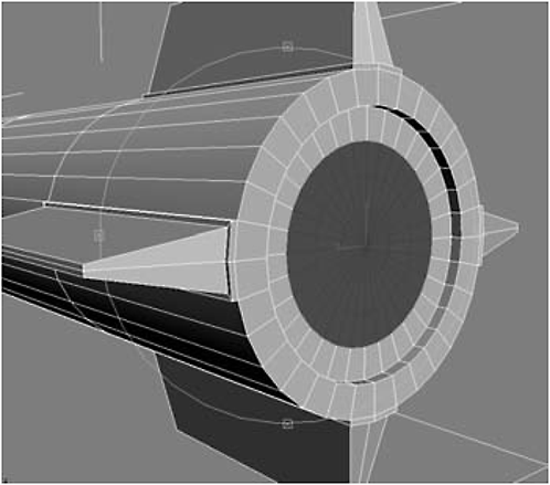
Figure 2-636
24. Move the polygons –0.20 in the Y axis.

Figure 2-637
25. Click Shrink and move the polygons –0.15 in the Y axis.

Figure 2-638

Figure 2-639
27. Click Bevel Settings:

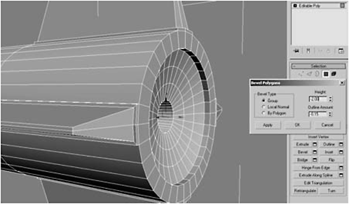
Figure 2-640
28. Add a Smooth modifier to the stack, check Auto Smooth, and convert to Editable Polygon. Switch to the Perspective view, Arc Rotate to get a good angle, and do a test render.
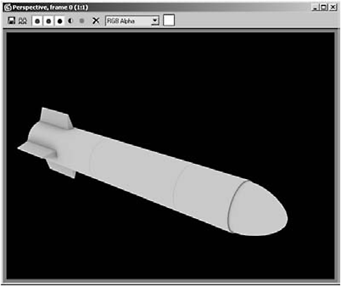
Figure 2-641
29. Switch to the Front view, and using AutoGrid, create a Tube centered around the missile:


Figure 2-642
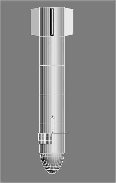
Figure 2-643
31. Convert the tube to an Editable Polygon, rename it brace, click a segment on the leftmost side, and click Loop.

Figure 2-644
32. Move the segments –0.30 in the X axis, then loop-select the segments to the right and move them 0.30 in the X axis.
33. Select the eight polygons shown in Figure 2-645.
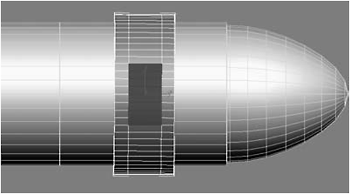
Figure 2-645
34. Extrude the polygons 0.5.
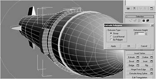
Figure 2-646

Figure 2-647
36. Group Extrude them 0.5.

Figure 2-648
37. Arc Rotate around the back and select the eight polygons shown in Figure 2-649.
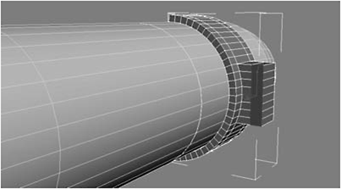
Figure 2-649
38. Zoom out, Extrude those eight polygons around 9.73 or until they reach the missile’s center, and then delete them.

Figure 2-650
39. Object-select the brace you’ve been building and Mirror it, offsetting the clone (~–18.28) until it is just forward of the fins but still intersecting the original.
Figure 2-651
40. Select the original brace, attach the clone, select the intersecting vertices in the middle, and Weld them.
41. Select both the missile and the brace, switch to the Front view, and Shift-drag down (~11.207) in the Y axis to clone a missile and brace below the original.

Figure 2-652
Figure 2-653
43. Attach the braces together and select the eight center, inward-facing polygons on all four braces as shown in Figure 2-654.

Figure 2-654

Figure 2-655
45. Delete the inward-facing polygons, switch to Vertex selection mode, select the middle vertices, and Weld the seams.

Figure 2-656
46. Select the eight inner surface polygons (top and bottom).
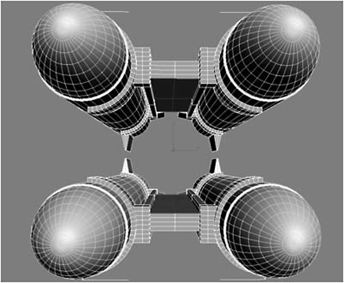
Figure 2-657
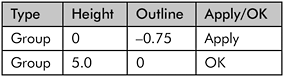
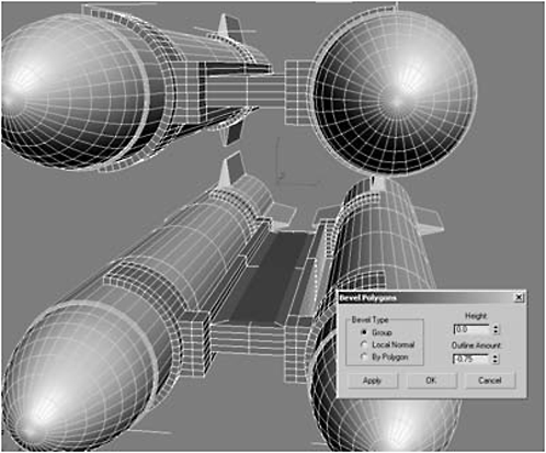
Figure 2-658
Figure 2-659
48. Delete the inward-facing polygons, switch to Vertex selection mode, select the seam vertices, and Weld. Do a test render.
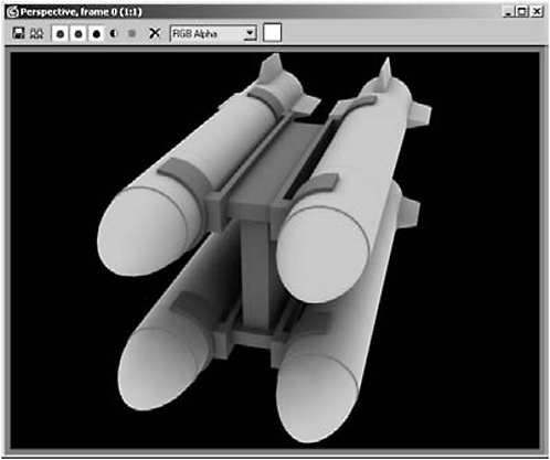
Figure 2-660
49. Select the top four polygons on the brace and Group Extrude them 3.0.

Figure 2-661
50. Unhide the wing and cannon so we can position the missiles.

Figure 2-662


Figure 2-663


Figure 2-664
52. Select and Link the missiles to the brace.
53. Center the pivot of the brace and then move the brace and position it beneath the wing. (I rotated mine around 15.29 degrees in the Y axis.)

Figure 2-665
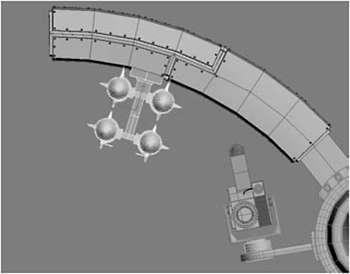
Figure 2-666
54. Add the Clay material to the brace and missiles and do a test render.
Day 13: Building the Body
1. Hide everything except the wing and switch to the Top view.
2. From the Extended Primitives, using AutoGrid, create a Chamfer Cylinder:


Figure 2-667
3. Switch to the Front view and move the chamfer cylinder to align it with the wing.
Figure 2-668
4. Increase the height of the chamfer cylinder to 26.364, increase the height segments to 3, and convert it to an Editable Polygon.
Figure 2-669
5. Select a horizontal segment, click Loop, and move the segments up to the lip of the wing (3.032 in the Y axis).
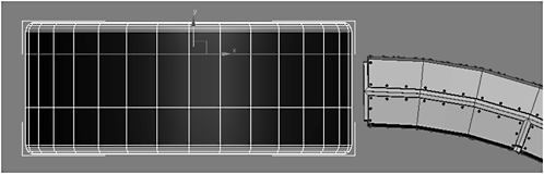
Figure 2-670
6. Select a horizontal segment, click Loop, and move the segments down to the lip of the wing (–3.493 in the Y axis).

Figure 2-671
7. Switch to the Top viewport, select the cylinder half opposite the wing, and delete it.

Figure 2-672
8. Add a Symmetry modifier to the stack.

Figure 2-673
FYI: The Symmetry modifier works like mirroring, except that any modifications that are made to the mesh after the application of the modifier will be reflected in the mirrored half as well. This means that when modeling a symmetrical object like a human face, you only need to do half the work!
9. Click the plus sign to the left of Editable Poly, as indicated by the arrow in Figure 2-673, switch to Polygon selection mode, and select the six polygons on the side of the cylinder shown highlighted in Figure 2-674.

Figure 2-674
10. Group Extrude the polygons 3.36.

Figure 2-675
11. Hide the wing, select the middle polygons between the extrusions, and delete them.

Figure 2-676
12. Select the vertices and scale them in the Y axis until the edges overlap, and then Weld the vertices.

Figure 2-677
13. Unhide the wing, select the polygons, and scale them down to 0 in the X axis.

Figure 2-678

Figure 2-679
14. Zoom in tight in the Perspective viewport and click Bevel Settings:
Figure 2-680
Figure 2-681
15. Delete the inside polygons.
16. Select the vertices surrounding the connection you made and move them until the connection is flush against the wing.

Figure 2-682
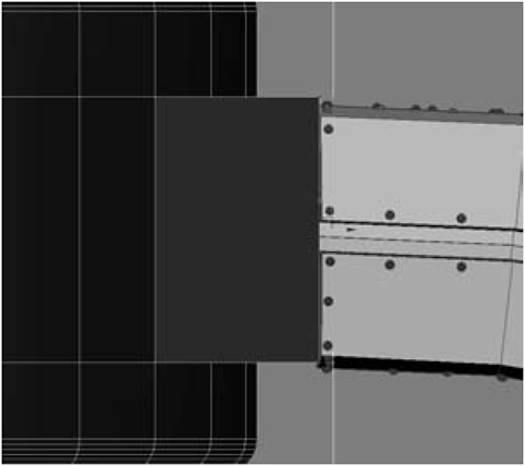
Figure 2-683
17. Move and scale the vertices until the connection is snug against the wing.
Figure 2-684

Figure 2-685
19. Add a Smooth modifier to the top of the chamfer cylinder’s stack, check Auto Smooth, and rename the cylinder bot_body. Convert it to an Editable Polygon to collapse the stack, and add the Clay material to it.

Figure 2-686
20. Select all the vertices, set the Weld setting to 0.01, and weld all the vertices.
Fire Drill: Although collapsing the stack is supposed to weld the seams if you have it checked under the Symmetry modifier, it’s been my experience that the welding is as reliable as Loop — sometimes it works and sometimes it doesn’t. To be on the safe side, a weld threshold of 0.01 should only weld together vertices that are actually overlapping and should be welded.
FYI: Should there be some polygons inside of the chamfer cylinder visible through the wing connection, you’ll want to delete those too. Sometimes (not often), welding symmetrical objects can leave artifacts inside an object.

Figure 2-687


Figure 2-688


Figure 2-689
23. Switch to the Top viewport and, using AutoGrid, create a Box on the top of the body:

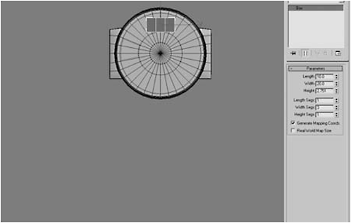
Figure 2-690
24. Convert the box to an Editable Polygon, rename it boom_mount, and select the right and left polygons.
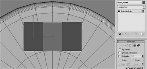
Figure 2-691
25. Click Bevel Settings:

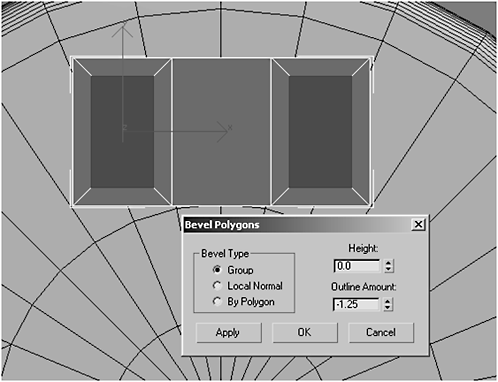
Figure 2-692
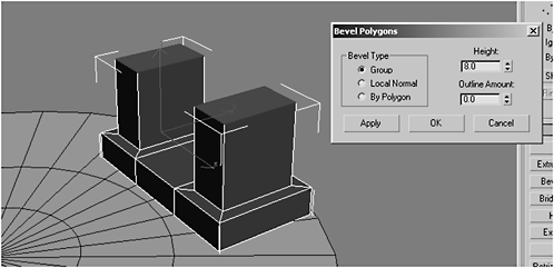
Figure 2-693
26. Select the four edges indicated in Figure 2-694 and then click Connect. (Connect creates a new segment that connects the two you selected, which in this case forms an H.)

Figure 2-694

Figure 2-695
27. Select the bottom two polygons and delete them.

Figure 2-696
28. Select the top-right polygon and Hinge From Edge 180 degrees with 18 Segments using the edge where you deleted the polygons as the hinge. Delete the back-facing polygon and Weld the vertices. Repeat for the other side.

Figure 2-697
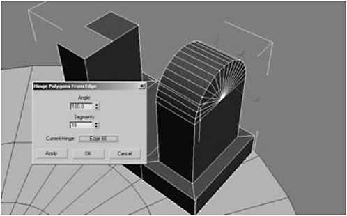
Figure 2-698
29. Switch to wireframe and select the sharp edges (84 total) and Chamfer them by 0.1 and then 0.04.
Figure 2-699

Figure 2-700
30. Add a Smooth modifier to the stack, click Auto Smooth, convert to an Editable Polygon, and then Select and Link to the body.
31. Switch to the Top viewport, select the boom_mount, and center the pivot.
32. Hold down the Shift key and drag down in the Y axis to make a clone and position it in the center of the turret.

Figure 2-701
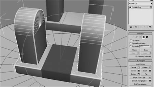
Figure 2-702
34. Select the left stanchion. Under the Edit Geometry rollout, click Detach.

Figure 2-703
35. Select the borders on both stanchions and Cap them.
Day 14: Building the Boom Assemblies
1. Switch to the Right view and, using AutoGrid, create a Cylinder to match the curve of the frontmost stanchion.
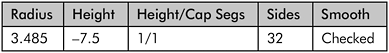

Figure 2-704
2. Switch to the Top view and center the cylinder between the vertical parts of the stanchion; adjust the position and height of the cylinder until the ends of the cylinder touch the inside edges of the stanchion, but do not penetrate (my final height was –9.13).
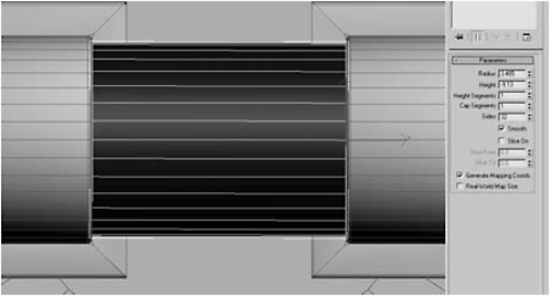
Figure 2-705

Figure 2-706
3. Convert the cylinder to an Editable Poly and center its pivot.
4. Switch back to the Top viewport, select all the edges (32 in all), and click Connect. A Segments setting of 1 slices the rod in half.
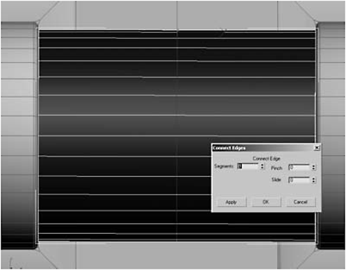
Figure 2-707
5. Select the polygons on the left side and delete them.
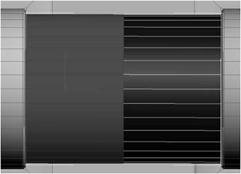
Figure 2-708

Figure 2-709
6. Select the 32 edges remaining, activate the Slice Plane, and make a slice where shown in Figure 2-710.

Figure 2-710
7. Object-select the cylinder, add a Symmetry modifier to its stack, switch the Mirror Axis to Z, and rename it lower_boom.
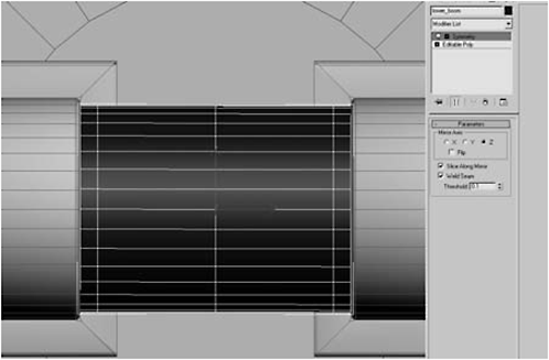
Figure 2-711
8. Select the front 26 polygons and Group Extrude them 15.0.
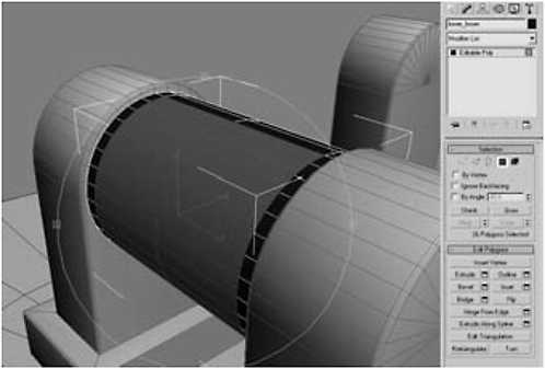
Figure 2-712
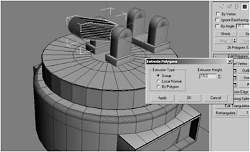
Figure 2-713
9. Switch to the Local coordinate system and scale the polygons down to 0 in the Z axis.

Figure 2-714
10. Delete the front polygons, then switch to the Right view and position the pivot as shown using the Move and Rotate tools.

Figure 2-715
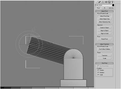
Figure 2-716
Don’t Forget: You have to change the pivot; otherwise, when you mirror, Max will try to mirror from the axle part by the stanchion instead of the boom’s middle. This is a mistake I always make and for some reason am always surprised when my mirrors don’t work!
11. Mirror a copy in the X axis.

Figure 2-717

Figure 2-718
13. Select one of the seam’s edges and Loop it.
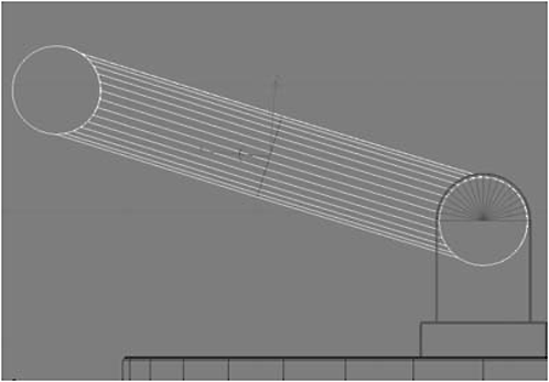
Figure 2-719
14. Chamfer the edge by 1.5.

Figure 2-720
15. Rotate around until you can see the top edge, then select the middle seam between the edges you chamfered.
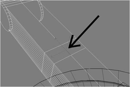
Figure 2-721
16. Chamfer the edge by 3.0.

Figure 2-722
17. Select the center edges.

Figure 2-723

Figure 2-724
Urgent: We have a problem here. We have two triangular polygons. Now we could just split it straight across, but that would double our problem by giving us four triangles. What we need to do is connect the three middle edges. This will turn the two three-sided polygons into two four-sided polygons.
19. Select the three middle edges and click Connect.

Figure 2-725
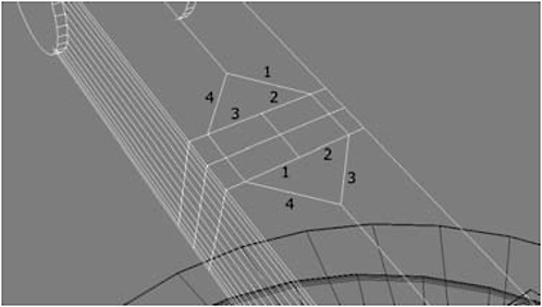
Figure 2-726
20. Select the four polygons on the edges and Extrude them by 2.5.
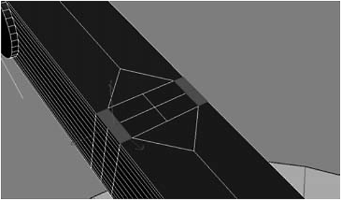
Figure 2-727

Figure 2-728
21. Select the lower two polygons, delete them, and then Hinge From Edge 180 with 10 Segments, using the edges indicated by the arrows in Figure 2-730.

Figure 2-729
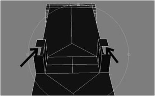
Figure 2-730

Figure 2-731
22. Select the vertices and Weld them.

Figure 2-732
23. Object-select the boom and Mirror it in the XY axis with an Offset of –0.45.

Figure 2-733

Figure 2-734
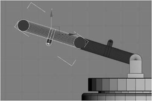
Figure 2-735
25. Rename the clone upper_boom and hide it.
26. Zoom in on the upper joint, select the 52 polygons shown in Figure 2-736, and then delete them.

Figure 2-736

Figure 2-737
27. Switch to Polygon selection mode, click the Create button, and select each of the vertices clockwise until the inside of the joint has been capped.
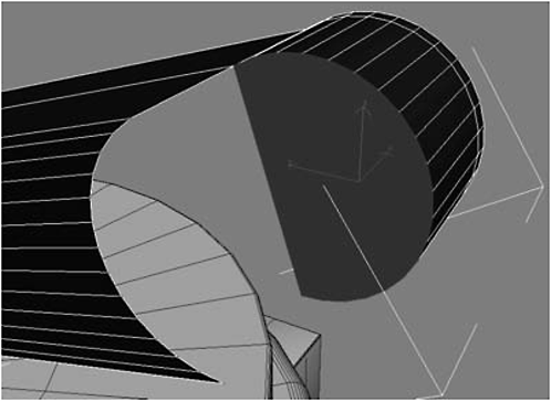
Figure 2-738
28. Bridge the upper and lower edges.
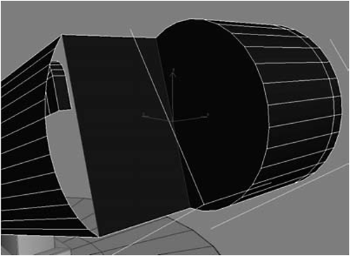
Figure 2-739
29. Select the left and right edges and then click Connect and enter 12 for Segments.

Figure 2-740

Figure 2-741

Figure 2-742
31. From the main menu, select Customize, and from the Customize menu, select Grid and Snap Settings.
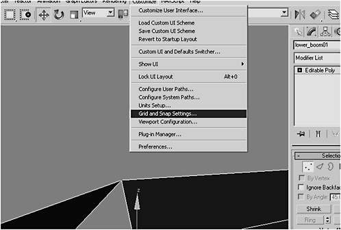
Figure 2-743
FYI: Snap allows you to very accurately align objects and subobjects. This is particularly useful when you need to superimpose objects for the purpose of welding them.
32. Make sure only Vertex is selected and close the dialog.

Figure 2-744
FYI: As you can see, you have a variety of snapping options available to you. You can select more than one and toggle through them using Alt+S. You might want to do that if you’re a power user working on some really complex geometry. Me? I like to K.I.S.S. (Keep It Simple, Stupid). So I only turn on one snap type at a time. Personally, I find Vertex to be the most useful.

Figure 2-745
34. Select the Move tool and select the vertex you want to snap.
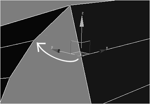
Figure 2-746
Message: Note that a cyan cross appears over the vertex, indicating that Max is ready to snap that vertex to whichever one you select.
35. Hold down the left mouse button and drag the cross until the vertex is superimposed over the one indicated by the white arrow in Figure 2-746 and release the mouse button; the vertices will snap together.

Figure 2-747
36. Select those two vertices and Weld them together.
37. Snap and Weld the remaining vertices until the gap has been closed.

Figure 2-748
FYI: What we’ve done here is to create a socket that the joint can turn in. Now we have to sculpt the middle verts to match the outer ones; however, since you won’t really see the inner vertices, it’s not essential that they be perfectly aligned.
38. Turn off Snap and use the Move tool to align the center vertices with the outer vertices; it may help to do this in the Left view in wireframe mode.
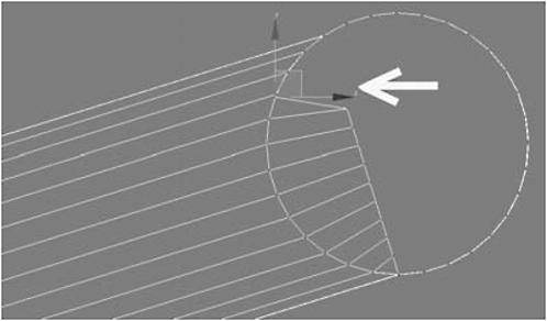
Figure 2-749
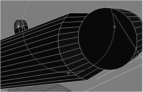
Figure 2-750
FYI: Now you can better see what we were doing in the last few steps. We now have a nicely formed socket that our upper_boom can move in.
39. Unhide the upper_boom.
Figure 2-751
Message: The booms fit together nicely. The only problem is that the right side of the upper_boom is on top of the right side of the lower_ boom. Fortunately, that’s easy to fix.

Figure 2-752
40. Hide the lower_boom, select all the polygons making up the duplicate right joint on the upper_boom, and delete them.
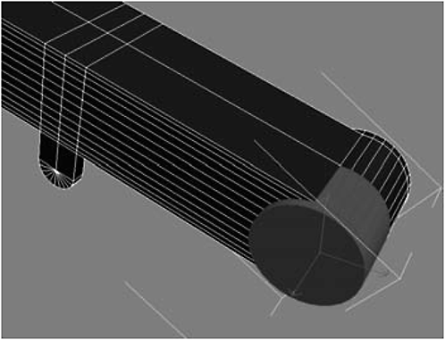
Figure 2-753

Figure 2-754
41. Repeat steps 27-38 to complete the joint.
42. Now when you unhide the lower_boom, you’ll see that they fit together perfectly.
Figure 2-755
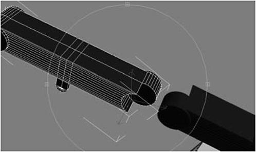
Figure 2-756
Message: Your booms should still be fitted together; I moved mine apart to show you how they fit. However, if you moved yours, move them back together now.
43. Select the polygon in the center of the lower_boom’s joint.

Figure 2-757
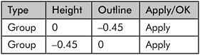
Figure 2-758

Figure 2-759

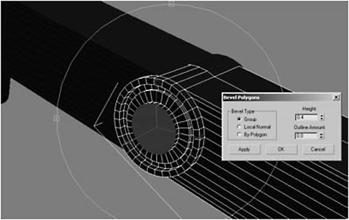
Figure 2-760
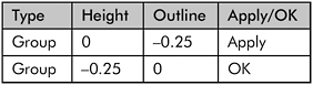

Figure 2-761
45. Apply your Clay material to the lower_boom and do a test render.

Figure 2-762
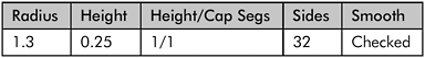
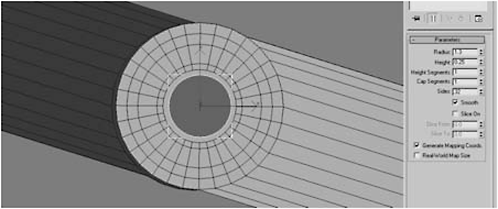
Figure 2-763
47. Convert the cylinder to an Editable Polygon.
48. Pick a polygonon the top and a matching polygon on the bottom of the cylinder. Go one polygon to the left and right of these polygons and use the Cut tool to make a slice across the top as shown in Figure 2-764.

Figure 2-764
49. Select the left and right polygons created by the cuts you made.

Figure 2-765
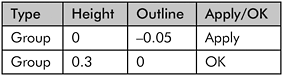

Figure 2-766

Figure 2-767
51. Rotate around the back of the screw you’ve just created, delete the back-facing polygon, add the Clay material to the screw, and Select and Link it to the lower_boom.
52. Do a test render.

Figure 2-768
53. Switch to the Right view and zoom in on the joint.
54. Using AutoGrid, create a Gengon on the lip next to the screw.


Figure 2-769
55. Convert the gengon to an Editable Polygon, delete the back-facing polygons, and move the gengon’s pivot to the center of the joint.

Figure 2-770
56. Add the Clay material to the gengon, turn on Angle Snap, hold down the Shift key, Rotate 60 degrees, and enter 5 for the Number of Copies.

Figure 2-771
57. Select and Link the gengons to the joint and do a test render.

Figure 2-772
Message: Notice how simply applying gengons (nuts) and a screw can make something look mechanical.
58. Repeat steps 26-57 for the mating joint on the upper_boom.
59. Select the screw (cylinder) and nuts (gengons) and, in the Top view, move their pivots to the middle of the boom.

Figure 2-773
60. Click Mirror and copy them in the X axis.
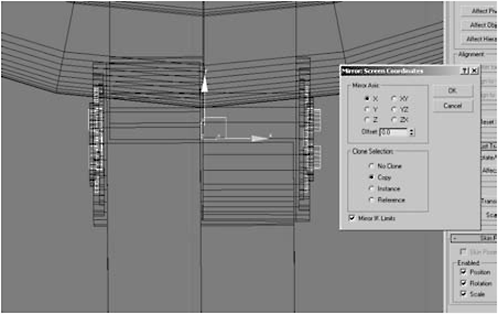
Figure 2-774
Fire Drill: Double-check the Left view to make sure the nuts and screw are properly aligned on the left side. You can think you have everything perfectly aligned and then find you don’t. If they aren’t aligned properly, just use the Move tool to position them before you Select and Link.

Figure 2-775
61. Select and Link the upper_boom to the lower_boom, Select and Link the lower_boom to the boom_mounts, and Select and Link the boom_mounts to the main_turret.
62. Select the lower_boom and move its pivot point to the center of the joint, beneath the mount.

Figure 2-776

Figure 2-777
64. Polygon-select the mounts on top of the lower_boom.

Figure 2-778
65. Click Detach As Clone.
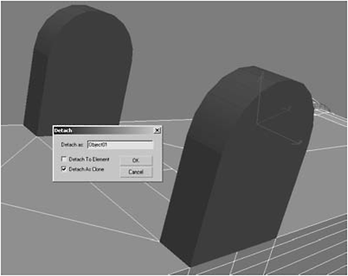
Figure 2-779
66. Click Affect Pivot Only and center to the object.
67. Switch to the Local coordinate system, click Mirror, mirror in the Y axis, choose No Clone, and use an offset value that gets the mount close to the bottom edge of the boom (e.g., –10.27).
FYI: No Clone is selected here because we merely want to flip the axis of the mounts without making a copy. We already made a copy with the Detach procedure.
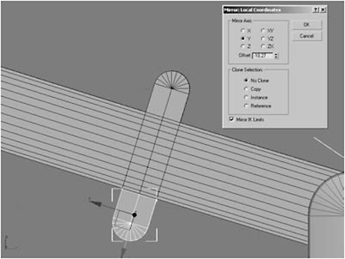
Figure 2-780
68. Edge-select the seam between the mounts, on the underside of the lower_boom.

Figure 2-781

Figure 2-782
70. Select the three edges and click Connect, then highlight the polygons created by the chamfering and delete them.
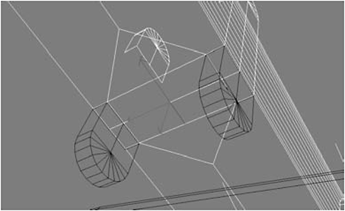
Figure 2-783
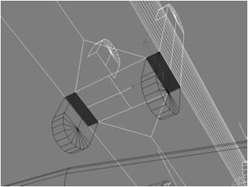
Figure 2-784
71. Attach the mounts to the lower_boom, select the vertices where the mount connects to the boom, and Weld them together.

Figure 2-785
Day 15: Building the Hydraulics
1. Switch to the Bottom view and hide everything but the upper and lower booms.
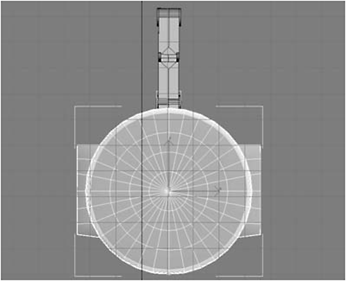
Figure 2-786
2. Using AutoGrid, create a Sphere with a Radius of 1.8 and 32 Segments between the hydraulic mounts on the lower_boom.
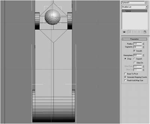
Figure 2-787
3. Move the sphere up and Rotate it 90 degrees in the Y axis, so that the poles of the sphere are facing the mounts.

Figure 2-788
4. Change the sphere’s Hemisphere value to 0.5.
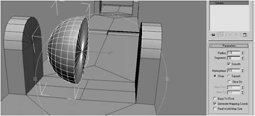
Figure 2-789
5. Convert the sphere to an Editable Polygon, delete the back-facing polys, and add a Symmetry modifier to the stack.
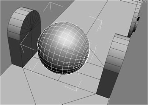
Figure 2-790
FYI: So why didn’t I just leave it whole in the first place? Because I’ll be creating axles out of the sides of the sphere. This way, I only have to do it on one side.
6. Select the first four rings of polygons (128 total).

Figure 2-791
Don’t Forget: To subjobject-select (polygon-select) when you’ve applied a modifier, you have to open up the Editable Poly rollout beneath the modifier. Also, Max does not automatically show you the results of modifiers. You have to press the little test tube icon the arrow is pointing to in Figure 2-791.
7. Delete the selected polygons and cap the border.
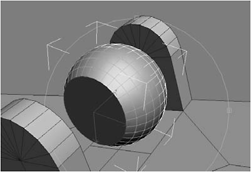
Figure 2-792
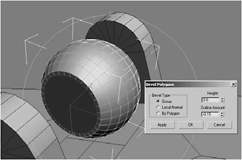
Figure 2-793

Figure 2-794
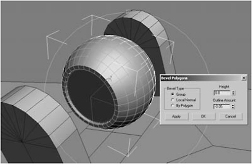
Figure 2-795
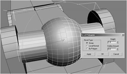
Figure 2-796
9. Use the Rotate tool to straighten the joint so that it is properly positioned between the mounts.

Figure 2-797
10. Do a test render.

Figure 2-798
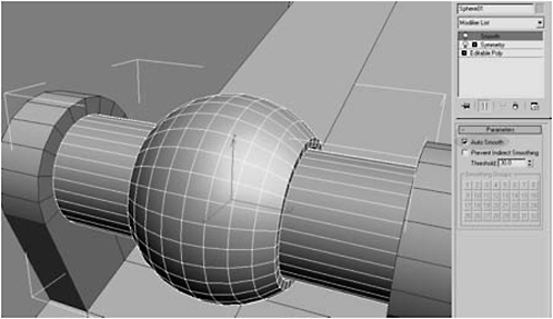
Figure 2-799
12. Switch to the wireframe mode. Select the end polygon and delete it (it’ll be automatically deleted from the other side).

Figure 2-800
13. Switch to the Bottom view, hold down the Shift key, and move the axle to the upper mount to make a clone.
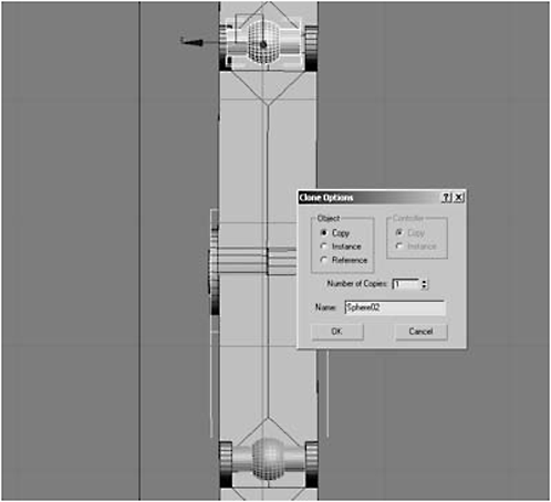
Figure 2-801
Figure 2-802
15. Select the six by six block of polygons in the center of the axle.
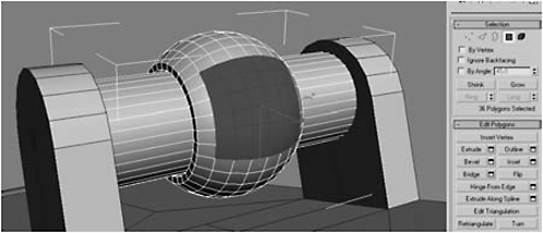
Figure 2-803
16. Group Extrude the polygons by 0.3.

Figure 2-804
17. Scale the polygons down to 0 in the Local Z axis to flatten them.

Figure 2-805
18. Select the top row of seven vertices and scale them down to 0 in the Local Y axis to flatten them. Repeat for the bottom seven. Repeat this for all the polygons (scaling in X, Y, or Z) until you get a flat surface with roughly flat tops and sides.
Message: Don’t sweat trying to make them ruler straight. Just get them as close as you can without spending hours on it. After all, nothing manufactured is perfectly straight. Look at the things around you. They have bumps, and dents, and warps. The more perfect you make your geometry the less real it will look. For example, mine has a slight twist to it and I like that. It makes it look like the metal was poorly tempered.

Figure 2-806

Figure 2-807

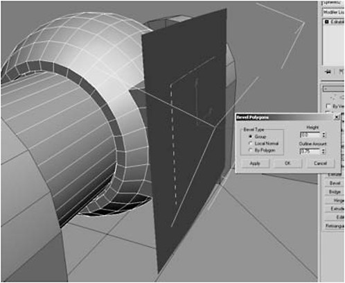
Figure 2-808

Figure 2-809
20. Delete the selected polygons and Cap the border.

Figure 2-810
21. Select and Link to the lower_boom.
22. Using AutoGrid, create a Cylinder in the center of the plate you just made.


Figure 2-811
23. Convert the cylinder to an Editable Polygon, select and delete the polygon facing the plate, and Attach the cylinder to the plate.

Figure 2-812
24. Select the front polygon and click Bevel Settings:
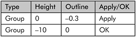
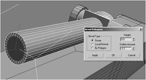
Figure 2-813

Figure 2-814
25. Although you can’t see it, the polygon is still selected; click Detach to detach it as an object, and name the new object piston_rod.
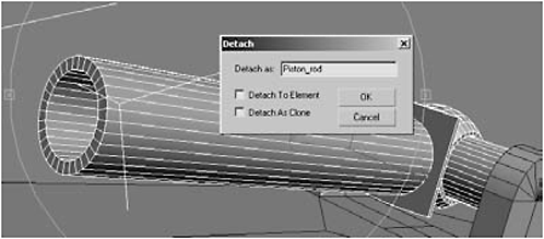
Figure 2-815
26. Switch to the Bottom view and move the piston_rod around 31 in the Y axis, until it is against the upper axle.

Figure 2-816
Message: The normal will be flipped away from you, making it invisible. Nice, huh? However, since your Move gizmo is attached to the object, you can use the gizmo to make your best guess. At this point, you don’t need to be dead on anyway.
27. With the piston_rod polygon selected, click Flip to flip the normal, so that the normal is facing toward the piston; now you should see it with no problem.

Figure 2-817
28. Extrude the piston_rod polygon until it is a little over the center of the piston (~28).
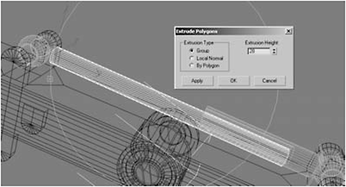
Figure 2-818
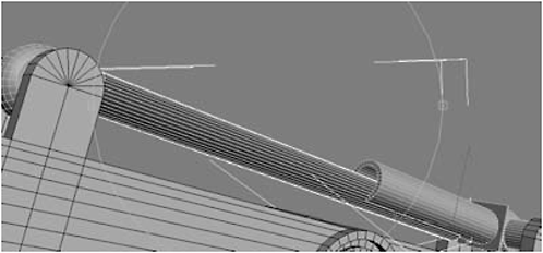
Figure 2-819
29. Click Affect Pivot Only and use the Rotate and Move tools to position the pivot at the end of the cylinder.
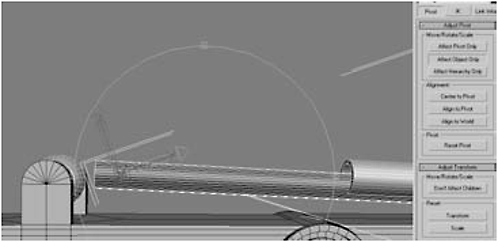
Figure 2-820

Figure 2-821

Figure 2-822

Figure 2-823
31. Align the rod so it fits into the piston.
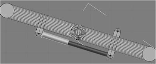
Figure 2-824

Figure 2-825
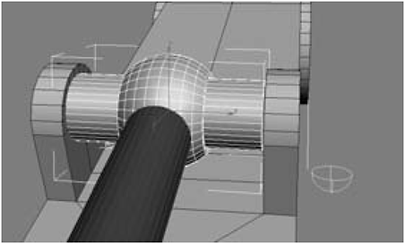
Figure 2-826
32. Under the Create panel, select Compound Objects, select Boolean, select Union as the Operation, click Pick Operand B, and click piston_rod.

Figure 2-827
33. Change the renamed compound object back to piston_rod, convert it to an Editable Polygon, add a Smooth modifier to the stack, click Auto Smooth, and then convert it to an Editable Polygon to collapse the stack.
34. Under the Hierarchy tab, click Affect Pivot Only, then make sure that the pivot is properly centered on the joint with the Y axis pointing straight at the other joint.
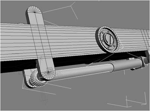
Figure 2-828
35. Repeat the previous step for the other joint, making sure its pivot is properly aligned and facing the other joint.

Figure 2-829
FYI: To properly link these two parts so they move together, their pivots have to be facing each other. Now comes the fun part — the linking.
36. On the Control panel, click the icon that looks like a tape measure (Helpers), click the Dummy button, and then create a dummy on the lower mount.

Figure 2-830
FYI: A dummy is an object that does not render. You can use a dummy for a variety of purposes, but in this instance we’ll be using it to align the two parts of the hydraulic piston.
37. Position the dummy in the center of the lower joint.
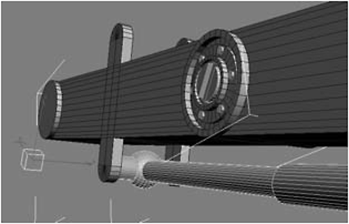
Figure 2-831

Figure 2-832
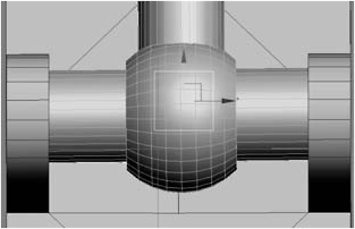
Figure 2-833

Figure 2-834
FYI: When orienting a dummy object, it is often very helpful to use the Align to Object feature (icon to the right of the Mirror Geometry button) and align the object to the target object’s pivot point (which in this case is the axle).
38. Select and Link the dummy to the lower_boom.
39. Select the upper part of the piston and click on the Motion tab (looks like a wheel) on the Create panel.
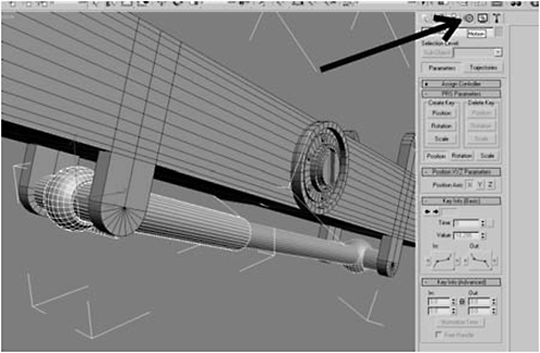
Figure 2-835

Figure 2-836
FYI: Controllers govern an object’s motion, scale, or rotation. In our case, we want to control the rotation of the upper part of the piston when we rotate the upper_boom by constraining the movement of the upper part to the movement of the lower part of the piston.
41. Click the Assign Controller button (its icon is the ? button) to open the Assign Rotation Controller dialog, pick LookAt Constraint, and then click OK.
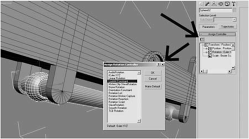
Figure 2-837
FYI: The LookAt constraint does what it says; it constrains the movement of an object so it is always oriented toward the target. This constraint is generally used in conjunction with eyes and a dummy object. The eyes are constrained to the dummy object, and moving the dummy object causes the eyes to follow. However, this constraint is also extremely valuable for making interlocking parts like pistons.
Don’t Forget: The parts of the pistons have to be Select and Linked to their respective booms; otherwise, when you move the boom, the piston won’t follow. The LookAt constraint only makes sure the two parts of the pistons look at each other.
42. Under the LookAt Constraint rollout, click Add LookAt Target (and nothing seems to happen). Hit the H key to open the Pick Object list, pick the dummy object (Dummy01), and then click the Pick button.
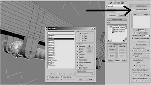
Figure 2-838

Figure 2-839
Fire Drill: Invariably, the object you’re adding the constraint to will orient in the wrong direction. And this time is no exception. Fortunately, it is merely a question of realigning the axis of the object being constrained.
43. Under the LookAt Constraint rollout, you’ll see a check box labeled Keep Initial Offset. Check it and the piston will return to its proper orientation.
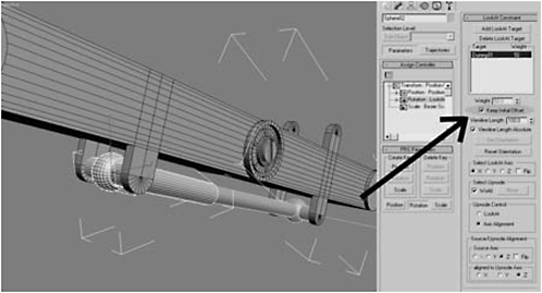
Figure 2-840
FYI: Once the LookAt constraint has been applied, a blue line will appear, indicating the sight line of the constraint. Now that we have the LookAt constraint set up for one part of the piston, we’ll have to set up the constraint for the other one.
44. Click the part of the piston attached to the lower_boom, add a LookAt constraint, click the Add LookAt Target button, hit H, and select the top dummy.

Figure 2-841
Message: Now when you rotate the upper_boom, the piston should slide in and out like a real piston. If not, first check to make sure the dummies and piston parts are attached to their respective booms. Then, check and be sure each object is aimed at the correct dummy object.
45. Hide everything except the upper part of the piston (i.e., the larger part).

Figure 2-842
46. Arc Rotate around the end opposite the joint and create a Tube over the piston cylinder.

Figure 2-843

Figure 2-844
47. Move the tube to the end of the cylinder and convert the tube to an Editable Polygon.
48. Using AutoGrid, create a Cylinder in the upper-right corner of the plate and extending out to the edge of the tube.
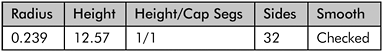

Figure 2-845
49. Make a clone of the cylinder in the remaining three corners and then Attach them and the tube to the piston.
Figure 2-846


Figure 2-847
51. Clone the tube three times and place each over the top of each cylinder (you may need to scale each one a bit so that it contacts the surface of the larger tube), then Attach each tube and cylinder to the piston.
Figure 2-848
52. Unhide the piston_rod, mounts, booms, etc., and do a test render.
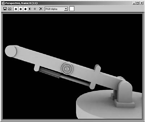
Figure 2-849

Figure 2-850
54. Clone it. Click the Motion tab, and under Assign Controller select Rotation.

Figure 2-851
FYI: As you can see from the blue line, the clone is constrained to look at whatever the original was looking at. To properly position it, you’ll have to break the clone’s constraint. This step is unfortunate because it necessitates removing the LookAt constraint only to redo it. Unfortunately, Max doesn’t provide a way to switch LookAt targets without removing the old one first.
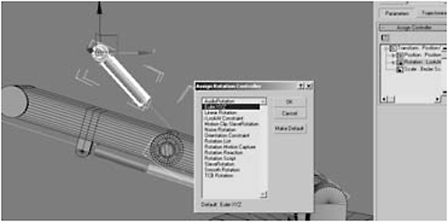
Figure 2-852

Figure 2-853
Fire Drill: As you can see, removing a constraint really jacks up your model’s orientation. You’ll need to reorient the clone and then readjust the pivot.
56. Use the Move and Rotate tools to adjust the piston_rod and move it into place.
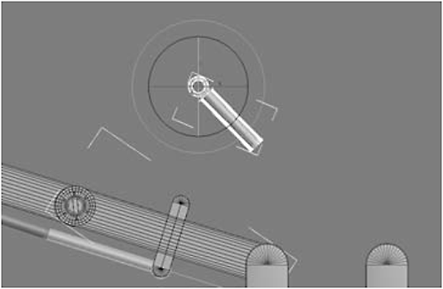
Figure 2-854
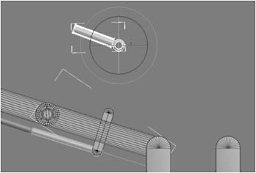
Figure 2-855

Figure 2-856
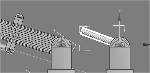
Figure 2-857

Figure 2-858
58. Clone the piston_rod.
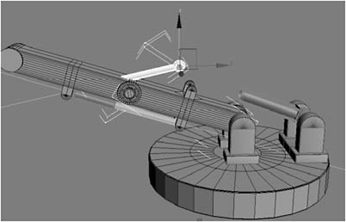
Figure 2-859
59. Open the Motion tab and replace the LookAt constraint with a Euler XYZ.
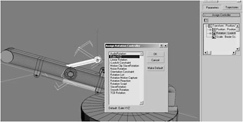
Figure 2-860

Figure 2-861
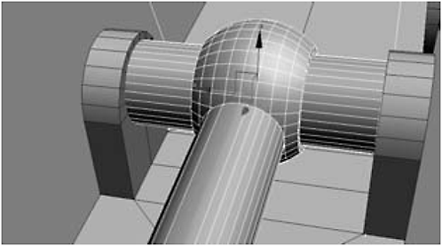
Figure 2-862
61. Scale the rod by 125 percent.
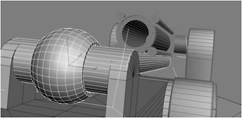
Figure 2-863
62. Select all the vertices on the sides of the axle and move them inside the mount.
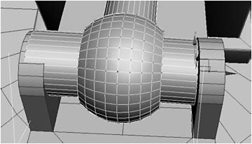
Figure 2-864

Figure 2-865
63. Select the vertices on the end of the rod and move them to reduce the length of the rod so it fits inside the piston.
Figure 2-866
Figure 2-867
65. Switch the coordinate system to Gimbal, select the vertices on the end of the piston, and move them in the Y axis until they clear the other mount.

Figure 2-868

Figure 2-869
FYI: Because we are temporarily using Euler XYZ for our rotation constraint, the other coordinate systems will not work properly. Switching to Gimbal gives you a coordinate system that will allow you to smoothly move the vertices in a line.
66. Select the vertices making up the end of the piston and the supporting rods.
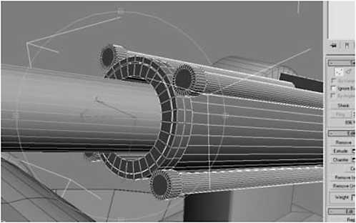
Figure 2-870

Figure 2-871
68. Select and Link the rod and the piston to the turret.
69. Create a dummy for each part of the new piston, align each to the respective piston, then Select and Link the dummies to the boom and mount.
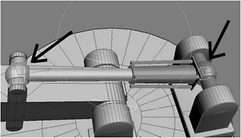
Figure 2-872
70. Select the piston_rod, add a LookAt constraint, check Keep Initial Offset, and target the dummy (Dummy04) positioned at the rear of the piston cylinder.
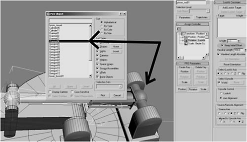
Figure 2-873
Don’t Forget: You have to check Keep Initial Offset or the object will not be properly aligned.
Message: Now if you move the booms, the pistons will work properly. However, if you hyperextend the booms, the pistons will come apart. Having said that, if you hyperextend the boom, you can rotate them right through the entire model. An extensive discussion of rigging and animation are beyond the scope of this book; however, the key to getting this model to behave is to add additional constraints on its movement, so that parts like the booms are prevented from moving past a certain point.
72. In the Top view, create a Box on both sides of the boom, atop the main turret.


Figure 2-874
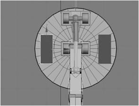
Figure 2-875
73. Convert the boxes to Editable Polygons, delete the underside faces, and Attach them to the main turret.
74. Select the top 18 polygons that make the top curve on the outside of the right stanchion.

Figure 2-876
75. Extrude the polygons by 0.8.

Figure 2-877
76. Select the four edges of the boxes you created, click Connect, and enter 2 for Segments.

Figure 2-878

Figure 2-879

Figure 2-880


Figure 2-881

Figure 2-882
78. Create a Geosphere with a Radius of 2.45 and 4 Segments, check Hemisphere, convert it to an Editable Polygon, and delete the polygons beneath the hemisphere.
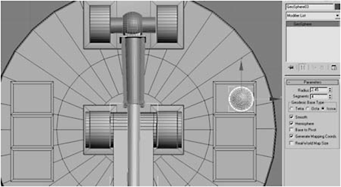
Figure 2-883


Figure 2-884
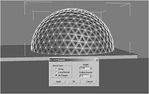
Figure 2-885
80. Border-select the bottom of the hemisphere, click Create Shape From Selection, and name it seal.
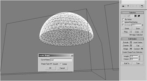
Figure 2-886
81. Select seal and check Enable In Renderer and Enable In Viewport; then change the Thickness to 0.3 and convert it to an Editable Polygon.

Figure 2-887
82. Attach the seal to the geosphere, switch to the Top view, and make six clones (one on top of each of the polygons you made).

Figure 2-888
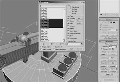
Figure 2-889

Figure 2-890
84. Switch to the Top view and create a Cylinder at the bottom-left corner of the middle box.
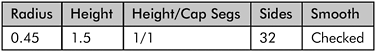

Figure 2-891
85. Convert the cylinder to an Editable Polygon, delete the downward-facing polygon, select the top polygon, enter an Extrusion Height of 0.15, and hit Apply nine times.

Figure 2-892
86. Move the cylinder’s pivot point up to the edge at the start of the first extrusion, and apply a Bend modifier to the stack (Bend –90 in the Z axis, check Limit Effect, and enter an Upper Limit of 1.0).

Figure 2-893

Figure 2-894
87. Convert the cylinder to an Editable Polygon to collapse the stack, then, using the Move tool, pull the polygon about halfway to the stanchion base by eye.

Figure 2-895

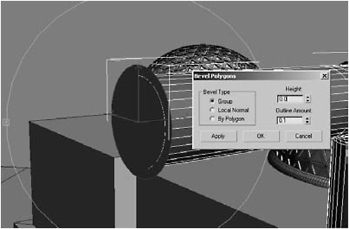
Figure 2-896
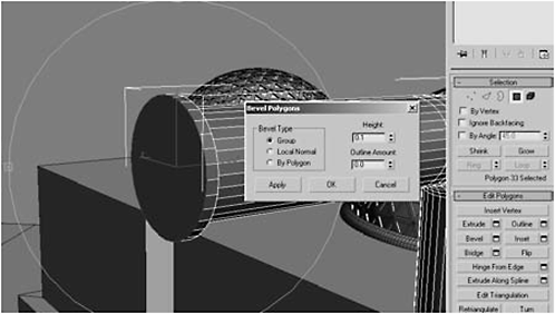
Figure 2-897

Figure 2-898

Figure 2-899

Figure 2-900
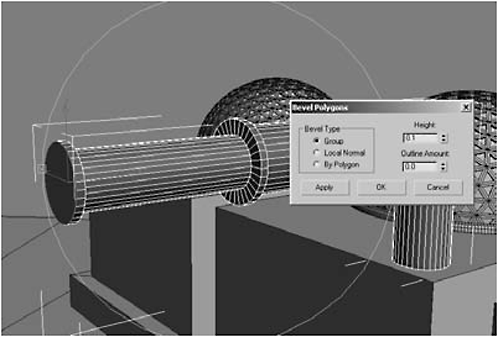
Figure 2-901

Figure 2-902
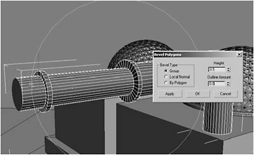
Figure 2-903
89. Switch to the Front view and use the Move tool to move the polygon until it is just below the upper part of the stanchion.
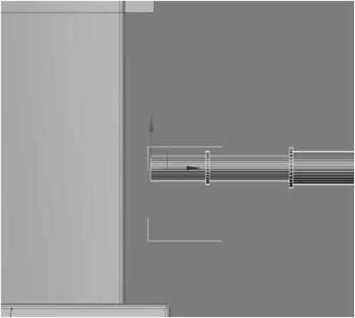
Figure 2-904
90. Extrude by 0.1 ten times.

Figure 2-905
91. Move the pivot point to prepare for a bend.

Figure 2-906
92. Add a Bend modifier to the stack with an Angle of –90 in the X axis, and with the effect limited to a Lower Limit of –0.56. Convert to an Editable Polygon.

Figure 2-907

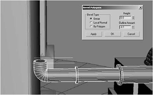
Figure 2-908

Figure 2-909
Message: I used a height of 3.5, but use whatever height you need for the tube to be flush with the bottom surface. Don’t forget to delete the facing polygon!
94. Select the border between the pipe and the box, click Create Shape From Selection, check Enable In Renderer and Enable in Viewport, check Generate Mapping Coordinates, and reduce the Thickness to 0.16.

Figure 2-910
95. Select Cylinder06, add a Smooth modifier to its stack, turn on Auto Smooth, and convert it to an Editable Polygon to collapse the stack.
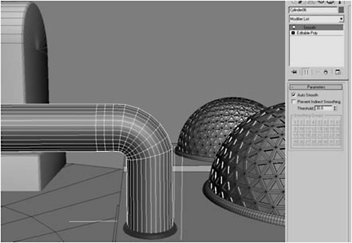
Figure 2-911

Figure 2-912
97. Switch to the Top view, select the pipe, and Shift-move it in the Y axis. Enter 3 for the Number of Copies.

Figure 2-913
98. Do a test render.

Figure 2-914
99. Select the four pipes you just made, switch to the Top view, and Mirror copy in the X axis, with an Offset of –19.17 (or whatever number works best to align the pipes on the left side).

Figure 2-915

Figure 2-916

Figure 2-917
100. Select the main_turret, click Attach List, and attach the cylinders and gengons you made as part of the hydraulic system.

Figure 2-918
101. Do a test render.
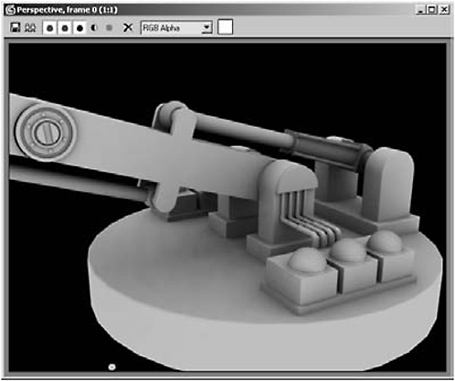
Figure 2-919

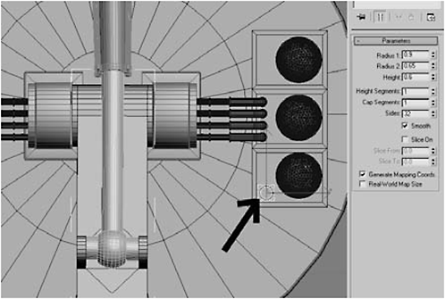
Figure 2-920
103. Make a clone of the tube and attach it to the mount for the piston on the upper_boom.
Figure 2-921
104. Switch to the Top view and, using AutoGrid, create a Hose in the center of the tube you created on the top of the box.
105. Under Hose Parameters, switch the End Point Method from Free Hose to Bound to Object Points.
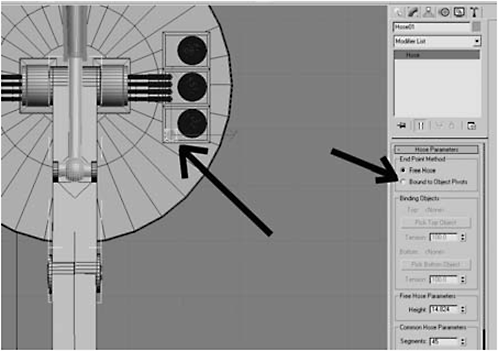
Figure 2-922
106. When you switch from Free Hose to Bound to Object Points, the Binding Objects area becomes active. Click Pick Top Object, hit H to open the object list, select Tube04 (or whatever you called the tube you placed on the piston mount), and click Pick.

Figure 2-923
107. Click Pick Bottom Object, hit H for the object list, select Tube03 (or whatever you called the tube you placed on the box), and click Pick.

Figure 2-924
Figure 2-925
FYI: Hose is way cool because you don’t have to rig it. By setting the top and bottom binding objects, you’re telling Max how to make it behave like a real hose. The geometry will stay fixed to those binding objects and the geometry of the hose will stretch to match the motion of the binding objects. How cool is that? But you don’t have to limit yourself to making hoses; you can use the Hose object for a rope if you’re making a pirate ship.

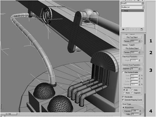
Figure 2-926
FYI: There are four required bound hose settings. The first two are tension settings. Experiment with different values; not only do they control slack, but they also control the angle at which the hose connects to the binding objects. The third value is the number of segments in the hose. Like other objects, the more segments you have, the smoother the result, but the more of a drag it will put on your machine. The Hose Shape section (three values grouped together) determines the overall shape and size of the hose. The Flex Section Enable section is used when you want to make a segmented hose. We want a smooth hose, so I left it unchecked.
109. Select and Link the tubes to mount them to the upper_boom and main_turret.
110. Make sure the hoses are connected to where they should be.
111. Repeat steps 102-110 for the left side of the model.
Fire Drill: Depending upon how asymmetric your particular model is, you may have to tweak the tension settings on the clone to get it to look right. Also check to make sure all of your objects are where they ’re supposed to be. If you really want to be daring, use very different settings to get an asymmetrical look.
112. Select All, add your Clay material to every object, and do a test render.

Figure 2-927
FYI: All the settings should be the same as the previous hoses. The only thing that should be different for the rear is that the top and bottom tensions should be quite different.
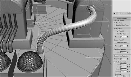
Figure 2-928
Fire Drill: Picking the proper tensions can be frustrating. Just be patient and keep tweaking the upper and lower tensions. If you’re still not getting the results you think you should, check the pivot points of the binding objects. You may need to tweak those too. For example, to get my rear hose to work right, I had to rotate the binding objects’ pivots.
Figure 2-929
Day 16: Final Detailing
1. Switch to the Right view and polygon-select the middle polygons of the main_turret.
Figure 2-930
2. Click Bevel Settings:


Figure 2-931

Figure 2-932
4. Click Bevel Settings:
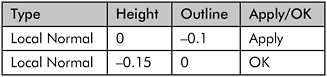

Figure 2-933

Figure 2-934

Figure 2-935

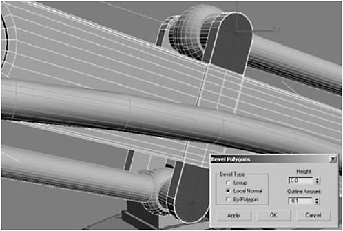
Figure 2-936

Figure 2-937

Figure 2-938
7. Convert it to an Editable Polygon, select the back-facing polygons and delete them, and make clones on both sides, for a total of four.
Figure 2-939
8. Attach the hemispheres to the boom.
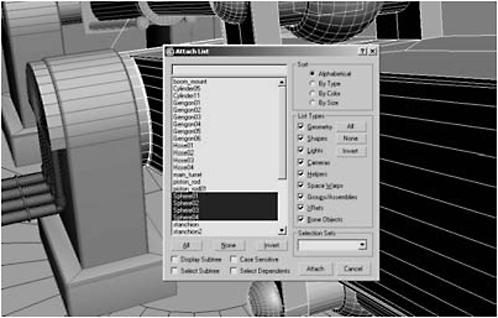
Figure 2-940

Figure 2-941


Figure 2-942

Figure 2-943
10. Select the polygons of the uppermost joint on the right side of the upper_boom.

Figure 2-944
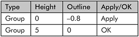

Figure 2-945
Figure 2-946
12. Group Extrude by 1.0 and hit Apply nine times.

Figure 2-947
Figure 2-948

Figure 2-949
14. Click Detach, choose Detach As Object, and name it eye_axle.

Figure 2-950
15. Move the pivot point to the fifth segment.

Figure 2-951
16. Add a Bend modifier to the eye_axle with an Angle of –90, Direction of 40, in the Z axis, with the effect limited to an Upper Limit of 5.0.

Figure 2-952
17. Convert it to an Editable Polygon and slide it inside the joint as shown in Figure 2-954.

Figure 2-953
18. Unhide the eye_pod and add the Clay material to it.

Figure 2-954
19. Select the eye_pod and center the pivot.
Figure 2-955

Figure 2-956
21. Select the polygon at the end of the eye_axle.
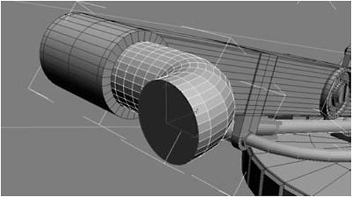
Figure 2-957
22. Extrude it by 1.0 ten times.

Figure 2-958

Figure 2-959
24. Extrude the polygon by 1.0 and Rotate it.

Figure 2-960

Figure 2-961
25. Repeat the last step until you achieve a 90-degree angle.
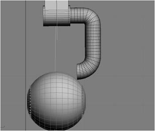
Figure 2-962
26. Position the eye_pod so that the hole in it is aligned with the end of the eye_axle.
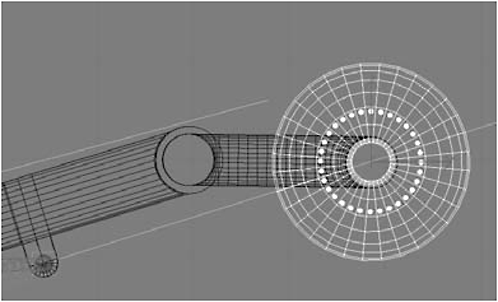
Figure 2-963

Figure 2-964
27. Select the polygon at the end of the eye_axle (facing the opening of the eye_pod), switch to the Left view, click Bevel Settings, and adjust the Outline Amount until you can look through the hole in the eye_pod and see that the polygon will just fit (mine is –0.75). Click OK.
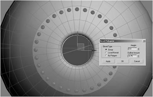
Figure 2-965
28. Switch to the Top view and Extrude the polygon until it is most of the way through the hole in the eye_pod, but not the entire way (~17.75).
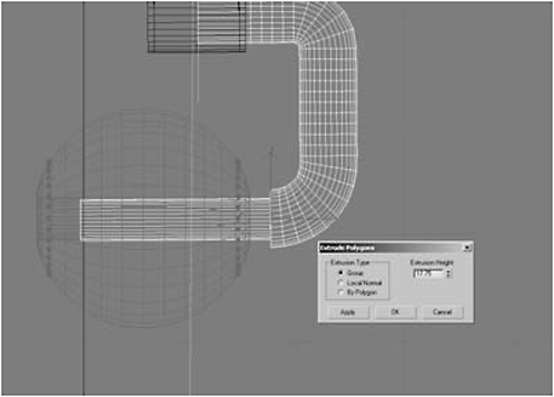
Figure 2-966
29. Move the eye_pod until it is seated against the eye_axle.

Figure 2-967
30. Select and Link the eye_pod to the eye_axle and Select and Link the eye_axle to the upper_boom.
31. Center the pivot of the eye_pod and move the eye_axle pivot to the joint that connects it to the upper_boom.
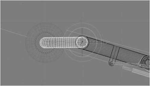
Figure 2-968
32. Unhide the eye, position it on top of the eye_pod, and scale it to the size shown in Figure 2-969.
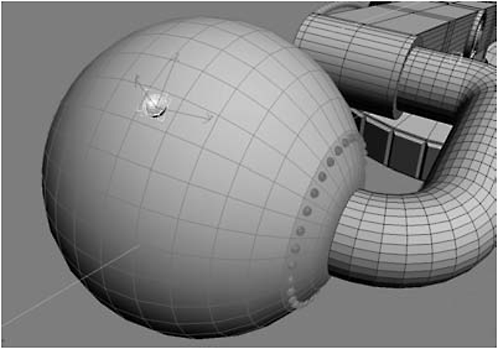
Figure 2-969

Figure 2-970
34. Object-select the eye. Under the Create panel, select Compound Objects, and under Object Type, press the Scatter button.
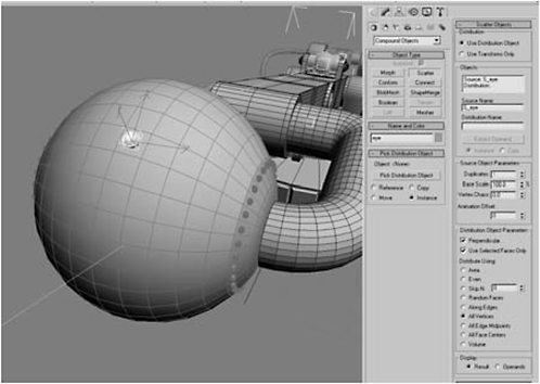
Figure 2-971
35. Make sure that Instance is selected, Use Selected Faces Only is checked, and All Vertices is selected.

Figure 2-972
FYI: Scatter will use the faces you selected on the eye_pod and create instances at each vertex in that selection.
36. Select Pick Distribution Object, hit H, and select eye_pod.
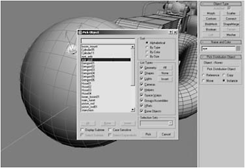
Figure 2-973

Figure 2-974
37. Convert to Editable Polygon, then select eye_pod and delete it.

Figure 2-975
FYI: You delete the eye_pod because you don’t need it anymore. It was just a matrix to create the scatter object.
38. Select and Link the eye object to the eye_axle.
39. Unhide All and add the Clay material to everything.
Figure 2-976

Figure 2-977

Figure 2-978
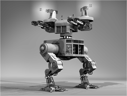
This is the battle mech we create in Chapter 3.