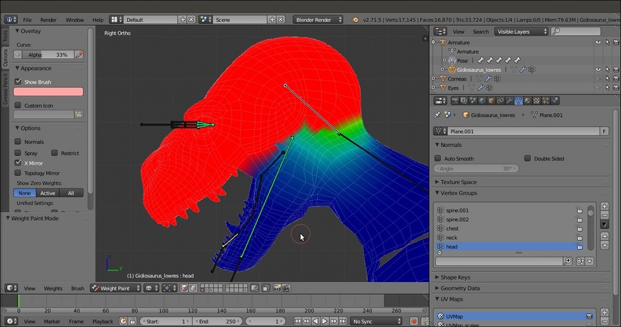
This technique is the oldest way to assign weights to vertices groups in Blender. Although now there are quicker ways to do the same thing, in some cases it's still one of the best approaches, which can reveal itself to be quite useful mainly because you can precisely select individual or edge-loops of vertices to be weighted inside a group.
Open the Gidiosaurus_autoweights.blend file we saved in the previous recipe.
- If necessary, press Ctrl + Tab to go out of Weight Paint mode.
- Select the Armature (which should still be in Pose Mode), press the A key twice to deselect-select all the bones, and press Alt + R and Alt + G to clear any rotation or position and restore the default pose.
- Press the 3 key on the numpad to go in to Side view; if necessary, the 5 key on the numpad to go in to Ortho view and the Z key to go in to Wireframe viewport shading mode.
- Select the Armature and disable the Shapes item; switch the draw mode of the bones to Stick and enable the third Armature layer to show the deforming bones.
- Save the file as
Gidiosaurus_skinning_01.blend.
First, we are going to use this technique to fix the head deformation as follows:
- Press Shift + B to draw a box around the head of the Gidiosaurus mesh and automatically zoom to it. Select the mesh and enter Edit Mode.
- Press the C key, through which the mouse cursor turns into a circle whose diameter can be set by scrolling the mouse wheel.
- Start to paint-select the vertices you want to add to the vertex group; in this case, we must add the whole upper head to the head vertex group and also include the upper teeth that were missing in the group.
- Be sure that the head vertex group is the selected one in the Vertex Groups subpanel under the Object Data window to the right, and that the Weight slider is set to 1.000; then, click on the Assign button.
- To quickly find a required vertex group, instead of slowly scrolling the list, just click on the grayed out little + icon at the bottom of the Vertex Groups window (just above the Assign button) to expand a blank search field and then write a few letters of the group's name followed by the Enter key:

The vertex group names search function
To get the complete list of vertex groups' names back, just erase the letters you wrote in the field and press Enter.
- Now, switch from Edit Mode to Weight Paint mode again, where the head vertex group colors show a lot different than before:

The modified "head" vertex group
- Now, while still in Weight Paint mode, go to the Tools tab under the Tool Shelf to the left of the screen and, in the Weight Tools subpanel, first click on the Normalize All button and then on the Clean button.
- Select the mand bone, go in to Edit Mode, and press A to deselect the vertices of the head vertex group. Select all the vertices of the jaw, including the bottom teeth; then go to the Vertex Groups subpanel to the right and deselect the tongue group by clicking on the, yes, Deselect button (we created the tongue vertex group chapters ago, during the modeling stage; otherwise, just deselect the tongue's edge-loops manually).
- Find and select the mand group and click on the Assign button.
- Go again in to Weight Paint mode and click on the Normalize All and Clean buttons under the Weight Tools subpanel:

The Weight Tools subpanel and the "mand" vertex group
- Now, go out of Weight Paint mode, select the mesh and, in the Vertex Groups subpanel, search for the eyelid_upper.L vertex group; enter Edit Mode and click on the Select button:

The selected eyelid_upper.L vertex group
We must get rid of all these vertices erroneously assigned to the vertex group by the Automatic Weights tool.
- Click on the Remove button and then press the A key to deselect everything.
- Repeat this for the eyelid_bottom.L, eyelid_upper.R, eyelid_bottom.R, and also for the eye.L and eye.R vertex groups.
- Zoom to the eyes area. Select an edge-loop (Alt + right-click) around the left eyelids and then press Ctrl and the + key on the numpad to extend the selection; press the H key to hide the selected vertices (this is simply to isolate the eyelids vertices for easier edge-loops selection):

Isolating the eyelids vertices
- Select the border upper edge-loops and assign them to the eyelid_upper.L vertex group with a weight of 1.000; select the second upper edge-loop and again assign it to the eyelid_upper.L vertex group, but with a weight of 0.500 (see the following screenshot).
- Do the same for eyelid_bottom.L:

The visualization of the eyelids vertex group with different weights
In the preceding screenshot, to the right, you can see the weights of eyelid_upper and eyelid_bottom vertex groups on both sides, made visible at the same time by the Multi-Paint item enabled in the Brush subpanel under the Tool Shelf; here it is used only for visualization purposes.
- Repeat the procedure for the eyelids on the right side (eyelid_upper.R and eyelid_bottom.R).
- In the Vertex Groups subpanel, select the head vertex group and then select the border edge-loops of both the left and right eyelids. Click on the Remove button to remove those vertices from the group's evaluation:

Removing the eyelids vertices from the "head" vertex group
Assigning weights by hand can be a handy method also for other parts, for example, the eyeballs, which are separate objects from the Gidiosaurus mesh.
- Go out of Edit Mode, and in the Outliner select the Eyes object; press Tab again to go in to Edit Mode.
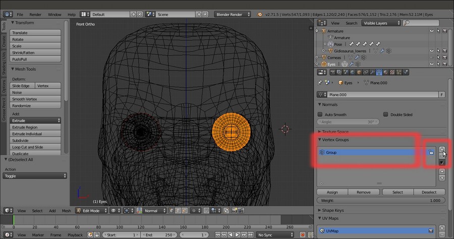
- Go in to Front view and box-select all the vertices of the left eye; then, go to the Vertex Groups subpanel under the Object Data window and click on the + icon to the right to create a new group:

Creating the vertex group for the eyeball
- Ctrl + left-click on the name of the vertex group to rename it as eye.L and then click on the Assign button to assign all the selected vertices to the group with a value of 1.000.
- Deselect everything, select the vertices of the other eye, and create a new vertex group; rename it as eye.R and assign the vertices.

Creating the eye.R vertex group
- Exit Edit Mode (Tab) and go to the Object Modifier window; assign an Armature modifier, move it upwards in the stack, and click on the Object field to select the Armature item as a deforming object.
- Temporarily, unhide the Corneas object in the Outliner and repeat from step 19 to step 23, where we created the eye.L and eye.R vertex groups and assigned the appropriate mesh vertices and the Armature modifier.
The same process must be applied to the skinning of the Armor that, being a single object made of stiff elements, can be easily and ideally divided into different vertex groups; each one is skinned with the full value of 1.000.
- Click on the button to activate the 13th scene layer and show the Armor; select it and enter Edit Mode.
- Select all the vertices of the helm, including the decorations, create the head vertex group in the Armor mesh (remember that the name must be the one of the deforming bones), and click on the Assign button with a weight value of 1.000:

The "head" vertex group for the Armor object
- Repeat the operation with each part of the Armor, so creating, always with a weight of 1.000, the vertex groups: vanbrace.L and vanbrace.R (covering the forearms), greave.L and .R (covering the calves), groinguard (the front hips), kneeguard.L and .R, spaulder.L and .R, and armor_ctrl.
You can use the following screenshot as a guide:

The happy colorful Armor guideline
- Go out of Edit Mode; then, go to the Object Modifier window, assign an Armature modifier to the Armor, move it upwards in the stack, and click on the Object field to select the Armature item as a deforming object.
- Disable the Display modifier in viewport button (the one with the eye icon) for the Subdivision Surface modifier, to speed up the 3D viewport.
For the moment, ignore the Tiers (which have been separated by the Armor object and simplified by deleting several alternate edge-loops, this we'll skin in the next recipe) and save the file.
The Normalize All button normalizes the weights of all the vertex groups so that their sum is not superior to 1.000; because we had assigned a weight of 1.000 to the upper head vertices, the vertices in the other groups that were interfering with the head deformation have been automatically set to 0.000.
The head group, instead, remained the same because it was locked in the Options bottom panel; the Clean button, then, took care of removing all the unwanted vertices in the active group, restricting the inclusion of its vertices only to those with a weight greater than 0.000.
When assigning vertices to a group, the Weight slider under the Vertex Groups subpanel can obviously be set to any value between 0.000 and 1.000, so it's also possible to select a single edge-loop or rows of vertices and assign them at different times to the same vertex groups, but with different weight values. For example, a central edge-loop of vertices with the weight of 1.000 can be surrounded by external edge-loops with weight values of 0.750, 0.500, 0.250, and so on. This is what we have done for the eyelids after the cleaning of the eye sockets area, thanks to the Select, Deselect and Remove buttons. Be aware that the same result can be obtained by painting and/or blurring the weights on the mesh, but we'll see this in the next recipe.
