
1
Finite State Machine
1.1 BASICS OF AUTOMATA
Q. What do you mean by formal language and automata theory (FLAT)?
Ans. Automata have some typical pronounceable symmetry with Automatic. In a computer all processes appear to be done automatically. A given input is being processed in the CPU and an output is generated. We are not concerned about the internal operation in the CPU. We are only concerned about the given input and the received output. However, in reality the input is converted to ‘0' and ‘1' and assigned to the process for which the input was given. It then performs some internal operation in its electronics circuit and generates output in ‘0' and ‘1' format. The output generated in ‘0' and ‘1' format is converted to user understandable format and we get the output. From the discussion it is clear that CPU performs machine operations internally. In Automata we shall learn about how to design such machines.
The name of the subject is formal language and automata theory (FLAT). We have got a basic idea about Automata theory. Now what is Formal language? Let discuss what language is. Language is a communication medium through which two persons communicate. For each nation there is some language to communicate like Hindi, English, Bengali, etc. Similarly for communicating with a computer the user needs some language called programming language. C, C++, Java are some examples of programming language. The characteristics of these types of languages are similar to English language and easily understandable by user. However, computer does not understand English in statements. It only understands binary numbers. Hence, they have a compiler that checks the syntax and acts as a converter from English statement to binary numbers and vice versa. However, to design the compiler some logic is needed. The logic can be designed by use of mathematics. For each language there is a grammar, which is a constructor for any language. Similarly the languages that are used for computer programming rely on grammar to construct them. These rules and grammar and the process to convert such grammar and languages to machine format are the main objectives of this subject.
Q. Why FLAT is sometimes called “Theory of Computer Science”?
Ans. This subject is called “Theory of Computation” because it includes rules for constructing a computer language and converts into machine format; i.e. the theory of computer science. Basically formal language and automata theory and theory of computation are different names for a single subject that covers all the aspects of the theoretical part of Computer Science.
1.2 FINITE STATE MACHINE
Q. Define synchronous and asynchronous circuit.
Ans. Synchronization is usually achieved by some timing device, e.g. clock. A clock produces equally spaced pulses. These pulses are fed into a circuit in such a way that various operations of the circuit take place with the arrival of appropriate clock pulses. Generally the circuits, whose operations are controlled by clock pulses, are called Synchronous circuit.
The operation of asynchronous circuit does not depend on clock pulses. The operations in asynchronous circuit are controlled by a number of completion and initialization signals. Here completion of one operation is the initialization of the execution of next consecutive operation.
Q. Define combinational circuits and sequential circuits. In this respect describe the block diagram of synchronous sequential circuit.
Ans. The circuits where the output depends only on the present input, i.e. output is the function of only present input are called combinational circuits.
O/P = Func.(Present I/P).
The circuits where the output depends on the external input and the stored information at that time, i.e., output is the function of external input and present stored information are called sequential circuits.
O/P = Func.(External I/P and present stored information).
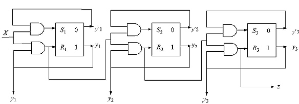
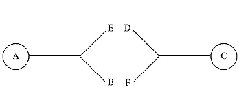
Block diagram
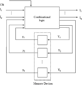
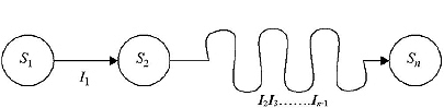
A synchronous sequential machine has finite number of inputs. If a machine has n number of input variables, the input set consists of 2n distinct inputs called input alphabet I.
In the diagram the input alphabet is I = {I1, I2,........, Ip}.
The number of outputs of a synchronous sequential machine is also finite.
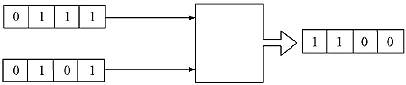
Q. Design a sequential circuit which performs following.
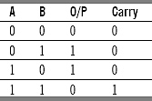
The carry is added with the I/Ps in the next clock pulse.
Ans: Lets take two input strings X1 = 0111 and X2 = 0101.
Here the output at time ti is a function of the inputs X1 and X2 at the time ti and of the carry generated for the input at ti-1
O/P = func.( I/P at ti, and carry generated for the input at ti-1 ),
therefore, this is a sequential circuit.
The table above illustrates the two types of cases arisen. These are:
i. Producing carry ‘0'
ii. Producing carry ‘1'
We have to consider this as the O/P depends of the carry also.
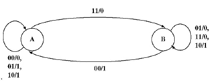
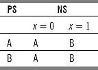
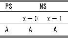
Lets consider the cases as two states A for (i) and B for (ii). A table is constructed for the inputs X1 and X2. This is called state table.
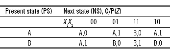
This tabular form can be represented more clearly by a graphical notation. This is called state graph or state diagram
For designing a circuit we need only ‘0’ and ‘1’ i.e., boolean values. Hence the states A and B must be assigned boolean numbers. As there are only two states A and B so only one digit boolean value is sufficient. Lets assign A as ‘0’ and B as ‘1’.
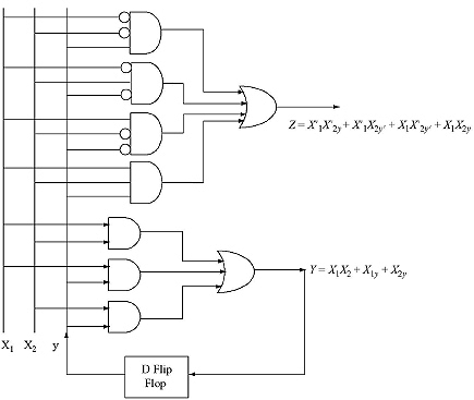
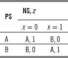
By assigning these boolean values to A and B the modified table become.
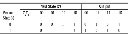
Where the function for next state Y= X1X2 + X1y + X2y, and
the function for output Z= X′1yX′2y + X′1X2y′ + X1X′2y′ + X1X2y
= X1 ![]() X2
X2 ![]() y.
y.
A digital circuit can easily be designed using the above functions. This is the circuit for full binary adder.
Q. Design a full binary substractor.
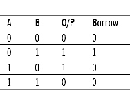
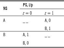
Ans. The truth table for a substractor is as follows:
Lets assign two input strings X1=1010 and X2=0111.
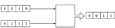
Here the output at time ti is a function of the inputs X1 and X2 at the time ti and the borrow generated for the input at ti-1 .
O/P=func.( I/P at ti and carry generated for the input at ti-1 ).
Therefore, this is a sequential circuit.
In the above table, two types of cases are arisen. These are:
i. Producing Borrow ‘0’
ii. Producing Borrow ‘1’
We have to consider the above as the O/P depends on the borrow too.
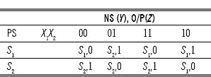
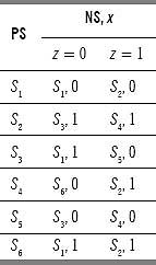
Lets consider the cases as two states S1 for (i) and S2 for (ii). The state table for the binary substractor is constructed for the inputs X1 and X2:
The state graph for binary substractor:
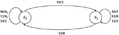
State assignments:
For designing a digital circuit, S1 and S2 are converted into some digital numbers. Since there are only two states, a 1 bit digital number which can produce two types of digital values - 0 or 1; is sufficient to represent S1 and S2.
Lets assign S1 to 0 and S2 to 1.
The modified state table is as follows:
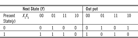
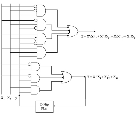
Where the function for next state Y = X1′X2 + X1′y + X2y, and
The function for output Z = X′1X′2y + X′1X2y′ + X1X′2y′ + X1X2y.
The digital circuit designed from the above functions is:
Sequence Detector
Q. Design a two input two output sequence detector which generates an output ‘1' every time the sequence 1001 is detected. And for all other cases output ‘0' is generated. Overlapping sequences are also counted.
Ans. Before designing this circuit some clarifications regarding sequence detector is needed. Lets assign the input string as 1001001.
We have to design the circuit in such a way that it will take one input at a time. The input can be either ‘0’ or ‘1’ (two types of input). The output will be also two types, either ‘0’ or ‘1’. The circuit can store (memorize) the input string up to four clock pulses (ti-3 to ti).
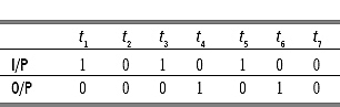
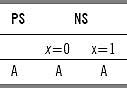
If the input string is placed according to clock pulses, the output is as follows:
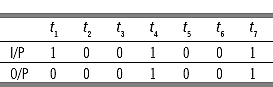
The first input at t1 is 1 and as there is no input from ti-3 to ti the input sequence does not equal to 1001. So the output will be 0. Similar cases occur for the inputs upto t3.
However, at time t4 the input from ti-3 to ti becomes 1001, hence the output ‘1' is produced at time t4. At time t5 and t6 the input string from ti-3 to ti are 0010 and 0100, respectively. Therefore, the output ‘0' is produced. At t7 clock pulse the input string is 1001, hence output ‘1' is produced. As the output ‘1' at t4 is overlapped from t1 to t4 and from t4 to t7, this is called overlapping condition.
![]()
In this case the state diagram is to be drawn first according the following process:
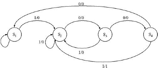
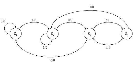
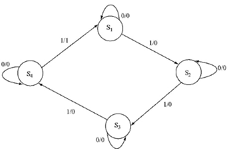
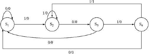
In state S1, input may be either ‘0' or ‘1'. If given input ‘0', there is no chance to get 1001. Hence it loops on S1 with output ‘0'. If the input is ‘1', there is a chance to get 1001 then machine moves to S2 producing output ‘0'.
In S2 again the input may be either ‘0' or ‘1'. If it is ‘1', the input becomes 11. There is no chance to get 1001 by taking previous inputs. But again there is a chance to get 1001 by considering the given input ‘1'. Hence it will be in state S2. (If it goes to S1 then there will be loss of clock pulse, i.e. from S1 by taking input ‘1', again it has to come to S2, i.e., one extra input, i.e. one clock pulse is needed and hence the output will not be in right pattern). If the input is ‘0', the input becomes 10 - by considering the previous input and there is chance to get 1001, so it will come to S3.
In S3 if it gets input ‘0', the input becomes 100 by considering the previous input and it has a chance to get 1001, so it can shift to S4. But if it gets ‘0', it has no chance to get 1001 considering the previous input, but there is a chance to get 1001 by considering the given input ‘1'. So it will shift to S2 as we know by getting ‘1' in S1 the machine comes to S2.
In S4 if it gets ‘0', the input will become 1000, but it does not match with 1001. Therefore, it has to start from the beginning i.e., S1. As overlapping condition is accepted, hence from the last ‘1' of 1001 if it gets 001 only, it will give an output ‘1'. Therefore it will go to S2.
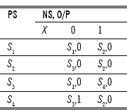
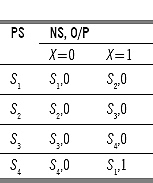
A state table can easily be constructed from the above state diagram.
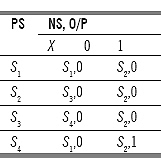
State assignment:
The states must be assigned to some binary numbers to make a digital circuit. This is called state assignment. As the number of states is four, only two digit number is sufficient to represent the four states (22=4).
Lets assign
S1 to 00,
S2 to 01,
S3 to 11,
S4 to 10.
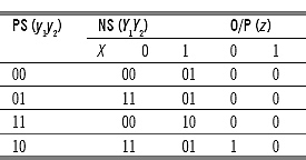
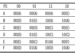
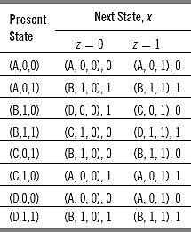
After doing this state assignment the state table becomes
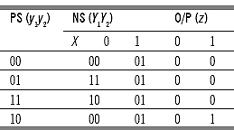
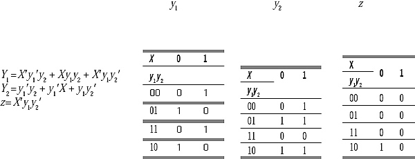
The digital function can easily be derived from this state assignment table:
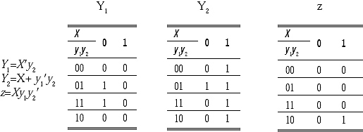
Y1 and Y2 are next states, which are the memory elements. These will be fed back to the input as state y1 and y2 with some delay by D flip flop.
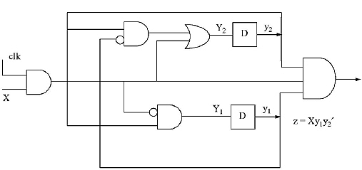
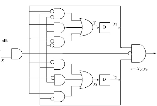
The circuit diagram for this sequence detector will be
Q. Design a two input two output sequence detector which generates an output ‘1' every time the sequence 1010 is detected. And for all other cases output ‘0' is generated. Overlapping sequences are also counted.
Ans. The input string 1010100 is placed according to clock pulses as given below
And the state diagram for the output is as follows:
A state table constructed from the above state diagram:
State assignments:
The states must be assigned to some binary numbers to make a digital circuit. This is called state assignment. As the number of states is 4, only two digit number is sufficient to represent the four states (22=4).
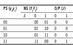
Lets assign
S1 to 00,
S2 to 01,
S3 to 11,
S4 to 10.
The state table after this state assignment:
The digital function can easily be derived from this state assignment table.
The next states, Y1 and Y2, are the memory elements. These will be fed back to the input as state Y1 and Y2 with some delay by D flip flop
Binary Counter
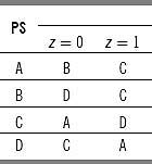
Q. Design a Modulo 3 binary counter
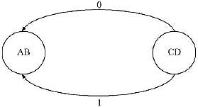
Ans. The Modulo 3 Binary counter can count upto three. Binary representation of three is 11. It can count 00, 01, 10, and 11. There will be an external input x, which will act as a control variable and determine when the count should proceed. After counting three if it has to proceed, then it will come back to 00 again.
The state diagram for Mod 3 binary counter:
The state table for Mod 3 binary counter:
There are four states in the machine. Two bits are sufficient to assign four states into binary number.
Lets assign
S1 to 00,
S2 to 01,
S3 to 10,
S4 to 11.
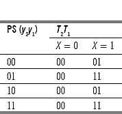
The state table after this state assignment:
Designing By using Flip Flop (T Flip Flop and SR Flip Flop)
The excitation table for T Flip Flop:
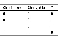
In state assignment, 00 is changed to 00 for input 0. Here y1 is changed from 0 to 0, so T1 will be 0. The y2 is changed from 0 to 1, therefore T1 will be 0. The 00 is changed to 01 for input 1. Here y1 is changed from 0 to 1, therefore T1 will be 1. The y2 is changed from 0 to 0, hence T1 will be 0. The excitation table of the counter using T flip flop by this process:
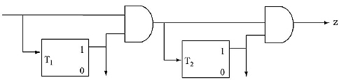
T1 = X,
T2 = Xy1,
z=Xy1y2
The circuit diagram for the above:
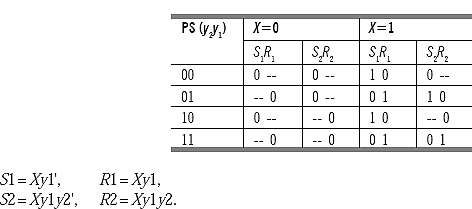
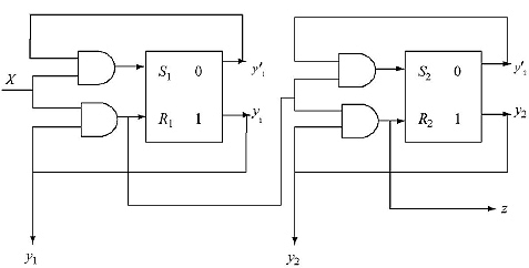
The excitation table for SR Flip Flop:
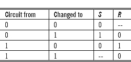
In state assignment, the 00 is changed to 00 for input 0. Here y1 is changed from 0 to 0, hence R1 will be don't care and S1 will be 0. The y2 is changed from 0 to 0, hence R2 will be don't care and S2 will be 0. In state assignment table, 00 is changed to 01 for input 1. Here y1 is changed from 0 to 1, therefore R1 will be 0 and S1 will be 1. The y2 is changed from 0 to 0, hence R2 will be don't care and S2 will be 0. The excitation table of the counter using SR flip flop:
The circuit diagram for the above:
Q. Design a Modulo 8 binary counter.
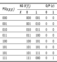
Ans. Modulo 8 Binary counter can count upto eight from 000 to 111. There will be an external input x, which will act as a control variable and determine when the count should proceed. After counting eight if it has to proceed, then it will come back to 000 again.
The state table for Mod 8 binary counter:
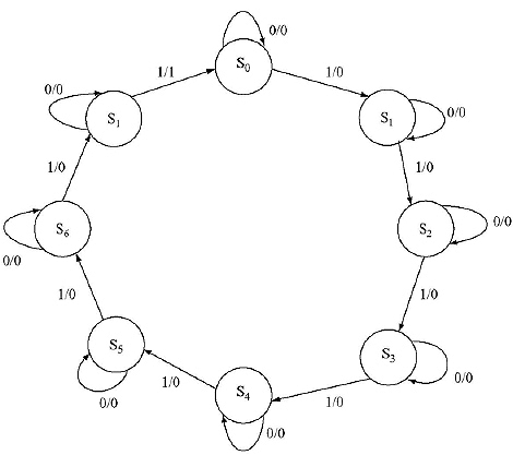
The state table for Mod 8 binary counter:
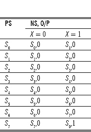
State assignment:
There are eight states in the machine. The three bits are sufficient to assign eight states into binary number (23=8).
Lets assign S1 to 000, S2 to 001, S3 to 010, S4 to 011, S5 to 100, S6 to 101, S7 to 101, S8 to 111.
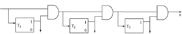
The excitation table of the counter using T flip flop:
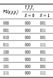
T1 = X , T2 = Xy1, T3 =Xy1y2, z = Xy1y2y3.
The circuit diagram for the above:
The excitation table of the counter using SR flip flop:
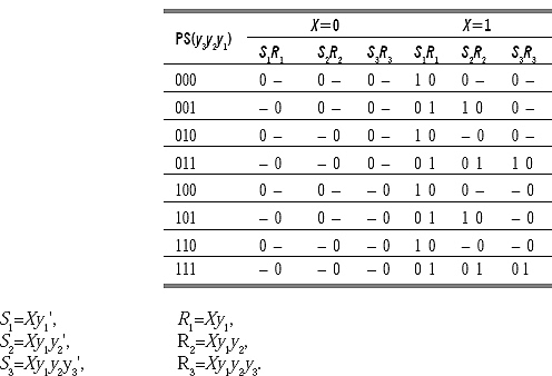
The circuit diagram for the above:
Q. What do you mean by finite state machine?
Ans. Finite state machine can be defined as a type of machine whose past histories can affect its future behavior in a finite number of ways. To clarify, consider for example of binary full adder. Its output depends on the present input and the carry generated from the previous input.
It may have a large number of previous input histories but they can be divided into two types: (i) Input combination that produces carry; (ii) Input combination that produces no carry.
Implying the past histories can affect the future behavior in a finite number of ways (here 2).
Q. What are the capabilities and limitations of finite-state machine?
Ans. Let a finite state machine have n states. Let a long sequence of input be given to the machine. The machine will progress starting from its beginning state to the next states according to the state transitions. However, after some time the input string may be longer than n, the number of states. As there are only n states in the machine, it must come to a state it was previously been in and from this phase if the input remains the same the machine will function in a periodically repeating fashion. From here a conclusion that ‘for a n state machine the output will become periodic after a number of clock pulses less than equal to n can be drawn.
States are memory elements. As for a finite state machine the number of states is finite, so finite number of memory elements are required to design a finite state machine.
Limitations:
(a) No finite state machine can be produced for an infinite sequence.
Lets consider the design of a finite state machine which receives a long sequence of 1. The machine will produce an output 1, when the input string length will be equal to [p(p+1)]/2, where p=1,2,3,...... and 0 for all other cases.
Therefore for p = 1, [p(p + 1)]/2 = 1. In first place there will be o/p 1.
For p = 2, [p(p + 1)]/2 = 3. In third place there will be o/p 1.
For p = 3, [p(p + 1)]/2 = 6. In sixth place there will be o/p 1.
For this type of machine the input output form is as follows:
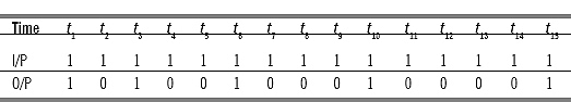
Here the output does not become eventually periodic after a certain number of clock pulses. Hence from this type of sequence no finite state machine can be produced.
(b) No finite state machine can multiply two arbitrary large binary numbers.
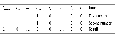
Lets consider multiplying two binary numbers given that are input serially to a finite state machine for multiplication. The inputs are given to the machine with least significant bit (LSB) first then the other bits. Suppose, to multiply 2m ‘ 2m, where m>n (n is the number of states of the Machine), the result will be 22m.
The 2m is represented by one 1 followed by m number of ‘0's (Simlarly 23=1000). Hence the inputs are given to the machine from t1 to tm + 1 time. Throughout the time the machine produces ‘0'. At tm + 2 times the input stops and the machine produce output 0 followed by 1 from tm + 2 to t2m time.
In the time period tm + 1 to t2m, no input is given to the machine, but the machine produces outputs. As m > n, according to the definition of Finite State machine the output must be periodic and the period must be < m. As we are not getting any repeating output sequence, therefore Binary Multiplication of two arbitrary large binary numbers is not possible to design by using finite state machine.
1.3 STATE EQUIVALENCE AND MINIMIZATION OF MACHINE
Q. What do you mean by state equivalence and state distinguishable? Give an example to clarify this.
Ans. Two states Si and Sj of machine M are said to be equivalent if they produce same output sequences for all input string applied to the machine M, considering Si and Sj as initial states.
Two states Si and Sj of machine M are said to be distinguishable if there exists a minimum length input sequence which when applied to the machine M, considering Si and Sj as the initial states, produce different output sequence. (Input string is always applied on initial state)
The sequence that distinguishes those two states is called distinguishing sequence for the pair Si and Sj.
If two states Si and Sj are distinguished for the input string of length k, then Si and Sj are called k distinguishable. The k is the minimum number of the length of the string for which the states produce different output. If two states are k distinguishable then they are (k-1) equivalent for k=k to 1.
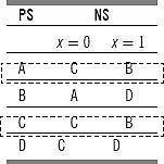
The table given below elucidates the concept
Consider the previous example.
The states A and C give same output (here 0) for the input string of length 1 (Either 0 or 1). Hence A and C are 1 Equivalent.
States A and B give different output for input string of length 1 (For input string length 0, means for no input - outputs are same; but for length 1, in case of input 1 they produce different outputs). Therefore, A and B are 1 distinguishable.
Let check for string length 2. String length 2 means it gives four types of combinations 00, 01, 11 and 10.
The A and E are 2 distinguishable, since they produce different output for 11. Distinguishing sequence for A and E is 11.
Q. Define equivalent partition. Prove that equivalent partition is unique.
Ans. Equivalent partition of a machine M can be defined as a set of maximum number subsets of states where states which reside in same subset are equivalent for any input given to the states. The states which reside in different subsets are distinguishable for some input.
Proof:
Suppose for a machine M there exist two equivalent partitions P1 and P2, where P1 ≠ P2. As P1 ≠ P2, there must exist atleast two states Si and Sj, which are in the same block of one partition (Let P1) and different blocks in other partition(Let P2). As they are in different blocks in P2, there must exist an input sequence which distinguishes Si and Sj. Hence they cannot be in the same block of P1. Therefore, our assumption is wrong. For a single machine here cannot exist two equivalent partitions.
Hence, from here we can conclude that Equivalent partition is unique, i.e. P1 ≡ P2.
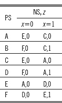
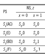
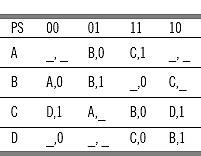
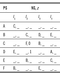
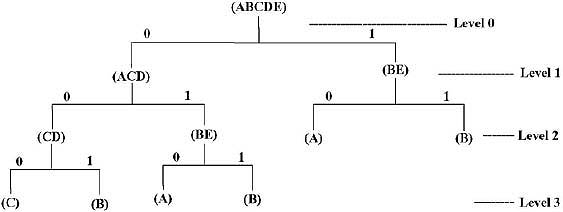
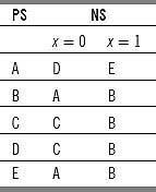
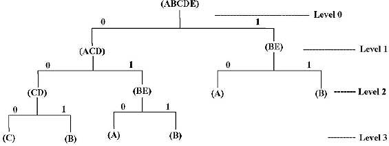
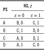
Q. Find the equivalent partition for the machine given below. From here minimize the above machine.
Ans. For string length 0 (i.e. for no input) there is no output, Hence all the states are equivalent.
P0 = (ABCDEF).
Consider for string length 1 (i.e. two inputs 0 or 1). For 0, for all states output is 0. For 1 we get different output for (ACE) and (BDF). States A and B are 1 distinguishable. The A and C are 1 equivalent.
Therefore,
P1=[(ACE) (BDF)].
Consider for string length 2 (i.e. four types of input 00, 01, 11, and 10)
For A and C, outputs are same for 00, 01, 11, and 10. However, E has different output for 11. For B, D, and F outputs are same for all inputs.
P2 = [(AC)(E)(BDF)].
Consider for string length 3 [i.e. eight types of input combinations]. Hence it will be difficult to find output sequences and the equivalent partitions, as the length of input string increases.
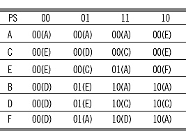
It will be easier to check for the next states.
We know P1 = [(ACE) (BDF)].
Lets rename (ACE) as set S1 and (BDF) as set S2.
For ACE with input 0, the next states are (EEA). Both A and E belong to set S1. For input 1, the next states are (CAD). Here A and C belong to set S1, but D belongs to set S2. Therefore, the set (ACE) will be divided as (AC) and (E) for input string length 2.
For (BDF) with input 0, the next states are (FFD). Both F and D belong to same set S2. For input 1, the next states are (CAE). All of these belong to same set S1. So (BDF) cannot be divided for input string length 2.
The partition of states becomes:
P2=(AC)(E)(BDF) (Same result obtained with considering output).
Lets check for input string length 3.
For (AC) with input 0, the next states are (EE). Both the next states belong to single set. For input 1, the next states are (AC). Both the next states belong to single set. So (AC) cannot be divided for input string length 3.
(E) is a set of single state. So (E) cannot be divided.
For (BDF) with input 0, the next states are (FFD). All of them belong to single set. With input 1, the next states are (CAE). The C and A belong to one set in P2 and E belongs to another set in P2. Hence (BDF) will be divided as (BD) and (F) for input string length 3.
The partition of states becomes:
P3 = (AC)(E)(BD)(F).
Lets check for input string length 4.
For (AC) with input 0, the next states are (EE), belong to single set. For input 1, the next states are (AC), belong to single set. Hence (AC) cannot be divided for input string length 4.
The (E) is a set of single state. Hence (E) cannot be divided.
For (BD) with input 0 and 1, the next states are (FF) and (AC), respectively. (FF) belong to a single set and (AC) also belong to a single set. Hence (BD) cannot be divided. As (F) is a single state, it cannot be divided.
The partition of states becomes
P4 = (AC)(E)(BD)(F).
As P3 and P4 consist of same partitions, P3 = (AC)(E)(BD)(F) is the equivalent partition for the machine M.
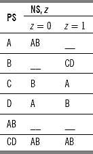
Minimization:
We know that equivalent partition is unique. So P3 = (AC)(E)(BD)(F) is the unique combination. Here each single set represents one state of the minimized machine.
Lets rename these partitions for simplification.
Rename (AC) as S1, (E) as S2, (BD) as S3, and (F) as S4.
The AC with input 0, goes to (EE) with output 0, hence there will be a transaction from S1 to S2 with output 0. E with input 0, goes to A producing output 0. A belongs to set S1 in the minimized machine, Hence there will be a transaction from S2 to S1 with output 0. By this process, the whole table of the minimized machine is constructed.
The minimized machine is as follows:
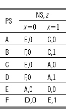
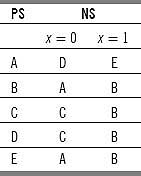
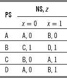
Q. Find the equivalent partition for the machine given below. From here minimize the above machine.
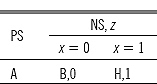
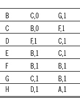
Ans. For string length 0 (i.e. for no input) there is no output, hence all the states are equivalent. It is called 0-equivalent. Expressed as
P0 = (ABCDEFGH).
For string length 1, there are two types of inputs — 0 and 1. The states A, B, and C give output 0 for input 0 and states D, E, F, G, and H give output 1 for input 0. All the states give output 1 for input 1.
Therefore, the states in the set P0 is divided into (ABC) and (D, E, F, G, and H). Written as
Pl = [(ABC) (DEFGH)].
Here A and F are 1 distinguishable because they produce different outputs for input string length 1. For input string length 2, check the distinguishability by next state combination. The states A, B, and C for input 0 produce next states B, C, and B, respectively, and produce next states H, G, and F for input 1. BCB belong to same set, and HGF also belong to same set. Hence ABC cannot be partitioned for input string length 2.
The states DEFGH for input 0, produce next states F, B, B, C, and D, respectively, and produce next states C, C, B, B, and A for input 1. The B, B, and C belong to same set but F and D belong to different sets. Hence the set (DEFGH) is portioned into (DH) and (EFG). The new partition becomes
P2 = {(ABC)[(DH)(EFG)]}.
The states D and G are 2 distinguishable, because they produce different outputs for input string length 2.
The states A, B, and C for input 0 produce next states B,C, and B respectively and produce next states H, G, F for input 1. BCB belong to same set, but H and G, F belong to different set. Hence the set (ABC) is partitioned into (A) and (BC).
The states B and H produce next states C and D, respectively for input 0 and produce next states G and A for input 1. C and D belong to different sets hence the set (BH) is divided to (B) and (H).
The states E, F, and G produce next states B, B and C for input 0 and next states C, B, and B for input 1. Both B and C belong to same set, so the set (EFG) cannot be partitioned.
The new partition becomes
P3 = {[(A)(BC)]{[(D) (H)] (EFG)}}.
Here A and B are 3 distinguishable, because they produce different outputs for input string length 3.
By this process we will get P4 also as
P4 = {[(A)(BC)] {[(D)(H)] (EFG)}}.
As P3 and P4 consist of same partitions, therefore P3={[(A)(BC)]{[(D)(H)](EFG)}} is the equivalent partition for the machine M.
We know that equivalent partition is unique. Therefore P3 = {[(A)(BC)]{[(D)(H)] (EFG)}} is the unique combination. Here each single set represents one state of the minimized machine.
Lets rename these partitions for simplification.
Rename (A) as S1, (BC) as S2, (D) as S3, (H) as S4 and (EFG) as S5.
State (A) with input 0 goes to (B), Hence there will be transaction from S1 to S2 with input 0. The (A) with input 1 goes to (H), hence there will be transaction from S1 to S4 with input 1. The (BC) with input 0 goes to (BC) for input 0. There will be a transaction from S2 to S2 for input 0. State (BC) with input 1 goes to (FG). There will be transaction from S2 to S5 for input 1.
By this process the whole table of the minimized machine is constructed.
The minimized machine becomes
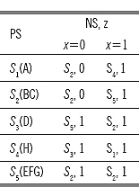
1.4 INCOMPLETELY SPECIFIED MACHINE AND MINIMAL MACHINE
Q. Define incompletely specified machine? How an incompletely specified machine can be simplified? Simplify the following incompletely specified machine.
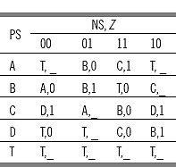
Ans. In real life, for all states for all inputs, the next state or outputs or both are not mentioned. For such types of machines, where for all states for all inputs the next state, or output or both are not mentioned, those types of machines are called incompletely specified machine.
In the previous machine for state A for 00 input no next state and outputs are specified. Hence the previous machine is an example of incompletely specified machine.
An incompletely specified machine can be simplified by the following steps:
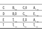
(a) If next state is not mentioned for a state, for a given input, put a temporary state T in that place.
(b) If output is not mentioned, make it blank.
(c) If next state and output are not mentioned, put a temporary state T in next state place and nothing in output place.
(d) Add the temporary state T in the present state column, putting T as next state and no output for all inputs.
By following the previous steps, the simplification of the previous incompletely specified machine is as follows:
Q. Simplify the following incompletely specified machine.
Ans. Put a temporary state T in the next state place, where next states are not specified. If the output is not mentioned, need to put any output.
As a temporary state T is considered, so T is put in the present state column with next states T for all inputs with no output.
The simplified machine becomes
Q. Define Minimal machine. What is the difference with it with minimum machine? Give an example.
Ans. Minimal machine is the minimum of the machines obtained by minimizing an incompletely specified machine.
In an incompletely specified machine, for all states and for all inputs, the next state, or output or both are not mentioned. At the time of minimizing the incompletely specified machine different persons can take the not mentioned next states or outputs according to their choice. Therefore there is a great possibility to get different equivalent partitions for a single machine. But we know equivalent partition is unique for a given machine. It is not possible to find a unique minimized machine for a given incompletely specified machine most of the times. Therefore our aim must be to find a reduced machine which not only covers the original machine but also has a minimal (least of the minimum) number of states. This type of machine is called minimal machine, i.e. it is the minimum of the machines obtained by minimizing an incompletely specified machine.
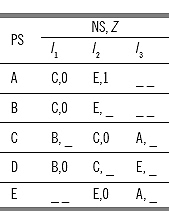
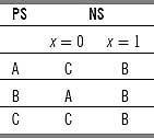
Example: Lets consider the following incompletely specified machine:
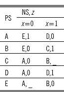
In this machine C with input 1 output is not specified and same for E with input 0. There are two types of outputs occur in the machine. Hence the unspecified outputs can be any of the followings: (a) (B, 0 A, 0); (b) (B, 0 A, 1); (c) (B, 1 A, 1); (d) (B, 1 A, 0).
For (a) the machine and its equivalent partition is
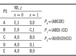
For (b) the machine and its equivalent partition is
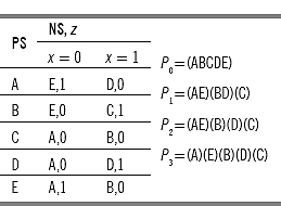
For (c) the machine and its equivalent partition is
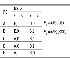
For (d) the machine and its equivalent partition is
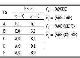
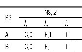
In cases (b) and (d), the number of equivalent partitions are 5, equals to the number of states of the machine, i.e. machine constructed from the equivalent partitioned obtained in cases (b) and (d) and the original machines for cases (b) and (d) are the same.
1.5 MERGER GRAPH AND COMPATIBILITY GRAPH
Q. What is Merger graph?
Ans. Merger graph of a machine M of n states is an undirected graph defined as follows.
1. Merger graph consists of n number of vertices, where n is the number of states of the machine. That is in other words each states of the machine represent one vertex.
2. There is an undirected arc between a pair of vertices (states) if the outputs do not conflict for those pair of states.
(a) The arc will be an uninterrupted arc if the next states of the two states [Vertices] do not conflict.
(b) The arc will be an interrupted arc if the next states of the states [Vertices] conflict. The conflicting next states will be placed in the interrupted portions.
3. There will be no arc between the two vertices if the outputs of the pair of states conflict.
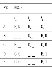
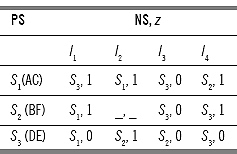
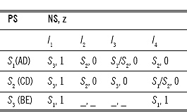
Q. Develop the Merger graph for the following machine.
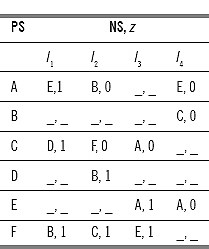
Ans. In the above machine there are six states. Therefore, number of vertices of the Merger Graph is six, namely A, B, C, D, E, and F.
Lets consider two vertices A and B. In the state table for A and B for input I1 outputs are 1 and don't care. It is treated as same output (Don't care can be either 0 or 1). Same for I2, I3, and I4 the outputs do not conflict. (If the outputs are don't care, consider it same with the other) Therefore, an undirected arc is drawn between A and B.
For input I4, A produces next state E and B produces next state C. Hence the undirected arc between A and B is an interrupted arc and EC is placed in the interrupted portion.
Consider A and C. The outputs do not conflict for inputs I1, I2, I3, and I4. An undirected arc is drawn between A and C. The next states produced by A and C for input I1 are D and E, i.e. conflicting. For input I2 the next states are B and F – also conflicting. The arc is an interrupted arc and (BF) and (DE) is placed in the interrupted portion.
Consider A and D. For input I2, A and D produce conflicting outputs – 0 for A and 1 for B. So no arc can be drawn between A and D.
Consider A and E. For all the inputs they produce same outputs. An undirected arc is drawn between A and E. The A and E produce next states E and A, respectively, for input I4. Hence the arc is an interrupted arc and (EA) is placed in the interrupted portion.
Consider A and F. The A and F produce conflicting outputs (0 for A, 1 for F) for input I2. Hence no arc can be drawn between A and F.
By this process, an uninterrupted arc is drawn between B and C.
An uninterrupted arc is drawn between B and D.
An interrupted arc is drawn between B and E and AC is placed in the interrupted portion.
An uninterrupted arc is drawn between B and F.
For input I2, C and D produce conflicting outputs. No arc can be drawn between C and D.
For input I3, C and E produce conflicting outputs. No arc can be drawn between C and E.
For input I3, C and F produce conflicting outputs. No arc can be drawn between C and F.
The D and E produce same outputs and same next states for all the inputs. An uninterrupted arc is drawn between D and E.
The D and F produce same outputs for all the inputs but conflicting next states (B and C) for input I2. An interrupted arc is drawn between D and F and BC is placed in the interrupted portion.
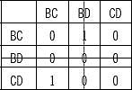
The E and F produce same output for all the inputs but conflicting next states (A and E) for input I3. An interrupted arc is drawn between E and F and AE is placed in the interrupted portion.
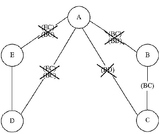
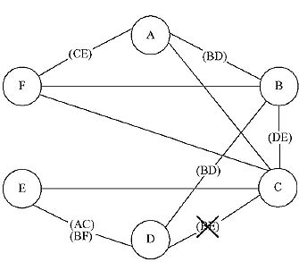
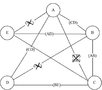
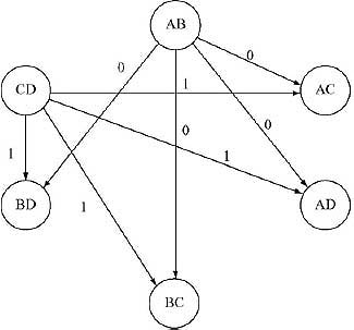
The final Merger graph is
The A and B are connected by an uninterrupted, undirected arc. In the interrupted portion CE is placed. The connection between A and B will be uninterrupted if C and E are connected by uninterrupted arc. But there is no arc between C and E. So there will be no arc between A and B. CE is crossed therefore.
The A and C are connected by uninterrupted undirected arc. In the interrupted portion DE and BF are placed. The A and C will be connected by uninterrupted arc if B, F and D, E are connected.
If either ED or BF is not connected, there will be no arc between A and C. But here ED and BF are connected.
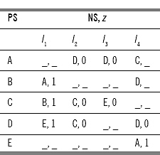
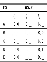
Q. Develop the Merger graph for the following machine.
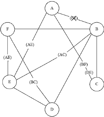
Ans. Number of states of the machine is 5. So number of vertices of the Merger graph is 5. Let name them in the name of the states.
Consider two vertices A and B. The states A and B produce same outputs for all the inputs but different next states for input I2 (conflicting states BD) and for input I3 (conflicting states BC). Hence an interrupted undirected arc is drawn between A and B and (BC), (BD) is placed in the interrupted portion.
Consider A and C. The two states produce same outputs for all the inputs. However, A and C produce conflicting next states (BD) for input I2. Therefore, between A and C an undirected interrupted arc is drawn and (BD) is placed in the interrupted portion.
Consider A and D. The states produce same outputs for all the inputs. But they produce conflicting next states (BC) and (EC) for inputs I1 and I3, respectively. Therefore an undirected interrupted arc is drawn between A and D and (BC)(EC) is placed in the interrupted portion.
Consider A and E. The states produce same outputs for all the inputs. But they produce conflicting next states for input I1 and I3. The conflicting next states are (CE) and (BC). An interrupter arc is drawn between A and E and (CE)(BC) is placed in the interrupted portion.
Consider B and C. They produce same outputs for all the inputs but conflicting next state pair (BC) for input I3. Hence an interrupted arc is drawn between B and C placing (BC) in the interrupted portion.
Consider B and D. No arc is drawn between B and D as they produce different outputs for input I3.
Consider B and E. No arc is drawn between B and E as they produce different outputs for input I3.
Consider C and D. These states produce different outputs for input I3. Therefore no arc is drawn between C and D.
Consider C and E. These states produce different outputs for input I3. Therefore no arc is drawn between C and E.
Consider D and E. They produce same outputs and same next state combination for all the inputs. Therefore an uninterrupted arc is drawn between D and E.
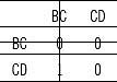
The Merger graph for the above machine:
Between C and E there is no arc. Hence the combinations (EC)(BC), placed between A,D and A,E is crossed off. Now there is no connection between A and E, and A and D. There is no arc between B and D. Hence the next state combination (BC)(BD) and (BD),placed between A,B and A,C, respectively is crossed off.
Q. Define compatible pair and implied pair. What do you mean by a compatibility graph?
Ans.
Compatible Pair: Two states say Si and Sj are said to be compatible, if both of them give same output strings for all input strings applied to the machine separately, considering Si and Sj as the initial states.
(In the sense of Merger Graph, two states are said to be compatible if there exists an uninterrupted arc between the two states.)
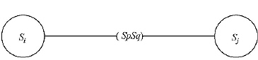
Implied Pair: Two states Si and Sj are said to be implied on Sp and Sq, if and only if (Sp, Sq) is compatible then only (Si, Sj) is compatible. (Sp, Sq) is said to be the implied pair of (Si, Sj).
Compatibility Graph: Compatibility graph is a directed graph constructed as follows:
(1) Number of vertices of the compatibility graph corresponds to the number of compatible pairs obtained from the machine.
(2) A directed arc is drawn between two compatible pairs (vertices) say from (Si, Sj) to (Sp, Sq) [Where (Si, Sj) ≠ (Sp, Sq)], if (Sp, Sq) is the implied pair for Si, Sj).
Q. Define closed compatibles and closed covering. How to find a minimal machine from a given compatibility graph of a machine?
Ans. A Subgraph of a compatibility graph is called closed, if for every vertex in the subgraph, all outgoing arcs and the terminal vertices of the arcs also belong to the subgraph. The pair of states belongs to the subgraph as terminal vertices are called closed compatible. If a subgraph is closed, and if every state of the machine is covered by atleast one vertex of the subgraph of a compatibility graph, then the subgraph forms a closed covering of the machine.
To find a minimal machine we need to find the subgraphs that closed cover the machine. Then we need to find the subgraph that contains less number of vertices and, which can generate a simpler machine. The states of the minimal machine are the vertices of the subgraph. From these states the transition functions are constructed. By this process a minimal machine of the given machine is constructed. [There is no easy method to find minimal closed covering. It will be choose manually]
Q. Draw a compatible graph for the following machine. Hence find the minimal machine.
Ans: To find the Compatible pairs we need to construct the Merger graph of the machine first. The Merger graph of the machine:
The pair of states which are connected by undirected arcs (Not Crossed in the interrupted portion) are compatible pairs. The compatible pairs of the given machine are (AB), (AC), (AF), (BC), (BD), (BF), (CE), (CF), and (DE). Therefore in the compatibility graph there are nine vertices.
In the given machine,
The (BD) is implied pair for (AB). Hence a directed arc is drawn from (AB) to (BD).
The (CE) is implied pair for (AF). Hence a directed arc is drawn from (AF) to (CE).
The (DE) is implied pair for (BC). Hence a directed arc is drawn from (BC) to (DE).
The (BD) is implied pair for (BD). As (Si, Sj)≠ (Sp, Sq) no arc is drawn from (BD) to (BD)
The (AC) and (BF) are implied pair for (DE). The two directed arcs are drawn from (DE) to (AC) and (BF).
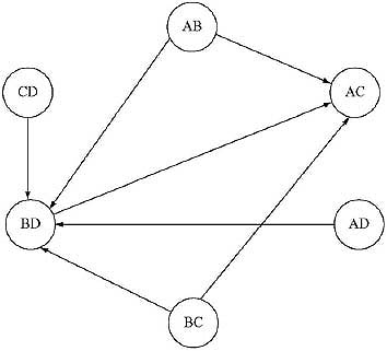
The compatibility graph for the given machine:
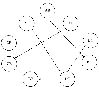
The subgraph (AC), (DE), (BF) or (AB), (BD), (AF), (CE) or (AF), (CE), (BC), and (DE) are closed subgraphs of the compatibility graph and forms a closed cover of the machine (Here every state of the machine is covered by atleast one vertex of the subgraph). Among them, the subgraph (AC), (DE), and (BF) contains less number of vertices. In the minimal machine the states are (AC), (BF), and (DE). Let rename them as S1, S2, and S3, respectively. The minimal machine becomes
Q. Draw a compatible graph for the following machine. Hence find the minimal machine.
Ans: To find the compatible pairs of a machine, we need to construct the Merger the graph first. According to the rules of the construction of Merger Graph the following graph is constructed.
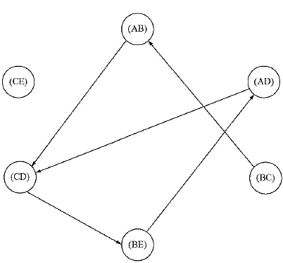
The pair of states which are connected by undirected arcs (Not crossed in the interrupted portion) are compatible pairs. The compatible pairs of the given machine are (AB), (AD), (BC), (BE), (CD) and (CE). Therefore in the compatibility graph of the above machine there are nine vertices.
The (CD) is implied pair for (AB). A directed arc is drawn from (AB) to (CD).
The (CD) is implied pair for (AD). A directed arc is drawn from (AD) to (CD).
The (AB) is implied pair for (BC). A directed arc is drawn from (BC) to (AB).
The (AD) is implied pair for (BE). A directed arc is drawn from (BE) to (AD).
The (BE) is implied pair for (CD). A directed arc is drawn from (CD) to (BE).
The compatibility graph is
Minimal Machine:
In the above compatibility graph, the subgraph (AD), (CD), and (BE) forms a closed covering of the given machine. The states of the minimal machine are (AD), (CD) and (BE). Let rename them as S1, S2, and S3, respectively. The minimal machine of the above machine:
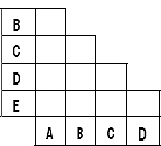
Q. What is Merger table? Why Merger table is used? How is a Merger table is constructed?
Ans. Merger table is a substitute application of Merger graph. From a Merger graph we can get the compatible pairs and implied pairs.
If number of states of a machine increases, number of combination pair increases. For a machine of n states, number of two state combinations are nC2 i.e. n(n-1)/2. If n=(n-1), number of combinations are (n-1)(n-2)/2. Number of combination increases to (n-1) if number of states increases from (n-1) to n. It is difficult to connect two states by arcs in a merger graph, if number of states increase. Hence a Merger table is an easier process to find compatible pairs and implied pairs.
Process of construction:
A Merger table can be constructed as follows:
1. Make a table of (n-1) x (n-1) where left-hand-side is labeled by second state to nth state and right-hand-side is labeled by first state to (n-1)th state.
2. Each box represents a pair of states combination.
3. Put a cross in the box if the output conflict for the pair of states.
4. Put a right sign in the box if the outputs as well as next states do not conflict for the pair of states.
5. If the outputs do not conflict but the next states conflict for the pair of states, put the conflicting next states in the box.
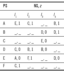
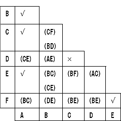
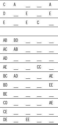
Q. Construct Merger table of the following machine and find the compatible pairs.
Ans: Make a table like the following
Consider the state combination (AB). Here outputs do not conflict but the next states for I2 and I3 conflict. Hence conflicting next state combination, (BD) and (BC) are placed in the box labeled (AB).
Consider the state combination (AC). Here outputs do not conflict but the next states for I2 conflict. Hence conflicting next state combination, (BD) is placed in the box labeled (AC).
Consider the state combination (AD). Outputs do not conflict, but the next states for I1 and I3 conflict. Conflicting next state combinations (CE) and (BC) are placed in the box labeled (AD).
Consider state combination (AE). The outputs for the states do not conflict, but the next states for input I1 and I3 conflict. The (CE) and (BC) are placed in the box labeled (AE).
Consider state combination (BD). Here outputs for input I3 conflict. There will be a ![]() (cross) in the box labeled (BD).
(cross) in the box labeled (BD).
Consider state combination (DE). Here both the outputs and next state combination are same for all the inputs. Hence a ![]() (tick) is placed in the box labeled (DE).
(tick) is placed in the box labeled (DE).
By this process the Constructed Merger Table is:
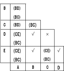
The boxes which are not crossed are compatible pairs. Hence, the compatible pairs are (AB), (AC), (AD), (AE), (BC), (BD), (BE), (CD), and (DE).
Q. Construct Merger table of the following machine and find the compatible pairs.
Ans: For the states AB, for all the inputs, next states and output do not conflict. Hence a ![]() (tick) is placed in the box labeled AB. For states AC, next states and outputs do not conflict for all the inputs. Hence a
(tick) is placed in the box labeled AB. For states AC, next states and outputs do not conflict for all the inputs. Hence a ![]() (tick) is placed in the box labeled AC. For states AD, the outputs do not conflict, but the next states for input I1 conflict. So the conflicting next state pair (CE) is placed in the box labeled AD.
(tick) is placed in the box labeled AC. For states AD, the outputs do not conflict, but the next states for input I1 conflict. So the conflicting next state pair (CE) is placed in the box labeled AD.
In the box labeled (AE) a ![]() (tick) is placed.
(tick) is placed.
In the box (AF), conflicting next state pair (BC) is placed.
In the box (BC), conflicting next state pair (CF) and (BD) is placed.
In the box (BD), conflicting next state pair (AE) is placed.
In the box (BE), conflicting next state pair (BC) and (CE) is placed.
In the box (BF), conflicting next state pair (DE) is placed.
The outputs for I2 for state (CD), conflict. Hence a ‘ (cross) is placed in the box (CD).
In the box (CE), conflicting next state pair (BF) is placed.
In the box (CF), conflicting next state pair (BE) is placed.
By this process the constructed Merger table
The compatible pairs are (AB), (AC), (AD), (AE), (AF), (BC), (BD), (DE), (DF), (CE), (CF), (DE), (DF), and (EF).
Q. Construct Merger Table of the following machine and find the compatible pairs.
Ans. The Merger Table for the above machine is:
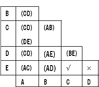
Here (DE) is crossed, hence (AC) will be crossed. As (AC) is crossed, (AE) will be crossed. As (AE) is crossed, (BD) will be crossed. The final Merger graph:
The compatible pairs of the given machine are (AB), (AD), (BC), (BE), (CD) and (CE).
1.6 FINITE MEMORY AND DEFINITE MEMORY MACHINE
Q. Define finite memory machine. What are the processes of testing whether a machine is finite or not?
Ans.
Finite memory machine:
A finite state machine M is called finite memory machine of order μ if μ is the least integer so that the present state of the machine M can be obtained uniquely from the knowledge of last μ number of inputs and the corresponding μ number of outputs. There are two methods to find a machine is finite or not:
1. Testing table and testing Graph for finite memory
2. Vanishing connection Matrix.
1. Testing table and testing Graph for finite memory method
The testing table for finite memory is divided into two halves. Upper half contains single state input-output combination. If in a machine there are two types of inputs and two types of outputs let 0 and 1, the input-output combinations are 0/0, 0/1, 1/0, and 1/1. Here 0/0 means 0 input and 0 outputs, i.e. for the cases we are getting output 0 for input 0, 0/1 means 0 input and 1 output, i.e. for the cases we are getting output 1 for input 0. Lower half of the table contains all combination of present states taking two into combination. For four present states (Let A, B, C, and D) there are 4C2 means 6 combinations. AB, AC, AD, BC, BD, and CD. Table is constructed according to the machine given. Pair of present state combination is called uncertainty pair. And its successor is called implied pair.
In the testing graph for finite memory
1. Number of nodes will be number of present states combination taking two into account.
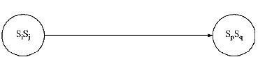
2. There will be an directed arc with label of input output combination, from SiSj (i ≠ j) to SpSq (p ≠ q) if SpSq is the implied pair of SiSj.
If the testing graph is of loop free, the machine is of finite memory. The order of finiteness is the length of the longest path in the testing graph (l) + 1, i.e. μ=l+1.
2. Vanishing connection matrix method
If the number of states increases then it becomes difficult to find the longest path in the testing graph for finite memory. There is an easy method to determine whether a machine is finite or not, and if finite, to find its order of finiteness. The process is called vanishing connection matrix method.
Constructing method of connection matrix.
1. Number of Rows will be equal to number of columns (p X p matrix).
2. The rows and columns will be labeled with the pair of present state combinations. The labels associated with corresponding rows and columns will be identical.
3. In the matrix (i, j)th entry will be 1 if there is an entry in (SaSb) and (SpSq) combination in the corresponding testing table. Otherwise the entry will be 0.
Vanishing of connection matrix
1. Delete all rows having 0s in all positions and delete the corresponding columns also.
2. Repeat this step until one of the following steps achieved:
(i) No row left with having 0's in all positions.
(ii) The matrix vanish that means no rows and no columns left.
If the condition 2(i) arrives the machine is not of finite memory.
If the condition 2(ii) arrives the machine is of finite memory and the number of steps requires to vanish the matrix is the order of finiteness of the machine.
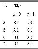
Q. Test whether the following machine is of finite memory or not by using testing table-testing graph and vanishing matrix method.
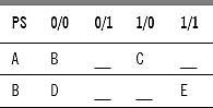
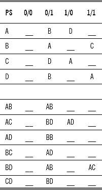
Ans. A table which is divided into two halves is made. The machine has two inputs and two outputs. There are four input-output combinations namely 0/0, 0/1, 1/0, 1/1. The upper half of the machine contains single state input output combination and lower half contain two state input output combinations. There are four states, so six combination pairs are made. The testing table becomes
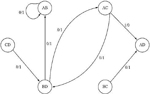
In Testing Table there are six present states combinations. So, in the testing table there are six nodes. There is a directed arc with label of input output combination, from SiSj (i ≠ j) to SpSq (p ≠ q) if SpSq is the implied pair of SpSq. The testing graph for finite memory:
(AB to AA there will be no arc as in AA, both are the repetition of same state).
The longest path in the Testing graph is 5 [CD → BC → BD → AD → AC → AB], so the order of definiteness μ = 5+1 =6.
Vanishing connection matrix method
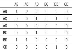
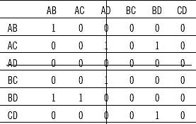
According to the rule of the construction of Connection Matrix a table is constructed with six rows and six columns labeled with the present state combinations. In the testing table, (AB) is the next state combination for (AC) for input 1/1. So an entry 1 is placed in the box labeled (AC)(AB).[i.e.{Label of Row] [Label of Column]} All the other entries are 0.
By this process the following vanishing connection matrix is generated.
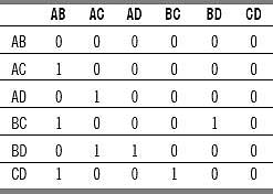
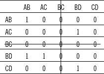
The row labeled AB contains all entry ‘0’. So the row labeled AB and the corresponding column is crossed.
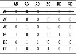
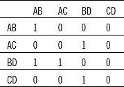
Now the table does not contain the row and column labeled AB. The row labeled AC contains all ‘0'. So the row labeled AC and the corresponding column is crossed.
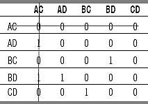
Now the table does not contain the row and column labeled AC. The row labeled AD contains all ‘0'. So the row labeled AD and the corresponding column is crossed.
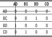
The table does not contain the row and column labeled AD. The row labeled BD contains all ‘0'. So the row labeled BD and the corresponding column is crossed.
The table does not contain the row and column labeled BD. The row labeled BC contains all ‘0'. So the row labeled BC and the corresponding column is crossed.
The table does not contain the row and column labeled BC. The row labeled CD contains all ‘0'. So the row labeled CD and the corresponding column is crossed, means the matrix vanishes.

Number of steps required to vanish the matrix is six. Hence order of finiteness μ=6.
Q. Check whether the following machine is of Finite Memory or not by vanishing Connection Matrix Method.
Ans: To construct the connection matrix we need to first construct the testing table. The testing table
According to the rule of the construction of connection matrix a table is constructed with 10 rows and 10 columns labeled with the present state combinations. In the testing table there is an entry BD for AB for input 0/0. Hence a ‘1’ is placed in AB row BD column entry. All the other entries are ‘0’. By this process the constructed connection matrix:
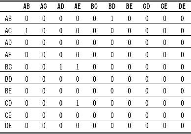
In the matrix the rows labeled AD, AE, BD, BE, CE, and DE contain all 0 entries. These rows with the corresponding columns are crossed off.
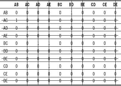
In the Matrix there is no row and columns labeled AC, AD, AE, BD, BE, DE. In the modified matrix all the rows contain ‘0', so all the rows and corresponding columns are crossed.
The matrix vanishes. Number of steps required to vanish the matrix is 2. Hence order of finiteness of the machine μ = 2.
Q. Check whether the following machine is of Finite Memory or not by Testing table -Testing graph and vanishing connection matrix method.
Ans. A table that is divided into two halves is made. The machine has two inputs and two outputs. There are four input-output combinations namely 0/0, 0/1, 1/0, 1/1. The upper half of the machine contains single-state input-output combination and lower half contain two-state input-output combinations. There are four states, so six combination pairs are made. The testing table becomes:
In testing table there are six present states combinations. Hence, in the testing table there are six nodes. There is a directed arc with label of input-output combination, from SiSj (i ≠ j) to SpSq (p ≠ q) if SpSq is the implied pair of SiSj. The testing graph for finite memory:
The testing graph for finite memory contain two loops AB to AB with label 0/1 and AC to BD with label 0/1, BD to AC with label 0/1. As the testing graph is not loop free the machine is not of finite memory.
Test by vanishing connection matrix method:
In the testing table, six present state pairs are formed. Therefore the connection matrix consists of six rows and six columns. The rows and columns are labeled with pair of present state combinations. In the matrix (i,j)th entry will be 1 if there is an entry in (SaSb) (a 1 b) and (SpSq) (p 1 q) combination in the corresponding testing table. Otherwise the entry will be 0. The connection matrix of the above machine is as follows:
In the above matrix the row AD contains all ‘0'. Hence the row labeled AD and the corresponding column vanishes.
In the modified matrix there is no row and column labeled AD. The row labeled BC contains all ‘0'. Therefore, the row labeled BC and the corresponding column vanishes.
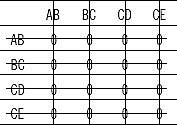
In the modified matrix there is no row and column labeled BC. The modified matrix becomes
The matrix does not contain any row containing all ‘0'. So the matrix does not vanish. Therefore the machine is not of finite memory.
Q. Define definite machine. What are the processes of testing whether a machine is definite or not?
Ans. Definite Machine: A sequential machine M is called definite if there exist a least integer μ, so that the present state of the machine M can be uniquely obtained from the past μ number of inputs to the machine M. Hence μ is called the order of definiteness of the machine.
There are three methods to find a machine is definite or not.
1. Synchronizing tree method
2. Contracted table method
3. Testing table-testing graph for definiteness method.
1. Synchronizing tree method:
For a machine with definite memory only inputs play a role. There is no role of outputs. So, the present state combinations can be divided into two parts for two types of inputs, 0 and 1. Those divided combinations of states can again be divided for input 0 and 1.
If the leaf nodes are of single state, stop constructing the tree. The order of definiteness is the maximum label of the synchronizing tree. Else the machine is not of definite memory.
2. Contracted table method:
(a) Find those present states whose next states are identical.
(b) Represent those present states as single states (Those present states are equivalent).
(c) Obtain the contracted table by replacing only one of the present states from the equivalent state set and modify the table according to it.
(d) Repeat steps from (a) to (c) until new contraction are possible.
By this process if at last a machine with single state is received, then the machine is definite. Its order is the number of steps required to obtain the single state machine. Else the machine is not definite.
3. Testing table-testing graph for definiteness method.
The Testing Table for definiteness is divided into two halves. The upper half contains input and next state combination. Lower half of the table contains all combination of present states taking two into combination. For four present states (Let A, B, C, and D) there are 4C2, i.e. six combinations. AB, AC, AD, BC, BD, and CD.
Table is constructed according to the machine given. For these present state combinations find the next state combinations for input 0 and input 1. Pair of present state combination is called uncertainty pair. And its successor is called implied pair.
In the testing graph for definite memory,
1. Number of nodes will be number of present states combination taking two into account.
2. There will be an directed arc with label of input output combination, from SiSj (i ≠ j) to SpSq (p ≠ q) if SpSq is the implied pair of SiSj.
If the testing graph is loop-free, the machine is of definite memory. The order of definiteness is the length of the longest path in the testing graph (l) + 1, i.e. μ=l+1.
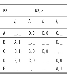
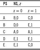
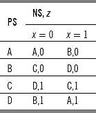
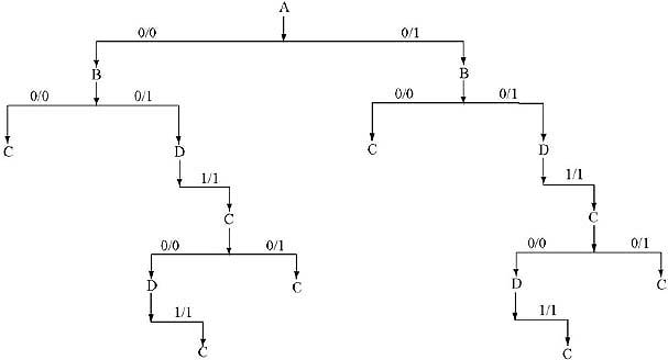
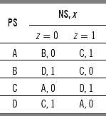
Q. Test whether the following machine is definite or not by any of the method. If definite find the order of definiteness.
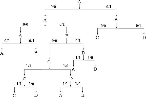
Ans. Synchronizing Tree Method: The present state combination of the machine is (ABCD). It has two types of inputs 0 and 1. The (ABCD) with input 0 produce next state combination (CACC). It can be grouped into two distinct states (AC). The (ABCD) with input 1 produce next state combination (BDBD) which can be grouped into (BD).
In the next level, (AC) with input 0 produces a single next state C. With input 1, (AC) produces single next state B. As C and B are single states, no need to approach further to next level. The state combination (BD) with input 0 produces next state combination (AC). With input 1, state combination (BD) produces single state D. In the next level state combination (AC) produces C and B, respectively for input 0 and 1.
As the leaf nodes are of single state, stop constructing the tree. The order of definiteness is the maximum label of the synchronizing tree. In this case order is 3.
Contracted table method
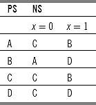
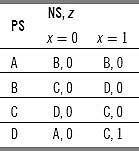
In the previous machine A and C have same next state combination (both cases C and B). Therefore, A and C are equivalent states. Among A and C let take only A, i.e. all the C in the state table are replaced by A. The contracted table is
In the table, B and D produce same next state combination for input 0 and 1. Therefore, B and D are equivalent states. D is replaced by B. The contracted table becomes
The table contains two states A and B with same next states combination for input 0 and 1. So they are equivalent states. B is replaced by A. The contracted table becomes
A machine with single state is received, the machine is definite. Its order is the number of steps required to obtain the single state machine (here 3).
Testing table testing graph method:
A table with two halves is made. The upper half contains input and next state combination. Lower half of the table contains all combination of present states taking two into combination. Here for four present states (Let A, B, C, and D) there are 4C2 means six combinations. AB, AC, AD, BC, BD, and CD. The table:
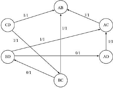
The lower half of the testing table contains six present state combination pairs. The testing graph:
The testing graph is loop-free. So the machine is of definite memory. The longest path of the testing graph is 2 [AB ![]() BD
BD ![]() AC or AD
AC or AD ![]() BD
BD ![]() AC]. So order of definiteness of the machine is 2+1 = 3.
AC]. So order of definiteness of the machine is 2+1 = 3.
Q. Test whether the following machine is definite or not by any of the method (synchronizing tree or contracted table). If definite, find the order of definiteness.
Ans. Synchronizing Tree Method:
The synchronizing tree thus obtained contains leaf nodes of single state. Hence the machine is of definite memory. Number of level of the tree is 3. Therefore, order of definiteness of the machine is 3.
Contracted table method:
States B and E are producing same next state combination for input 0 and 1. Hence they are equivalent. The E is replaced by B, C and D is producing same next state combination, D is replaced by C. The contracted table becomes
State A and C are producing same next state combination for input 0 and 1. Hence A and C are equivalent, C is replaced by A. The contracted table becomes
Both of the states are producing same next state combination, so they are equivalent. B is replaced by A.
The machine becomes a single-state machine. It is of definite memory. Number of steps required to make it a single-state machine is three. Therefore, order of definiteness of the machine is 3.
1.7 INFORMATION LOSSLESS MACHINE AND INVERSE MACHINE
Q. Describe the concept of information losslessness. Define information lossless machine. Justify your definition with an example.
Ans. The main problem of coding and information transmission theory is to determine the conditions for which it is possible to regenerate the input sequence given to a machine from the achieved output sequence.Let information be given to a machine, used for coding device. Input and the output achieved is the coded message and let the initial and final states be known. It this case information losslessness of the machine guarantees that the coded message (output) can always be deciphered.
A machine is called information lossless if its initial state, final state, and output string is sufficient to determine uniquely the input string.
A machine is said to be (information) lossless of order μ (ILF-μ) if the knowledge of the initial state and the first μ output symbols is sufficient to determine uniquely the first input symbol.
Example:
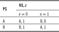
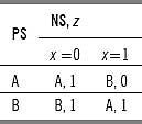
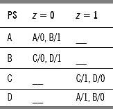
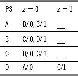
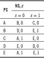
Let take a machine M as follows
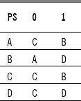
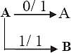
Let the initial state of the machine be A, final state achieved is A, and coded message (output) is 01. We have to find the information given as input. A as a next state is produced for two cases A as a present state for input 0 and B as a present state for input 1. By this process the output successor table is constructed.
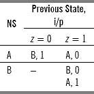
Now we construct the machine according to the output achieved.
Output 01 implies that when reversed it is 10. Initial state is A and final state is A. Hence the diagram will become
![]()
Output 1 with next state A is produced for two cases - Previous state A with input 0 or previous state B with input 1.
Output 0 with next state A is produced for no cases. Output 0 with next state B is produced for two cases - previous state A with input 1 and previous state B with input 0.
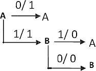
The initial state is A. In the previous case A is produced for input 11. Therefore, the input is 11.
Q. What is lossy machine? Describe with an example. What is the condition for a machine to be a lossy?
Ans: A machine which is not lossless is called lossy.
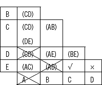
If the testing table obtained from the given machine contains repeated entry of states, the machine is lossy. As an example for the previous machine the testing table is as follows
The testing table contains repeated entry of states in the form of AA. So the machine is lossy.
Q. What do you mean by output compatible pair and its implied pair? Ans.
Ans: Two states Si,Sj of a machine M are said to be output compatible if there exist some state Sp, such that both Si and Sj are its Ok successor or there exists a compatible pair of states Sa, Sb such that SiSj are its Ok successor.
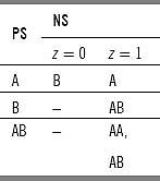
If we construct output successor table for it, the table will be
Let apply input 1 and 0 on states B and A, respectively. The next state will be A for both the cases and the output will be 1 for both the cases. Therefore, we can say A and B are output compatible as there exist a state A such that both A and B are its 1 successor.
Q. What is the process of testing an information lossless machine? How to determine the order of lossnessness?
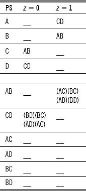
Ans. The process of testing a machine is information lossless or not, is to construct a testing table and testing graph. The testing table is constructed in the following way.
i. The testing table for checking information losslessness is divided into two halves. The upper half contains present states and its output successors.
ii. The lower half of the table is constructed in the following way
(a) Every compatible pair appearing in the output successor table is taken into present state column. The successors of these pairs are constructed from the original table. Here if any compatible pair appears, then that pair is called the implied pair for the compatible pair in the present state column.
(b) That new pair is again taken in the present state column if it is not taken.
(c) The process terminates when all compatible pairs have been taken in the present state column.
The machine is information lossless if and only if its testing table does not contain any compatible pair consisting of repeated entry. From the testing table, testing graph is constructed. The testing graph is constructed in the following way.
(1) Number of vertices of the testing graph is equal to number of output compatible pairs taken in the lower half of the testing table. The labels of the vertices are the compatible pairs in the lower half of the testing table.
(2) A directed arc is drawn from vertex SiSj to vertex SpSq (p1q) if SpSq is implied pair for SiSj.
The machine is information lossless if the testing graph is loop free and its order m = l + 2, where l is the length of the longest path of the testing graph.
Q. Test whether the following machine is information lossless or not. If lossless find its order.
Ans. First step to test whether a machine is lossless or not is to construct a testing table. The testing table is divided into two halves.
Testing graph consists of six vertices.
The testing table does not contain any repeated entry. The machine is lossless machine. The testing graph does not contain any loop. The order of losslessness is μ = 1 + 2 = 3. The length of the longest path of the graph is 1.
Q. Find the input string which is applied on state ‘A' producing output string 00011 and final state ‘B' for the machine given below.
Ans. First we need to prove the machine is information lossless. For this we need to construct a testing table for information lossless.
The testing table does not contain any repeated entry. So the machine is information lossless.
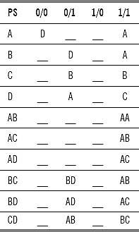
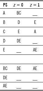
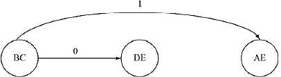
We need to first construct the output successor table
The input string is applied on state A and has produced output 0. From the output successor table it is clear that the next states are A or B. By this process the transition is like the following:
After traversing the total output string by output successor table we have got a state B. Hence, the input string is 01000.
(Input string retrieval is only possible for Information lossless machine. This can be Illustrated In the following example)
Q. Find the input string which is applied on state ‘A' producing output string 00101 and final state ‘C' for the machine given below.
Ans. The machine is not information lossless as in the testing table for information losslessness contains a repeated entry BB for the state ‘A' and output ‘0'. Yet, again try to find the input sequence by constructing the output successor table.
The output successor table for the given machine is
The input string is applied on state A and has produced output 0. From the output successor table it is clear that the next states are B with input 0 or B with input 1. By this process, the following transition is obtained:
We are getting C as final state for two input sequences 01101 and 11101. Hence we cannot uniquely determine the input string. We can conclude that input string retrieval is not possible for information lossy machine.
Q. Test whether the following machine is information lossless or not. If lossless find its order.
Ans. First step to test whether a machine is lossless or not is to construct a testing table. The testing table is divided into two halves.
The testing table does not contain any repeated entry. The machine is information lossless machine. The testing graph for the machine:
The testing graph for information losslessness is loop-free. The order of losslessness is μ=1+2=3. The length of the longest path of the graph is 1.
1.8 INVERSE MACHINE
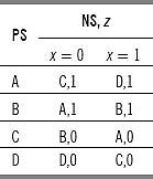
Q. Define inverse machine. What is the necessary condition for constructing an inverse machine from a given machine? Construct an inverse machine of the following machine.
Ans. An inverse machine Mi is a machine which is developed from the given machine M with its output sequence and produces the input sequence given to machine M, after at most a finite delay. A deterministic inverse machine can be constructed if and only if the given machine is lossless. The machine can produce the input sequence applied to the original machine after at most a finite delay if and only if M is lossless of finite order.
Inverse Machine of the given machine
Before constructing the inverse machine we need to test whether the machine is information lossless or not. The testing table for information lossless:
This is information lossless of first order, as here first input symbol can be determined from the knowledge of the initial state and the first output symbol.
As the machine is information lossless, inverse machine for it can be constructed.
The inverse machine is
Q. Define minimal inverse machine. Construct a minimal inverse machine for the machine given below.
Ans. Inverse machine is only possible if the machine is lossless. First we have to check if the machine is lossless or not.
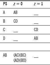
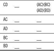
The machine is lossless as the testing table does not contain any entry of repeated states. The testing graph for the information lossless machine:
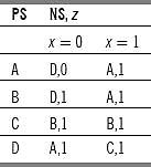
The order of losslessness of the machine is 3. Let us define a set of triple denoted (S(t), z(t + 1), z(t + 2)).
Where S(t) is the initial state of the machine, z(t + 1) is the one of the output symbols that can be produced by single transition from this state, z(t + 2) is another output symbol that can follow this initial state and the first output symbol.
For the given machine the possible triples are
(A, 0, 0) (B, 1, 0) (C, 0, 1) (D, 0, 0)
(A, 0, 1) (B, 1, 1) (C, 1, 0) (D, 1, 1).
[Let take B. The state B has outputs ‘1 ‘ for both input ‘0’ and ‘1 ’. So make a combinations (B,1, ) and (B, 1, ). Next states of B are C and D. C produces outputs ‘0’ and ‘1 ’ and D produces outputs ‘0’ and ‘1 ’. So the triples are (B, 1, 0) and (B, 1, 1)]
The minimal inverse machine is constructed by the following rule.
i. Present states are the triples obtained from the given machine.
ii. The first member is the state to which the machine goes when it is initially in the state that is the first member of the present inverse state, and when it is supplied with the first input symbol.
iii. The second member is the third member of the corresponding present state.
iv. The third member is the present output of the constructing minimal inverse machine.
v. The output of constructing minimal inverse machine is equal to input at (t-2) to the given information lossless machine. (As an example : From B we get D for input 1 and C for input 0. So for the third row the outputs are 1 and 0, respectively)
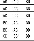
The Minimal inverse machine:
In the previous machine state (A,0,1), (D,1,1) and state (A,0,0), (D,0,0) are equivalent as they produce same next states and same output. To minimize the machine assume
(A, 0, 0) as S1, (A, 0, 1) as S2
(B, 1, 0) as S3 (B, 1, 1) as S4
(C, 0, 1) as S5 (C, 1, 0) as S6
No need to name (D, 0, 0) and (D, 1, 1) as they are equivalent with S1 and S2 respectively.
The minimized machine:
WHAT WE HAVE LEARNED SO FAR
1. Formal language and automata theory and theory of computation are different names for a single subject that covers all the aspects of the theoretical part of Computer Science.
2. The circuits, whose operations are controlled by clock pulses, are called synchronous circuit. The operations in asynchronous circuit are controlled by a number of completion and initialization signals. Here completion of one operation is the initialization of the execution of next consecutive operation.
3. In combinational circuit output depends on present state only.
i.e. O/P = Func.(Present I/P ).
In sequential circuit output is the function of external input and present stored information.
i.e. O/P = Func.(External I/P and Present stored information).
4. Finite state machine can be defined as a type of machine whose past histories can affect its future behavior in a finite number of ways. Finite state machine has finite number of states.
5. No Finite state machine can be designed for an infinite sequence. No finite state machine can multiply two arbitrary large binary numbers.
6. Two states of a machine are called equivalent if they produce same output sequence for an input sequence applied to the states separately considering those two states as initial states.
7. Equivalent partition of a machine M can be defined as a set of maximum number subsets of states where states which reside in same subset are equivalent for any input given to the states.
8. Equivalent partition is unique.
9. The machines where for all states for all inputs, the next state or outputs or both are not mentioned are called incompletely specified machine.
10. Minimal machine is the minimum of the machines obtained by minimizing an incompletely specified machine.
11. Merger graph is an undirected graph where as compatible graph is a directed graph.
12. Merger table is a substitution of Merger graph.
13. A finite state machine M is called finite memory machine of order μ if μ is the least integer so that the present state of the machine M can be obtained uniquely from the knowledge of last μ number of inputs and the corresponding μ number of outputs.
14. A sequential machine M is called definite if there exist a least integer μ, so that the present state of the machine M can be uniquely obtained from the past μ number of inputs to the machine M. Here μ is called the order of definiteness of the machine.
15. A machine is called information lossless if its initial state, final state and output string is sufficient to determine uniquely the input string.
16. A machine which is not lossless is called lossy.
SOLVED PROBLEMS
1. Design a two input two output sequence detector which generates an output ‘1' every time the sequence 1011 is detected. And for all other cases output ‘0' is generated. Overlapping sequences are also counted. Draw only state table and state diagram.
Ans. The sequence is 1011. We have to start from S1. If we get input 0, then there is no chance to get 1011, so it is confined in S1 producing output 0. If we get input 1 then there is a chance to get 1011, so the control moves to S2 producing output 0 (As we have not till got 1011 as input). In S2 if we get 0, then there is a chance to get 1011, so the control moves to S3 producing output 0. In S2 if we get input 1 then there is a chance to get 1011 considering the last 1. So the control will be confined in S2, producing output 0.
In S3 if we get input 0, then there is no chance to get 1011. In this case we have to start again from the beginning i.e. from S1. So the control moves to S1 producing output 0. In state S3 if we get input 0 then there is no chance to get 1011 considering any of the fourth or third and fourth or second, third and fourth or first, second, third and fourth input combination. . In this case we have to start again from the beginning i.e. from S1. So the control moves to S1 producing output 0. If we get input 1, then the string 1011 is achieved, so output 1 is produced. As overlapping sequence is also accepted, the control moves to S2 so that by getting 011, the sequence detector can produce 1.
![]()
The state diagram is given.
The state table for the sequence detector is
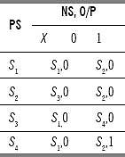
2. Design a two input two output sequence detector which generates an output ‘1’ every time the sequence 10101 is detected. And for all other cases output ‘0’ is generated. Overlapping sequences are also counted. Draw only state table and state diagram and make state assignment.
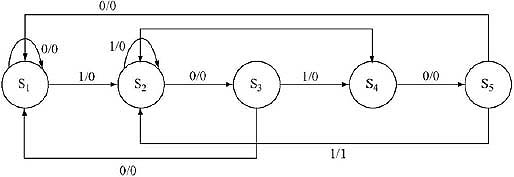
Ans. The state diagram is constructed above. Here the overlapping sequence is 101.
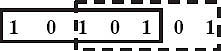
The state table for the sequence detector is
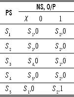
For doing state assignment we have to assign the states to some binary numbers. Here are 5 states so we have to take binary string of length three because 23 = 8 > 5.
Let assign
000 as S1, 001 as S2, 011 as S3, 010 as S4, 100 as S5,.
After doing the state assignment, the state table become
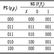
3. Find the equivalent partition for the machine given below.
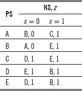
Ans. For string length 0 (i.e. for no input) there is no output, Hence all the states are equivalent. It is called 0-equivalent. Written as:
P0 = (ABCDE).
For string length 1, there are two types of inputs - 0 and 1. The states A and B give output 0 for input 0 and states C, D, and E give output 1 for input 0. All of the states give output 1 for input 1. Hence the states in the set P0 is divided into (AB) and (C, D, and E). Written as:
P1 = [(AB)(CDE)].
Here A and E are 1 distinguishable because they produce different outputs for input string length 1.
For input string length 2, check the distinguishability by next state combination.
The states A and B for input 0 produce next states B and A, respectively and produce next states C and E for input 1. B and A belong to same set, and C and E also belong to same set. Hence AB cannot be partitioned for input string length 2.
The states CDE for input 0, produce next states D,E, and D, respectively and produce next states E,B, and B for input 1. D and E belong to same set but B and E belong to different sets. Hence the set (CDE) is portioned into (C) and (DE). The new partition becomes
P2 = {(AB)[(C)(DE)]}.
For input string length 3, we have to perform similar to string length 2. The states A,B for input 0 produce next states B and A, respectively and produce next states C and E for input 1. The B and A belong to same set, but C and E belong to different set. So the set (AB) is partitioned into (A) and (B). C is a single state and cannot be partitioned further.
The state D and E produce next states E and D, respectively for input 0 and produce next states B for each of the states for input 1. D and E belong to same set. Therefore, D and E cannot be divided. The new partition becomes
P3 = (A)(B)(C)(DE).
Next we have to check for input string length 4. Three subsets contains single state - A, B, C and cannot be partitioned further.
The state D and E produce next state E and D, respectively for input 0 and next state B for each for input 1. D and E belong to same set, hence D and E cannot be partitioned further. The partition is same as P3. So the partition P3 is the equivalent partition of the machine.
Minimization:
We know that Equivalent Partition is unique. Therefore,
P3 = (A)(B)(C)(DE) is the unique combination. Here each single set represents one state of the minimized machine.
Let rename these partitions for simplification.
Rename (A) as S1, (B) as S2, (C) as S3, (DE) as S4.
The minimized machine becomes
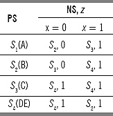
4. Find the equivalent partition for the machine given below.
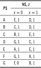
Ans. The partitions are:
P0 = (ABCDEFG),
P1 = (ABCDEF)(G),
P2 = (ABCE)(DF)(G),
P3 = (AB)(CE)(DF)(G),
P4 = (AB)(CE)(D)(F)(G),
P5 = (AB)(CE)(D)(F)(G).
As P4 and P5 are similar, P4 is the equivalent partition.
Minimization:
We know that equivalent partition is unique. Hence,
P4 = (AB)(CE)(D)(F)(G) is the unique combination. Here each single set represents one state of the minimized machine. Let rename these partitions for simplification.
Rename (AB) as Sl, (CE) as S2, (D) as S3, (F) as S4 and (G) as S5.
The minimized machine becomes
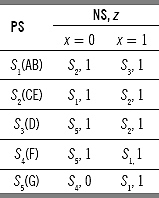
5. Find the equivalent partition of the machine given below.
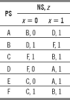
Ans. The partitions are:
P0 = (ABCDEF).
P1 = (ADE)(BCF) [Depending on o/p for i/p 0].
P2 = (ADE)(B)(CF) [For i/p 0 next state of B goes to another set].
P3 = (A)(DE)(B)(CF) [For i/p 0 next state of A goes to another set].
P4 = (A)(DE)(B)(CF).
As P3 and P4 are same so P3 is the equivalent partition.
Minimization:
We know that Equivalent Partition is unique. Therefore,
P4 = (A)(DE)(B)(CF) is the unique combination. Here each single set represents one state of the minimized machine. Let rename these partitions for simplification.
Rename (A) as S1 (B) as S2, (DE) as S3, and (CF) as S4.
The minimized machine becomes
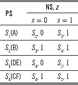
6. Find the equivalent partition of the machine given below.
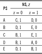
Ans. The partitions are:
P0 = (ABCDEF).
Pl = (AD)(BCE) [Depending on o/p for i/p 1].
P2 = (AD)(BE)(C) [For i/p 0 next state of C goes to another set].
P3 = (A)(D)(BE)(C) [For i/p 0 next state of A and D goes to different set].
P4 = (A)(D)(BE)(C).
As P3 and P4 are similar, P3 is the equivalent partition.
Minimization:
We know that equivalent partition is unique. Therefore, P4=(A)(D)(BE)(C) is the unique combination. Here each single set represents one state of the minimized machine.
Let rename these partitions for simplification.
Rename (A) as S1, (BE) as S2, (C) as S3, and (D) as S4.
The minimized machine becomes
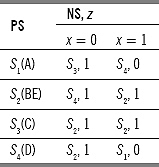
7. Simplify the following incompletely specified machine.
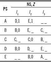
Ans. Put a temporary state T in the next state place, where next states are not specified. If the output is not mentioned, need to put any output. As a temporary state T is considered, so T is put in the present state column with next states T for all inputs with no output.
The simplified machine becomes
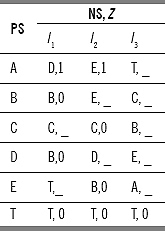
8. Minimize the following incompletely specified machine.
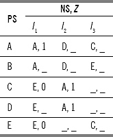
Ans. In an incompletely specified machine, all the next states or all the output or both are not mentioned. We can minimize an incompletely specified machine by using Merger graph and compatible graph method. From the merger graph we have to find compatible pair and from that compatible pair and implied pair we have to construct compatible graph. From compatible graph we have to find closed partition. And the closed partitions are the minimized states of the machine.
Merger Graph:
The machine consists of 5 states. So the merger graph consists of 5 nodes, named A, B, C, D and E. The outputs of A and B does not differ, hence there is an arc between A and B. For input I3, the next state conflicts – so the arc is an interrupted arc and in the interrupted portion conflicting next state pair (CE) is placed.
For state A and C the output conflicts, hence there is no arc between A and C.
For the states C and D the output as well as next states do not conflict. So an uninterrupted arc is placed between C and D. By this process the merger graph is constructed. The merger is as follows:
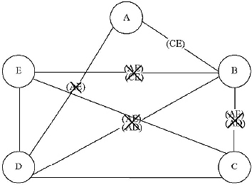
As there is no arc between A and E, the arc between (AD), (BE), (BD), and (BC) are also crossed.
Compatible graph:
The (CE) is the implied pair for (AB). A directed arc is drawn from (AB) to (CE). The compatible graph consists of four vertices (AB), (CD), (DE) and (CE).
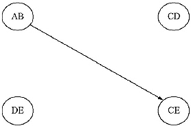
A subgraph of a compatibility graph is said to be closed cover for the machine if for every vertex in the subgraph, all outgoing edges and their terminal vertices also belong to the subgraph and every state of the machine is covered by at least one vertex of the subgraph.
For the constructed compatible graph (AB), (CD) and (CE) forms a closed covering. The states of the minimized machine are (AB) and (CDE). Rename (AB) as S1 and (CDE) as S2.
The minimized machine is
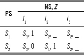
9. Construct Compatible graph for the following incompletely specified machine.
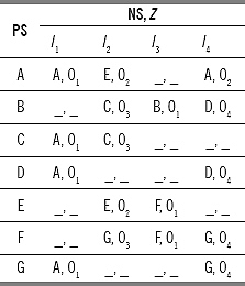
Ans. To construct compatible graph we have to first find compatible pairs. To find compatible pairs we need to construct Merger graph. Since this machine has 7 states, it is difficult to construct a Merger graph – hence we have to construct Merger table to find compatible pairs.
Merger table
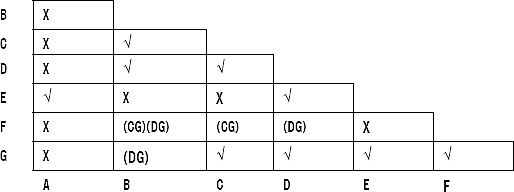
Compatible pairs are (AE), (BC). (BD), (CD). (CG), (DE), (DG), (EG), (GF) and
If (CG) and (DG) are compatible, then (BF) is compatible; If (DG) is compatible, then (BG) is compatible; If (CG) is compatible, then (CF) is compatible; If (DG) is compatible, then (DF) is compatible.
Compatible graph:
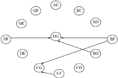
The closed partitions are (AE), (BF), (BG), (CF), (CG), (DF), and (DG). The states of the minimized machine are (AE), (BCDFG). Rename them as S1, S2
The minimized machine:
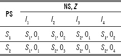
10. Test whether the following machine is finite or not.
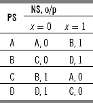
Ans.
Testing table–testing graph method
A table which is divided into two halves is made. The machine has two inputs and two outputs. There are four input–output combinations namely 0/0, 0/1, 1/0, and 1/1. The upper half of the machine contains single-state input–output combination and lower half contain two-state input–output combinations. There are four states, hence six combination pairs are made. The testing table is as follows:
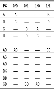
In testing table, there are six present states combinations. Therefore, in the testing table there are six nodes. There is a directed arc with label of input output combination, from SiSj [i ≠ j] to SpSq [ p ≠ q ] if SpSq is the implied pair of SiSj. The testing graph for finite memory:
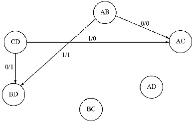
The testing graph is loop-free. Therefore, the machine is finite. The longest path in the testing graph is 1. The order of finiteness of the machine μ=1+1=2. This can be proved by vanishing connection matrix method.
In the testing table, six present state pairs are formed. Therefore, the connection matrix consists of six rows and six columns. The rows and columns are labeled with pair of present state combinations.
In the matrix, (ij)th entry will be 1 if there is an entry in (SaSb) (a ≠ b)and (SpSq)(p ≠ q) combination in the corresponding testing table. Otherwise the entry will be 0.
The connection matrix of the above machine is as follows.
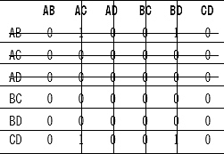
In the above matrix the rows AC, AD, BC and BD all contain 0s. Therefore the row labeled AC, AD, BC, and BD with the corresponding columns vanishes.
The remaining matrix becomes
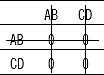
In the above matrix the row AB and CD contains all ‘0’. Therefore the rows labeled AB and CD with the corresponding columns vanish. The matrix vanishes. Number of steps required to vanish the matrix is 2. So order of finiteness of the machine μ = 2.
11. Test whether the following machine is finite or not.
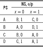
Ans.
There are four states, so six combination pairs are made. The testing table is as follows:
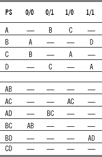
In testing table there are six present states combinations. Therefore, in the testing table there are six nodes. There is a directed arc with label of input–output combination, from SiSj (i ≠ j) to SpSq (p ≠ q) if SpSq is the implied pair of SiSj. The testing graph for finite memory:
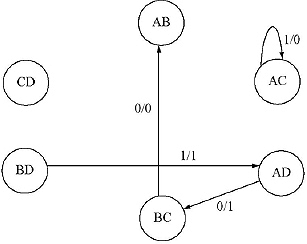
In the testing graph there is a loop from AC to AC with label 1/0. The testing graph is not loop-free. Therefore, the machine is not of finite memory. This can be proved by vanishing connection matrix method. In the testing table, six present state pairs are formed. Therefore the connection matrix consists of six rows and six columns. The rows and columns are labeled with pair of present state combinations. The connection matrix of the above machine is as follows:
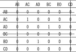
In the above matrix the row AB and CD contains all ‘0’. Hence the row labeled AB and CD and the corresponding column vanishes. The remaining matrix becomes:
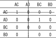
In the above matrix the row AD contains all ‘0’. Hence the row labeled AD and the corresponding column vanishes. The remaining matrix becomes:
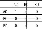
In the above matrix the row BC and BD contains all ‘0’. Hence the row labeled BC and BD and the corresponding column vanishes. The remaining matrix becomes:

The matrix does not vanish. Therefore, the machine is not of finite memory.
12. Test whether the following machine is finite or not.
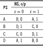
Ans. There are four states, hence six combination pairs are made. The testing table is as follows:
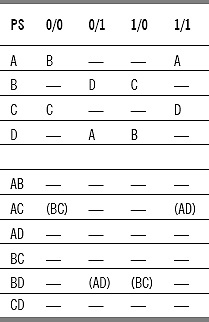
In testing table there are six present states combinations. Therefore, in the testing table there are six nodes. The testing graph for finite memory:
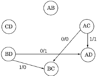
The testing graph is loop-free. Therefore, the machine is finite. The longest path in the testing graph is 1. The order of finiteness of the machine μ = 1 + 1 = 2.
Proof by Vanishing Connection Matrix
In the testing table, six present state pairs are formed. Therefore the connection matrix consists of six rows and six columns. The rows and columns are labeled with pair of present state combinations. The connection matrix of the above machine is as follows:
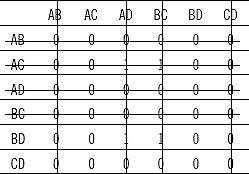
In the above matrix the rows AB, AD, BC and CD contains all ‘0’s. Therefore, the row labeled AB, AD, BC, and CD and the corresponding columns vanish.
The remaining matrix becomes:
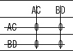
The matrix vanishes. Hence the machine is of finite memory. The connection matrix vanishes in two steps. Therefore the order of finiteness of the machine μ = 2.
13. Find whether the following machine is definite or not.
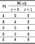
Ans. Whether a machine is definite or not definite can be checked by three methods: (a) synchronizing tree method, (b) contracted table method, and (c) testing table–testing graph method.
Synchronizing tree method: The present state combination of the machine is (ABCDE). It has two types of inputs 0 and 1. The (ABCDE) with input 0 produce next state combination (DACCA). It can be grouped into two distinct states (ACD). The (ABCDE) with input 1 produce next state combination (EBBBB) which can be grouped into (BE). In the next level, (ACD) with input 0 produces the next state combination (CD). With input 1, (ACD) produce next state combination (BE). The state combination (BE) with input 0 produces a single next state (A). With input 1, state combination (BE) produces single state B. As A and B are single state, it need not to be derived again. By this process (CD) and (BE) are also derived for input 0 and 1. The synchronizing tree:
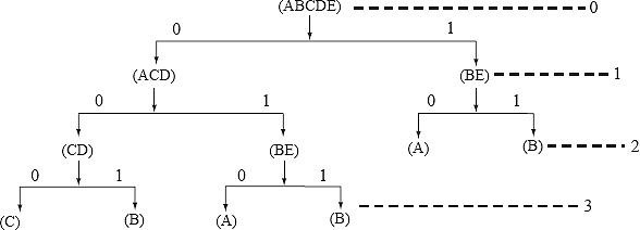
As the leaf nodes are of single state, stop constructing the tree. The order of definiteness is the maximum label of the synchronizing tree. In this case order is 3.
Contracted table method:
In the previous machine C and D have same next state combination (both cases C and B). The B and E also have same next state combination (both cases C and B). Therefore, C and D are equivalent states and B and E are also equivalent state. Among C and D lets consider only C and among B and E lets consider B. This implies all the D in the state table are replaced by C and all the E in the state table are replaced by B. The original and contracted table:
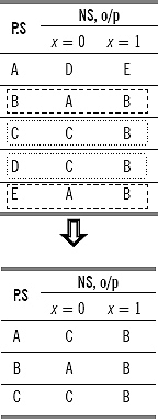
In the previous machine A and C have same next state combination (both cases C and B). Therefore, A and C are equivalent states. Among A and C let take only A. Implies all the C in the state table are replaced by A. The contracted table becomes:
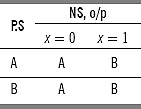
In the previous machine A and B have same next state combination (both cases A and B). Therefore, A and B are equivalent states. Among A and B lets consider only A. Implies all the B in the state table are replaced by A. The contracted table becomes:
The obtained table is consists of single row. Therefore, the machine is definite. Its order is the number of steps required to obtain the single state machine, here 3.
Testing table–testing graph method:
A table with two halves is made. The upper half contains input and next state combination. Lower half of the table contains all combination of present states taking two into combination. Here for five present states (A, B, C, D, and E) there are 5C2 means 10 combinations. The table:
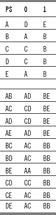
The testing graph:
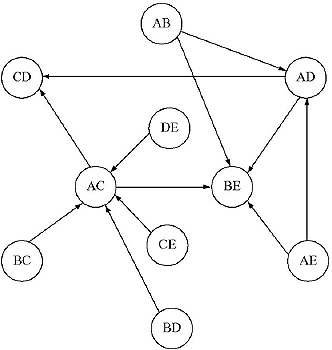
The testing graph is loop-free. So the machine is of definite memory. The longest path of the testing graph is 2 (AE ![]() AD
AD ![]() BE or AB
BE or AB ![]() AD
AD ![]() BE). Therefore order of definiteness of the machine is 2 + 1 = 3.
BE). Therefore order of definiteness of the machine is 2 + 1 = 3.
(We can use any of the methods to check definiteness of the machine. Among them contracted table method is the best. Synchronizing tree method good, but if the machine is not definite the leaf nodes of the synchronizing tree will not become single state. And the construction will be an endless process. If number of states of the machine is large then number of nodes will also be large. It will be difficult to construct testing table and testing graph.)
14. Find whether the following machine is definite or not.
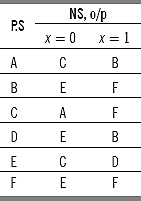
Ans. A machine is definite or not can be checked by three ways. But among them contracted table method is the best.
In the above machine B and F produce same next state (Both cases E and F). Therefore, B and F are equivalent state. Consider any of them e.g., B, implies all F in the state table is replaced by B. The contracted table from the original one:
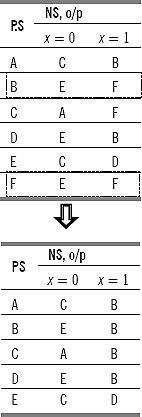
In the previous state table, B and D produce same next states (both cases E and B). Therefore they are equivalent states. Lets consider only B and replace all occurrences of D by B. The contracted table becomes:
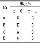
In the previous state table, A and E are equivalent states as they produce same next state combination (both cases C and B). Lets consider only A and replace all occurrences of E in the table by A. The contracted table:
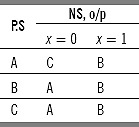
In the state table above B and C are equivalent states as they produce same next state combination for input 0 and 1. Let take only B and replace all occurrences of C in the table by B. The contracted table becomes:
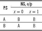
The state table does not become a single row table. Hence the machine is not definite.
15. Find whether the following machine is definite or not.
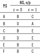
Ans. Contracted table method is used to check whether the given machine is definite or not. In the above machine present state C and E produce same next state combination for input 0 and 1. Same way A and F also produce same next state combination (both cases B and C). Therefore C and E are equivalent state and, A and F are equivalent states. Keep C and remove E from the present state column and replace all occurrences of E in the next state column by C. Similarly, keep A and remove F from the present state column and replace all occurrences of F in the next state column by A. The contracted table becomes:
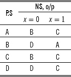
In the previous table A and C are equivalent states as they produce same next state combination for input 0 and 1. Remove C from present state column and replace all occurrences of C in the next state portion by A. The contracted table becomes:
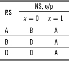
In the above state table B and D are equivalent state as they produce same next state combination for input 0 and 1. Consider B, remove D and replace all occurrences of D in the next state portion by B. The contracted table becomes:
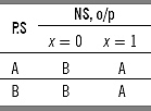
In the above state table A and B are equivalent states as they produce same next state combination for input 0 and 1. Replace B by A and remove B as a present state. The contracted table:
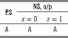
The obtained table is consists of single row. Therefore, the machine is definite. Its order is the number of steps required to obtain the single state machine, here 4.
16. Test whether the following machine is information lossless or not. If lossless find its order.
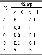
Ans. First step to test whether a machine is lossless or not, is to construct a testing table. The testing table is divided into two halves.
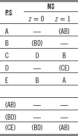
The testing table does not contain any repeated entry. The machine is information lossless machine.
The testing graph for the machine:
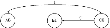
The testing graph for information losslessness is loop-free. The order of losslessness is μ = 1 + 2 = 3. The length of the longest path of the graph is 1.
16. Test whether the following machine is information lossless or not. If lossless find its order.
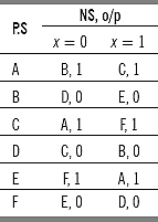
Ans. First we have to construct a testing table for information losslessness for testing whether the machine is information lossless or not. The testing table is divided into two halves.
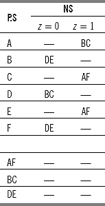
The testing table does not contain any repeated entry. The machine is information lossless machine.
The testing graph for the machine:
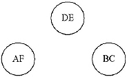
The testing graph for information losslessness is loop-free. The order of losslessness is m=0+2=2. The length of the longest path of the graph is 0.
17. Test whether the following machine is information lossless or not. If lossless find its order.
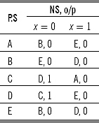
Ans. First we have to construct a testing table for information losslessness for testing whether the machine is information lossless or not. The testing table is divided into two halves.
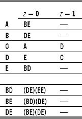
The testing table contains repeated entry (EE). The machine is lossy machine.
18. Test whether the following machine is information lossless or not. If lossless find its order.
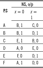
Ans. First we have to construct a testing table for information losslessness for testing whether the machine is information lossless or not. The testing table is divided into two halves.
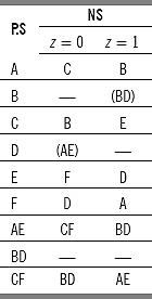
The testing table does not contain any repeated entry. The machine is information lossless machine. The testing graph for the machine:
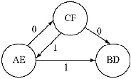
The testing graph contains loop. Hence the machine is not information lossless of finite order.
19. Find the input string which is applied on state ‘C' producing output string 1110000010 and final state ‘B’ for the machine given below.
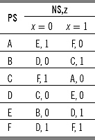
Ans. First, we need to prove the machine is information lossless. For this we need to construct a testing table for information lossless. If the machine is information lossless then and only a single input string can be found for a single beginning state and single final state.
The testing table for information lossless:
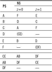
The testing table does not contain any repeated entry. The machine is information lossless machine. The output successor table for the given machine:
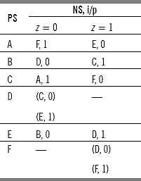
The input string is applied on state C and has produced output 1. From the output successor table it is clear that the next states are F with input 0. By this process the transition is as follows:
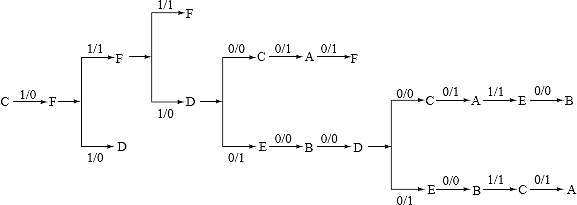
Beginning state C and final state B is obtained from one path with input string 0101000110.
20. Find the input string which is applied on state ‘D’ producing output string 10011110 and final state ‘D’ for the machine given below.
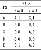
Ans. First we need to prove the machine is information lossless. For this we need to construct a testing table for information lossless. If the machine is information lossless then and only a single input string can be found for a single beginning state and single final state.
The testing table for information lossless:
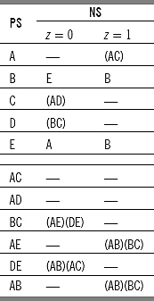
The testing table does not contain any repeated entry. The machine is output successor table for the given machine:
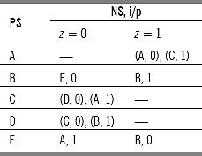
Transition is as follows:
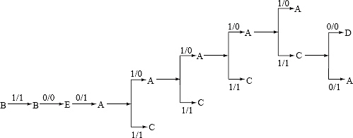
Beginning state B and final state D is obtained from one path with input string 10100010.
MULTIPLE CHOICE QUESTIONS
1. Operation of Synchronous circuits are controlled by
(a) Input
(b) State
(c) Output
(d) Clock pulses.
2. Output of Combinational circuit depends on
(a) Present state
(b) Past input
(c) Present input
(d) Present stored information and present input.
3. Output of sequential circuit depends on
(a) Present state
(b) Past input
(c) Present input
(d) Present stored information and present input.
4. For which of the following Finite state machine cannot be designed
(a) Addition of two binary numbers
(b) Subtraction of two binary numbers
(c) Multiplication of two binary numbers
(d) All of these
5. Two states are called 1 equivalent if
(a) Both of the states produce 1.
(b) If both of the states produce same output for string length 1.
(c) If both of the states produce same output for same input.
(d) If both of the states produce same output for input 1.
6. Which is true for incompletely specified machine?
(a) All Next states are not mentioned
(b) All outputs are not mentioned
(c) All inputs are not mentioned
(d) Both a and b.
7. Compatible pairs are obtained from
(a) Merger graph
(b) Compatible graph
(c) Testing table
(d) Testing graph.
8. Number of vertices of a Merger graph is
(a) The number of states of the machine
(b) Number of compatible pairs
(c) Number of states combinations
(d) None of these.
9. Number of vertices of a Compatible graph is
(a) The number of states of the machine
(b) Number of compatible pairs
(c) Number of states combinations
(d) None of these.
10. Merger Table is a substitution for
(a) Merger graph
(b) Compatible graph
(c) Testing graph
(d) Testing table.
11. A finite state machine M is called finite memory machine of order μ if present state of the machine M can be obtained from
(a) last μ number of inputs and corresponding μ number of next states
(b) last μ number of inputs and corresponding μ number of outputs
(c) last μ number of next states and corresponding μ number of outputs
(d) last μ number of inputs.
12. A sequential machine M is called definite if there exist a least integer μ, so that the present state of the machine M can be uniquely obtained from the
(a) Past μ number of inputs
(b) Past μ number of outputs
(c) Past μ number of next states
(d) Past μ number of inputs, outputs and next states.
13. Which is sufficient to find the initial state of an information lossless machine from the input string?
(a) Next state and output string
(b) Final state and Next state
(c) Final state and output string
(d) Final state, next state and output string.
14. Which is true of the followings?
(a) All information lossless machines are of finite order
(b) Some information lossless machines are of finite order
(c) Those machines which are not lossless of finite order are lossy.
(d) None of the above.
Ans. 1. d 2. c 3. d 4. c 5. b 6. d 7. a 8. a 9. b 10. a 11. b 12. a 13. c 14. b.
EXERCISES
1. Design a two input two output sequence detector which generates an output ‘1’ every time the sequence 0101 is detected. And for all other cases output ‘0’ is generated. Overlapping sequences are also counted.
2. Design a two input two output sequence detector which generates an output ‘1’ every time the sequence 1101 is detected. And for all other cases output ‘0’ is generated. Overlapping sequences are also counted.
3. Design a Modulo 8 binary counter using JK flip flop.
4. Find the Equivalent Partition for the machine given below
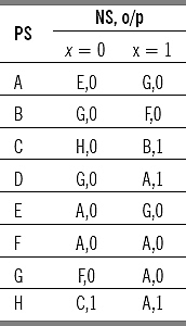
From here minimize the machine.
5. Find the Equivalent Partition for the machine given below
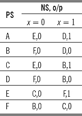
Find the shortest input sequence that distinguishes state A with state E. From here minimize the machine.
6. Simplify the following incompletely specified machine:
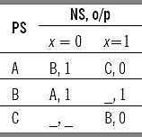
7. Simplify the following incompletely specified machine:
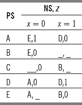
8. Find a minimal machine from the minimum machines for the machine given below considering the unspecified outputs as ‘0’ or ‘1’.
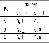
9. Develop a Merger Graph for the following incompletely specified machine. From there find the compatible pairs.
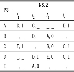
10. For the machine given above develop compatible graph and from there develop the minimal machine.
11. Develop Merger graph from the machine given below.
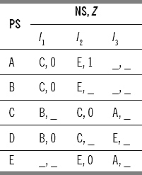
From there find the compatible pairs. Check either same compatible pairs are obtained or not from the Merger table constructed from the above machine
From the compatible pairs develop compatible graph and hence find the minimal machine.
12. Find whether the following machines are of finite memory or not by testing table–testing Graph and vanishing connection matrix method. If Finite find its order.
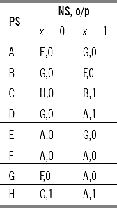
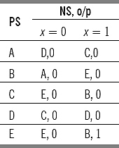
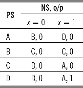
13. Test whether the following machines are definite or not by using synchronizing tree, contracted table and testing table–testing graph method. If definite find its order.
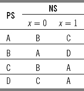
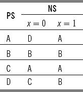
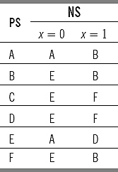
14. Find whether the following machines are information lossless or not. If lossless of definite order, find the order of losslessness.
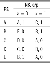
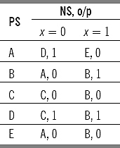
15. Find the input string applied to state A of the machine given below where final state is B and output string is 00011.
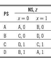
FILL IN THE BLANKS
1. Synchronous Circuit is controlled by ______________.
2. The operations in asynchronous circuit are controlled by a number of ______________.
3. The output of Combinational Circuits is a function of ______________.
4. The output of Sequential Circuits is a function of ______________.
5. Binary adder is a ______________.
6. Modulo 3 binary counter has____________ states.
7. Finite state machine can be defined as a type of machine whose past histories can affect its ____________ in a ____________ of ways.
8. Two states Si & Sj of machine M are said to be equivalent if they produce same ______________. for an ____________ applied to the machine M, considering Si and Sj as initial states.
9. If two states are k distinguishable then they are___________ equivalent for k = k to 1
10. Equivalent partition is ______________.
11. Incompletely specified machines are those machine where for all states for all inputs the ____________ or _________ or both are not mentioned
12. Minimal machine is the ___________of the machines obtained by minimizing an incompletely specified machine.
13. Merger graph of a machine M of n states is an ____________graph.
14. In a merger graph there will be an ______________ arc if the next states of the two states [Vertices] do not conflict.
15. In a Merger Graph there will be no arc between the two vertices if the____________ of the pair of states conflict.
16. Two states say Si & Sj are said to be compatible, if both of them give same __________strings for all _________ strings applied to the machine separately, considering Si & Sj as the initial states.
17. Compatibility graph is a __________ graph
18. A Subgraph of a Compatibility Graph is called______________ if for every vertex in the subgraph, all outgoing arcs and the terminal vertices of the arcs also belong to the subgraph.
19. Merger Table is a substitute application of ______________.
20. From a Merger Graph we can get the compatible pairs and ______________.
21. Vanishing connection Matrix is used to find whether a machine is ____________ or not.
22. Synchronizing Tree Method is used to find whether a machine is _____________ or not.
23. Contracted Table Method is used to find whether a machine is ______________ or not.
24. The order of definiteness μ = _________________if the length of the longest path in the Testing Graph is l.
25. The order of definiteness of a machine is the _________ of the synchronizing tree.
26. A machine is called information lossless if its __________ state, _____________ state & __________ string is sufficient to determine uniquely the input string.
27. A machine which is not lossless is called __________
ANSWERS
1. Clock Pulses
2. completion and initialization
3. Present I/P signals
4. External I/P & Present stored information
5. Sequential Circuit
6. Three
7. future behavior, finite number
8. output sequences, input string
9. k-1
10. Unique
11. Next State, output
12. Minimum
13. undirected
14. Uninterrupted
15. Outputs
16. Output, input
17. Directed
18. Closed
19. Merger Graph
20. implied pairs.
21. finite
22. definite
23. definite
24. l+1
25. Maximum Label
26. Initial, final, output
27. lossy