
3
Finite Automata
3.1 BASICS ABOUT FINITE AUTOMATA
Q. Define and describe the characteristics of an Automaton.
Ans. An automaton is a system where materials, energy or information are transformed and transmitted for performing some operation without direct human participation. Any automated machine can be given as example of automaton.
Characteristics of an automaton:
Input (I/P): Input is taken in each clock pulse. For each single instance of time t1, t2, t3,…, tn the input are taken as I1, I2, I3,…, In. As there are n number of input lines, n number of inputs will be taken in each single time instant. Input for each input line is finite and taken from a set called set of input alphabet Σ.
Output (O/P): Output is generated in each clock pulse. For each single instance of time t1, t2, t3,…, tm, the outputs are generated as O1,O2,O3,…, Om. Output generated from each output line is finite and belongs to a set called Output alphabet set.
State: At any discrete instant of time the automaton can be in one of the states q1, q2, q3,…, qn. State belongs to a set called ‘State’ Q.
State transition: At any instant of time the automaton must be in one of the states that belong to the set Q. By getting input in a clock pulse the automaton must reside in a state. The state, in which the automaton will reside by getting that particular input, is determined by state transition. The state transition is a function of present state and present input, which produces the next state. The function is represented as δ.
Output relation: Like state transition for state there is a relation for output. Output depends either on present state and present input or present state only depending on type of machine.
Q. Define finite automata. Why it is called finite?
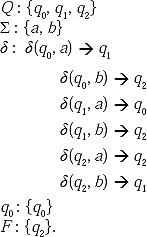
Ans. Finite automata (Singular: automaton) are the machine format of regular expression, which is the language format of type 3 grammar. A finite automata is defined as M = {Q, Σ, δ, qo , F}.
Where Q: Finite non-empty set of states.
Σ : Finite non-empty set of input symbols.
δ : Transitional function.
q0: Beginning state.
F : Finite non-empty set of final states.
Finite automata are a type of finite state machines. It has finite number of states. Finite automata can be thought of a finite state machine without output.
Q. Describe the graphical and tabular representation of finite automata.
Ans. Finite automata can be represented in two ways. (a) Graphical and (b) Tabular.
In graphical representation, a state is represented as ![]()
A beginning state is represented as ![]()
A final state is represented as ![]()
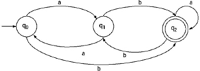
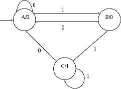
Here a finite automata is represented in graphical format.
Here,
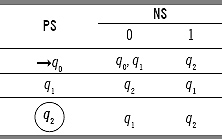
In tabular format a state is represented by the name of the state.
Beginning state is represented as:➞qn
Final state is represented as: ![]()
For the previous finite automata, the tabular format will be
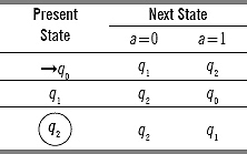
Here
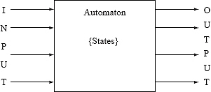
Q. Describe the block diagram or mechanical diagram of finite automaton. Describe each of the components.
Ans.
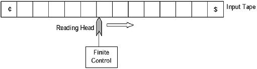
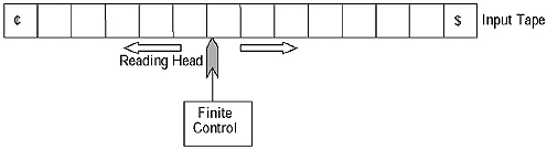
Input tape: Input tape contains the input symbol. It is divided into several squares, which contain single character of the input alphabet. Both left and right end of the input tape contain end markers. Between two end markers the input string is placed. This string is needed to be processed from left to right.
Reading Head: The head scans each square in the input tape and reads the input from the tape. The head can move from left to right or right to Left. But most of the cases the head moves from left to right. For two way finite automata and Turing machine the head can move in both directions.
Finite Control: Finite control can be considered as a control unit of a finite automaton. An automaton always resides in a state. The reading head scans the input from the input tape and sends it to finite control. In this finite control, it is decided that ‘the machine is in this state and it is getting this input, so it will go to this state’. The state transition relations are written in this finite control.
3.2 TRANSITIONAL SYSTEM
Q. Define transitional system. Mention the properties of transitional functions.
Ans. A transitional system (sometimes called transitional graph) is a finite directed graph in which each node (or vertex) represents a state and the directed arc indicates the transition of the state. The label of the arc indicates input or output or both. A transitional function has two properties.
Property I: δ(q, Λ) ![]() q.
q.
It means if input is given null for a state, the machine remains in the same state.
Property II: For all string Xand input symbol a ![]() Σ,
Σ,
![]()
Q. What are the conditions for declaring a string accepted by a finite automaton?
Ans. There are two conditions for declaring a String accepted by a finite automaton. The conditions are:
Condition I: The string must be totally traversed.
Conditions II: The machine must come to a final state.
In short it can be said that if δ(q0, W) = qn, where W is the string given as input to the FA, q0 is the beginning state and qn belongs to the set of Final states, then the string Wcan be said accepted by the FA.
If these two conditions are fulfilled then we can declare a string accepted by a finite automaton.
If any of the conditions is failed to be fulfilled then we can declare a string is not accepted by a finite automaton.
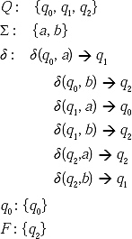
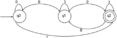
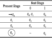
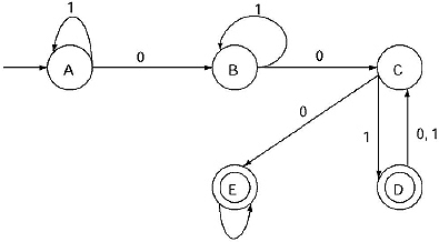
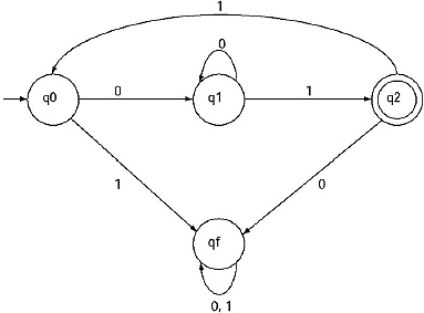
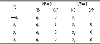
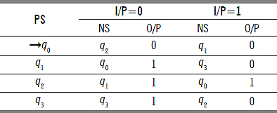
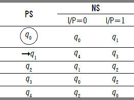
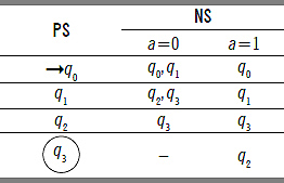
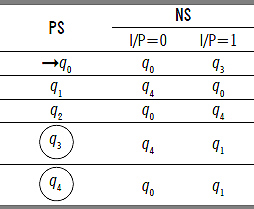
Q. Check whether the string 011001 is accepted or not by the FA given below.
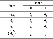
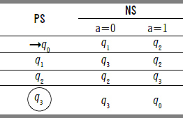
Ans. For the given FA Q = {q0. q1. q2. q3}, Σ = {0, 1}, Beginning State is q0 and final state is q3 The transitional functions are given in the table.
For checking whether a string is accepted by a FA or not we assume that the input string is given input in the beginning state q0. However, single input is given in each of the clock pulses. Therefore, at first the left most character is given input to the beginning state. From the transitional function given in the table the next state is determined. The next character of the input string is treated as input to the state just achieved. And it will process similarly till the string is finished or such a condition is arrived so that there is no transitional function mentioned in the table.
If the string is finished and the state achieved is final state then the string will be declared accepted by the machine. If it does not happen then the string will be declared not accepted.
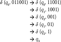
q3 is the final state of the FA. Therefore the two conditions for acceptability of a string by a FA are fulfilled. Hence the string 011001 is accepted by the given finite automata.
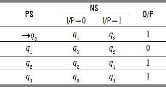
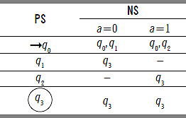
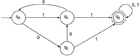
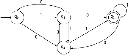
Q. Test whether the strings 010010, 01010 are accepted by the finite automata given below or not.
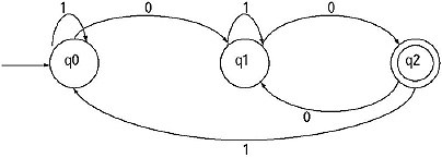
Ans.
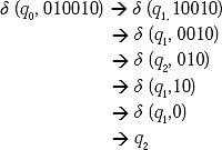
q2 is the final state of the FA. Hence the string 010010 is accepted by the FA.
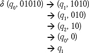
The ql is not final state of the FA. The String is finished. But the machine has not come to the final state. Hence the string is not accepted by the FA.
3.3 DETERMINISTIC FINITE AUTOMATA AND NON-DETERMINISTIC FINITE AUTOMATA
Q. Define deterministic finite automata (DFA) and non-deterministic finite automata (NDFA). Why are they called deterministic and non-deterministic, respectively?
Ans. Deterministic finite automata (DFA) is a finite automata where for all cases for a single input given to a single state the machine goes to a single state, i.e. all the moves of the machine can be uniquely determined by the present state and present input symbol.
A DFA can be represented as
MDFA = {Q Σ, δ, q0, F}.
Where δ is a transitional function mapping Q X Σ![]() Q, where |Q = 1|.
Q, where |Q = 1|.
Non-deterministic finite automata or NDFA (NFA) is a finite automata where for some cases for a single input given to a single state the machine goes to more than one states, i.e. some the moves of the machine cannot be uniquely determined by the present state and present input symbol.
MNFA = {{Q Σ, δ, q0, F}.
Where δ is a transitional function mapping QX Σ ![]() 2Q 2Q is the power set of Q.
2Q 2Q is the power set of Q.
(Power set means set of all subsets of the set. For a set with n number of elements number of subsets or power set is 2n. For the set {1,2,3}, the subsets are {}, {1}, {2}, {3}, {1,2}, {2.3}, {1,3}, {1,2,3}. Eight in total i.e. 23.)
Example:
Here for the state q0 for input 0 it can to q0 or q1. Hence it is an example of NFA.
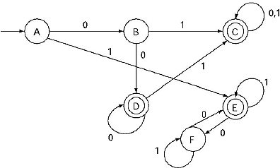
Q. Test whether the string ‘00101’ is accepted by the following finite automata or not.
Ans. In the previous given FA, we are seeing that from q0 for input 0 it can go to q0 and q1. That is for q0 for input 0 there are two paths. Let draw a transaction diagram to clarify:
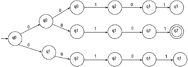
In the transaction diagram from q0 for input string 00101 we are getting three paths. For the string 00101 the last state we are getting as q1. q2. q1. Among them q2 is the final state. That is for the string 00101 from q0 we can reach to final state. Hence the string 00101 is accepted by the FA.
However, if someone follow path 1 and path 3, it will not be possible to reach to the final state. Then it can be declared that the string not accepted by the FA. That means it depends on the path which is being followed by the FA.
A String w ![]() Σ* is accepted by a NFA if δ(q0, w) contains some final state.
Σ* is accepted by a NFA if δ(q0, w) contains some final state.
Therefore, the string 00101 is accepted by the FA.
Q. Why do we need to convert a NFA to a DFA?
Ans. For a DFA, δ is a transitional function mapping Q X Σ ![]() Q, where |Q| = 1.
Q, where |Q| = 1.
For a NFA δ is a transitional function mapping QX Σ ![]() 2Q, 2Q is the power set of Q.
2Q, 2Q is the power set of Q.
For a NFA for a single input given to a single state the machine can go to more than one state. Hence for a NFA it will be hard to decide for a string to be accepted by the NFA or not.
If a NFA can be converted to a DFA then this type of problem will not arise.
Implies that we have to convert QX Σ ![]() 2Q to Q' X Σ
2Q to Q' X Σ![]() Q', where Q is the finite set of states for a NFA and Q' is the set of states for the converted DFA.
Q', where Q is the finite set of states for a NFA and Q' is the set of states for the converted DFA.
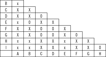
Q. What is the process of converting a NFA to a DFA?
Ans.
(i) Start from the beginning state of the NFA. Consider the state within [ ].
(ii) Place the next states for the beginning state for the given inputs. Put them also in [ ].
(iii) If any new combination of state appears, which is not yet taken in present state column; take that combination of state in the present state column.
(iv) If in the present state column more than one state appears, the next state for that combination will be the combination of the next states for each of the states.
(v) If no new combination of state appears, which is not yet taken in the present state column, stop the process.
(vi) Beginning state for the constructed DFA will be the beginning state of the NFA.
(vii) Final state or final states for the constructing DFA will be the combination of states containing at least one final state.
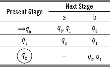
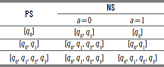
Q. Construct DFA from the given NFA.
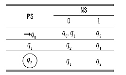
Solve:
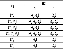
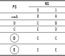
Lets replace [q0] as A, [q0, q1] as B, [q1. q2] as C, [q0, q1. q2] as D, [q2] as E and, [q1] as F
Then the constructed finite automata will be

In the finite automata, we see that in a single state, for a single input, the machine can go to only one state. Therefore, it is a DFA.
The beginning state is [q0] i.e. A. The final states are [q1. q2] i.e. C, [q0, q1. q2] i.e. D, and [q2] i.e. E.
The transaction diagram for the DFA will be as follows:
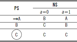
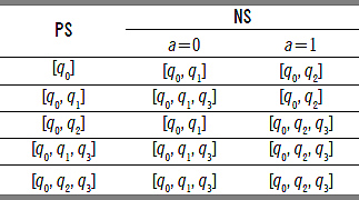
Q. Construct DFA from the given NFA.
Solve:
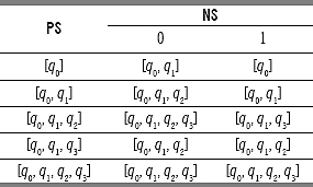
Let replace [q0] as A, [q0, q1] as B, [q0, q1, q2] as C, [q0, q1, q3] as D, [q0, q1, q2, q3] as E.
In the finite automata, we see that in a single state, for a single input, the machine can go to only one state. Hence it is a DFA.
Beginning state is A. Final state is D and E.
The transaction diagram for the DFA will be as follows.
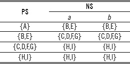
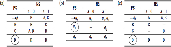
Q. Construct equivalent DFA for the given NFA.
Ans
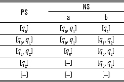
Here for the state q2 for input ‘a’ in the given NFA no state was mentioned. Therefore, we have taken it a new state [-], when converting from NFA to DFA. For the new state [-] as no next state was mentioned we have taken the same state [-] for both the inputs a and b.
(Soon we shall learn that these types of states are called dead state)
Let replace [q0] by A, [q0, q1] by B, [q1, q2] by C, [q2] by D, and [-] by E. The tabular representation will become:
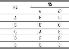
In the finite automata, we see that in a single state, for a single input, the machine can go to only one state. Therefore, it is a DFA. Beginning state is A; Final states are C and D.
The transaction diagram for the DFA is as follows:
3.4 NFA WITH NULL MOVE
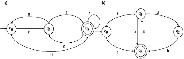
Q. What do you mean by NFA with e moves? Give an example. Why is it called NFA?
Ans. If any finite automata contains any e (null) move or transaction then that finite automata is called NFA with e moves. As an example
The previous finite automata contain two null moves. Hence the previous FA is NFA with null move. From the definition of NFA we know for a NFA from a single state, for a single input the machine can go to more than one state, i.e. Q X Σ → 2Q, where 2Q is the power set of Q.
From a state by getting ![]() input the machine is confined into that state. A finite automata with null move must contain at least one
input the machine is confined into that state. A finite automata with null move must contain at least one ![]() move. For this type of finite automata for input
move. For this type of finite automata for input ![]() the machine can go to more than one states. (One is that same state and another state is the
the machine can go to more than one states. (One is that same state and another state is the ![]() -transaction next state). Hence a finite automata with
-transaction next state). Hence a finite automata with ![]() move can be called as a NFA.
move can be called as a NFA.
For the previous finite automata
![]()
A NFA with ![]() move can be defined as
move can be defined as
MNFA null = {Q, Σ, δ, q0, F}.
Where Σ : Set of input alphabets including ![]() and
and
δ is a transitional function mapping Q X Σ → 2Q 2Q is the power set of Q.
Q. What is the usefulness of NFA with ![]() move? Explain with an example.
move? Explain with an example.
Ans. If we want to construct finite automata that accepts a language, sometimes it becomes very difficult or seems to be impossible to construct direct NFA or DFA. But if we use NFA with e moves, then the transitional diagram can be constructed and described easily.
Example: Lets assume, we are to construct a DFA that accepts any combinations of string of a, b, c, i.e. the string can start with a or b or c. After any symbol any of the symbols can come in any combination. The DFA for this:
However, it is not clearly understandable how any combination of a, b, c can appear. However, if we represent a transitional diagram as follow:
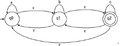
Then it is clearly understandable that the string can start with a or b or c, and for the null transitions from any state we can move to any other state with no input. Therefore, if c comes after ‘a’, we can go from q0 to q2 easily with no input. Same thing can occur for all the other states.]
Q. How to convert a NFA with e moves to an equivalent DFA?
Ans.Let in the NFA we want to remove the ![]() move, exists between states S1 and S2.
move, exists between states S1 and S2.
This can be removed in the following way
(i) Find all the edges [transitions] those start from the state S2.
(ii) Duplicate all these transitions starting from the state S1, keeping the edge label same.
(iii) If S1 is the initial state, also make S2 as initial state.
(iv) If S2 is the final state, also make S1 as the final state.
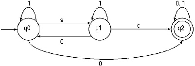
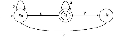
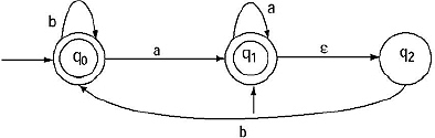
Q. Convert the following NFA with null move to an equivalent DFA.
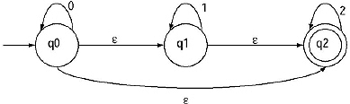
Ans. There are three null moves existing in the previous transitional diagram. The transitions are (i) From q0 to q1 (ii) From q1 to q2 (iii) From q0 to q2. We have to remove these null transitions step by step.
Step I: (a) Between state q0 and q1 there is a null move. If we want to remove that null transition, we have to find all the edges starting from q1. The edges are q1 to q1 for input 1, and q1 to q2 for input ![]() .
.
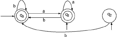
(b) Duplicate all these transitions starting from the state q0, keeping the edge label same. The q0 is initial state, hence make q1 also an initial state. The modified transitional diagram will be
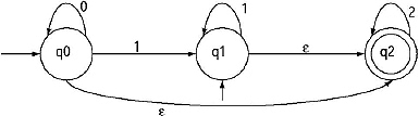
Step II: (a) Between q1 and q2 there is a null transaction. If we want to remove that null transition, we have to find all the edges starting from q2. The edge is q2 to q2 for input 2.
(b) Duplicate the transition starting from the state q1, keeping the edge label same. The q1 is initial state, hence make q2 also an initial state. The q2 is the final state, hence make q1 also final state. The modified transitional diagram will be
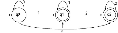
Step III: (a) Between q0 and q2 there is a null transaction. If we want to remove that null transition, we have to find all the edges starting from q2. The edge is q2 to q2 for input 2.
(b) Duplicate the transition starting from the state q0, keeping the edge label same. The q0 is initial state, hence make q2 also an initial state. The q2 is the final state, hence make q0 also final state. The modified transitional diagram:
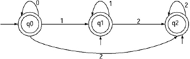
This the equivalent DFA obtained from the NFA with null transaction.
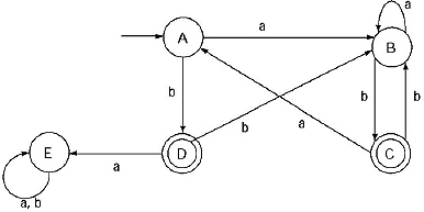
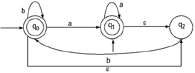
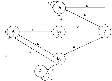
Q. Convert the following NFA with null move to an equivalent DFA.
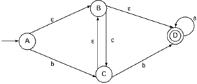
Ans. In the given NFA with ![]() move, there are three
move, there are three ![]() transitions: from A to B, from B to D, and from B to C. We will remove the three
transitions: from A to B, from B to D, and from B to C. We will remove the three ![]() transitions step by step.
transitions step by step.
Step I: There is a ![]() transition from A to B. If we want to remove that
transition from A to B. If we want to remove that ![]() transition, we have to find all the edges starting from B. The edges are B to C for input c and B to D for input
transition, we have to find all the edges starting from B. The edges are B to C for input c and B to D for input ![]() .
.
Duplicate the transition starting from the state A, keeping the edge label same. A is initial state, so make B also an initial state. The modified transaction diagram:
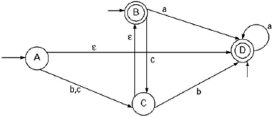
Step II: Again there are three ![]() transactions in the NFA. These are from A to D, from B to D and from C to B. Lets remove the
transactions in the NFA. These are from A to D, from B to D and from C to B. Lets remove the ![]() transaction from B to D. The edge starting from D is D to D for input a. Duplicate the transition starting from the state B, keeping the edge label same. As B is the initial state D will be also initial state. As D is the final state so B will be also final state. The modified transaction diagram will be
transaction from B to D. The edge starting from D is D to D for input a. Duplicate the transition starting from the state B, keeping the edge label same. As B is the initial state D will be also initial state. As D is the final state so B will be also final state. The modified transaction diagram will be

Step III: Now we are going to remove the ![]() transaction from A to D. The edge starting from D is D to D for input a. Duplicate the transition starting from the state A, keeping the edge label same. As A is the initial state D will be also initial state. As D is the final state so A will be also final state. The modified transaction diagram will be
transaction from A to D. The edge starting from D is D to D for input a. Duplicate the transition starting from the state A, keeping the edge label same. As A is the initial state D will be also initial state. As D is the final state so A will be also final state. The modified transaction diagram will be

Step IV: There is only one ![]() transaction from C to B. To remove this, find the edges starting from B. There are two, From B to D for input a and from B to C for input c. Start these edges from C. B is final state so make C as final state. The modified transitional diagram will be.
transaction from C to B. To remove this, find the edges starting from B. There are two, From B to D for input a and from B to C for input c. Start these edges from C. B is final state so make C as final state. The modified transitional diagram will be.
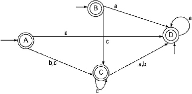
This the equivalent DFA obtained from the NFA with null transaction.
3.5 DEAD STATE
Q. Define dead state. What is the usefulness of Dead state? Explain with an example.
Ans. Dead state is a state where the control can enter and confined till the input ended, but no way to come out from that state.
For example, for the previous finite automata from q0 for input 0 there is a path to go to q1. But there is no path mentioned from q0 for input 1. Same thing happens for q2 also for input 0. Now let a string 101 is given to test the acceptability of the string by the finite automata.
According to the condition of the acceptability, the first condition i.e. the string will be totally traversed is not fulfilled. Obviously the second condition is not fulfilled.
We have to decide that the string is not accepted by the finite automata without traversing the string totally!
For making the string totally traversed we have to include an extra state, let qf, where the control will go from the states for which there is only one path for one input. In the state qf for the inputs there will be self loop. Here qf is the dead state.
By including dead state the finite automata will become
Now if we test for the acceptability of 101, the transitions are as follows
![]()
String is totally traversed and reached to qf . qf is not the final state, so the string is not accepted by the FA.
In the case we have seen that the string is finished [dead] by confined into qf. For this reason qf is called dead state.
3.6 FINITE AUTOMATA WITH OUTPUT
Q. Define Mealy Machine and Moore Machine.
Ans. Mealy Machine and Moore Machine are example of finite automata with outputs.
Mealy machine is one type of finite automata where output depends on present state and present input.
Moore machine is one type of finite automata where output depends on present state only but output is independent of present input.
Mealy Machine consists of six-touples:
M = (Q, Σ, Δ, δ, λ, q0)
where
Q : Finite non-empty set of states;
Σ : Set of input alphabets.
Δ : Set of output alphabets.
δ : Transitional function mapping Q X Σ → Q
λ : Output function mapping Q X Σ → Δ
q0: Beginning state.
Moore Machine consists of six-touples
M = (Q, Σ, Δ, δ, λ, q0)
where
Q : Finite non-empty set of states;
Σ : Set of input alphabets.
Δ : Set of output alphabets.
δ : Transitional function mapping Q X Σ → Q
δ : Output function mapping Q → Δ
q0: Beginning state.
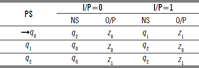
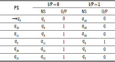
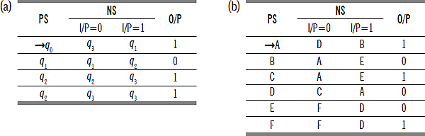
Q. Describe tabular representation of Mealy Machine and Moore Machine.
Ans. For Mealy machine the output depends on both present state and present input. So for mealy machine there will n number of output columns if there are n number of input.
So the tabular format of Mealy machine will be
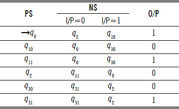
For Moore machine the output depends on present state only. As in a machine for present state there is only one Present state column, so there will be only one output column.
The tabular format of Moore machine will be.
Q. Describe the transitional diagram representation of Mealy machine and Moore Machine.
Ans.Mealy machine is one type of finite automata with output. Hence the transitional diagram will be like finite automata but output will be mentioned. For a Mealy Machine the output depends on present state and present input. Hence, for a Mealy machine the transitional arc will be labeled with both input and output.
Example:
Output of Moore machine depends only on the present state. For Moore machine the states will be labeled with state name and output.
Example:
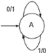
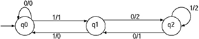
Q. Design a Mealy Machine to get complement of binary number.
Ans. For input 0 the machine will give output 1 and for input 1 the machine will give output 0. The Mealy machine:
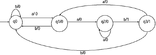
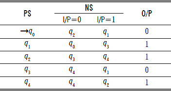
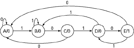
Q. Design a Moore Machine which will determine the residue mod-3 for each binary string treated as binary integer.
Ans. Binary string consists of two types of alphabet 0 and 1. Binary integer means the decimal equivalent of a binary string as integer numbers are taken as decimal. Residue mod-3 means the reminder that we get when the decimal equivalent of the binary number is divided by 3.
If a decimal number is divided by 3 we can get only 3 types of reminders, these are 0 or 1 or 2. We are constructing a Moore Machine, where output depends only on the present state. So, for three types of reminders (output) three states are needed.
Lets consider state q0 is producing output 0, state q1 is producing output 1 and state q2 is producing output 2. Now we need to construct the transitional arcs. Before construction take a table containing binary equivalent of decimal numbers from 0 to 9 and the reminders for each of them, when divided by 3.
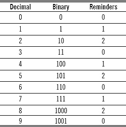
Input 0, output is 0. Therefore, transitional function will be δ(q0, 0) → q0, because q0 state produce output 0. Input 1, output 1, Hence, transitional function will be δ(q0, 1) → q1, because q1 state produce output 1. Input 10, output is 2. Hence, transitional function will be δ(q1, 0) → q2, because q2 state produce output 2. Input 11, output is 0. So, transitional function will be δ(q1, 1) → q0. By this process all the transitional functions can be produced.
Therefore, the Moore machine:
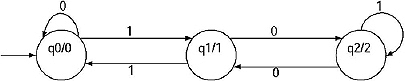
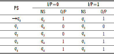
Q. Design a Mealy Machine which will determine the residue mod-3 for each binary string treated as binary integer.
Ans. The machine is a Mealy machine, so outputs depend on present state and present input.
For input 0, output is 0. Transitional function will be δ(q0, 0) → q0 and output function λ is q0 X 0 → 0. For input 1, output 1. Transitional function will be δ(q0, 1) → q1 and output function λ is q0 X 1 → 1. For input 10, output is 2. So, transitional function will be δ(q0, 1) → q1, and output function λ is q1 X 0 → 2. For input 11, output is 0. Hence, transitional function will be δ(q1, 1) → q0, and output function λ will be q1 X 0 → 0. By this process all the transitional functions will be constructed. The Mealy machine for this is
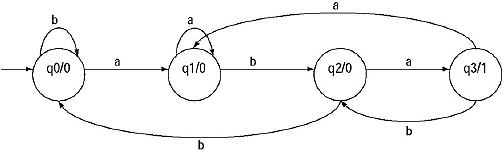
Q. Design a Moore machine which counts the occurrence of substring aba in a given input string.
Ans. It is one type of sequence detector. When the string aba will occur as a substring then output 1 will produced. For all the other cases output 0 will be produced (Overlapping sequences are also accepted).
We have to design a Moore machine, i.e. output depends only on the present state. For a string length of 3 we need four states if from a state with single input the machine goes to another new state. Let name the states as q0, q1, q2, q3. Except q3 all the states produce output 0. In state q0, we can get two types of input a or b. If we get ‘a’ then there is a chance to get ‘aba’. So it will move forward to q1. If we get ‘b’ then there is no chance to get ‘aba’ so it will confine to the same state. In q1, again two types of input can occur, ‘a’ and ‘b’. If we get ‘a’, then by considering this ‘a’ there is a chance to get ‘aba’. So it will confine to the same state. If we get b then we are two step forward to get ‘aba’. Hence the machine will move forward to state q2. In q2 if we get ‘b’ then there is no chance to get ‘aba’ except starting from the beginning. Hence it will go to q0. If we get ‘a’, we have got the string aba. Machine will go to state q3. In q3 if we get ‘a’, then again there is a chance to get ‘aba’. From q0, by getting ‘a’ the machine has moved forward to q1. So from q2 by getting ‘a’ the machine will go to q1. If we get ‘b’ then by considering the previous ‘a’ again there is a chance to get ‘aba’, so the machine will move to state ‘q2’.
From the above discussions the transitional functions can easily be derived. As it is Moore machine the outputs are included with the state (Output depends only on the present state not on the present input) so there is no need to derive the output functions. The Moore machine for the above problem:
Q. Design a Mealy machine which counts the occurrence of substring aab in a given input string.
The machine will be Mealy machine, i.e. output depends on the present state and present input. (Discussions will be like previous)
The machine:
3.7 CONVERSION OF MOORE TO MEALY MACHINE BY TABULAR FORMAT
Q. What is the procedure for converting a Moore Machine to a Mealy machine?
Ans.
(i) Draw the tabular format of Mealy machine.
(ii) Put the present states of the Moore Machine in the present state column of Constructing Mealy Machine.
(iii) Put the next states of Moore machine for corresponding present states and input combination, in the next state columns of the constructing Mealy Machine for the same present states and input combination.
(iv) For the output, look into the present state column and output column of the Moore Machine. The output for QNext (Next state for present state Qpresent and input I/P of the constructing Mealy Machine) will be the output for that state (QNt) as a present state in the given Moore Machine.
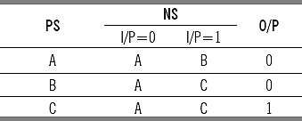
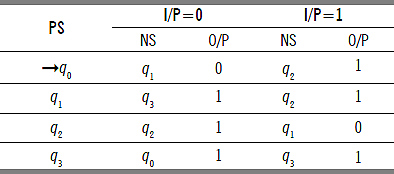
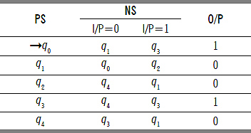
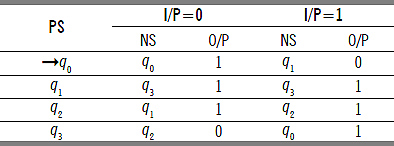
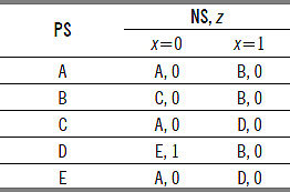
Q. Construct Mealy Machine equivalent to the given Moore Machine.
Solve:
In the Moore Machine, for q1 as a present state the output is 1. So in the constructing Mealy Machine for q1 as a next state the output will be 1.
In the Moore Machine, for q2 as a present state the output is 0. Hence in the constructing Mealy Machine for q2 as a next state the output will be 0.
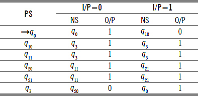
Q. Construct Mealy Machine equivalent to the given Moore Machine.
Solve:
Q. Construct Mealy Machine equivalent to the given Moore Machine.

Solve:
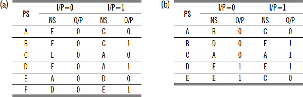
3.8 CONVERSION OF MEALY TO MOORE MACHINE BY TABULAR FORMAT
Q. What is the procedure for converting a Mealy Machine to a Moore machine?
Ans.
(i) Draw the tabular format of Mealy Machine first.
(ii) Look into the Next State and Output columns of the given Mealy Machine.
(iii) If for same Next state in the Next state column, the output differs in the output column, break the state q into different number of states. The number is equal to the number of different outputs associated with qi.
(iv) Put the states of the present state column in the new table. The states which are broken into number of different states, put the broken states in the place of those states.
(v) Change the next states in the next state columns according to the new set of states.
(vi) Put the output from the output column of the original Mealy Machine in the new machine also.
(vii) Draw the tabular format of Moore Machine.
(viii) Put the Present states and Next States from the constructed new Mealy machine to the constructed Moore machine.
(ix) For output look into the Next State and output column of the newly constructed Mealy Machine. For the state let qi, as a next state in the new constructed Mealy Machine if output is 0 then for qi, as a present state in the constructing Moore Machine; the output will be 0.
(x) For Moore Machine the output depends only on the present state. This means from the beginning state for ![]() input we can get an output. If the output is 1, the newly constructed Moore Machine can accept zero length string, which was not accepted by given Mealy machine. To make the Moore machine does not accept
input we can get an output. If the output is 1, the newly constructed Moore Machine can accept zero length string, which was not accepted by given Mealy machine. To make the Moore machine does not accept ![]() string, we have to add an extra state qb (new beginning state), whose state transactions will be identical with those of the existing beginning state but output is 0.
string, we have to add an extra state qb (new beginning state), whose state transactions will be identical with those of the existing beginning state but output is 0.
(For a Mealy machine with m number of states and n number of output, the Moore machine will be of n number of outputs but not more than mn + 1 number of states.)
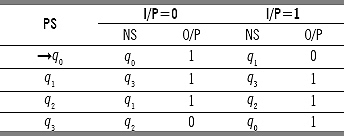
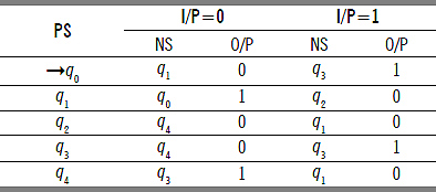
Q. Convert the given Mealy Machine to an equivalent Moore Machine.
Solve:
Look into the next state and output columns of the given Mealy Machine. For I/P 0 for q1 as a next state output is 1. For I/P 1 for q1 as a next state output is 0. Same thing happens for q2 as a next state for input 0 and input 1. So the state q1 will be broken as q10 and q11 and the state q2 will be broken as q20 and q21. After breaking the modified Mealy Machine will be
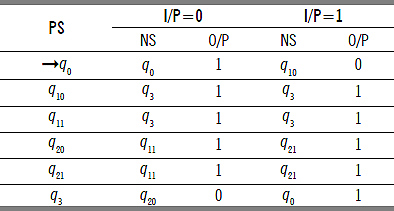
For present state q0 for input 1 the next state will be q10, because there is no q1 in the modified Mealy Machine. It has been broken into q10 and q11 depending on the output 0 and 1, respectively. For present state q0 for input 1 the output is 0. Hence the next state will be q10. Same cases occur for the others also. For the broken states the next states and outputs will be same as the original, from where the broken states have come.
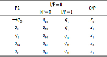
From this the Moore Machine will be
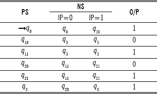
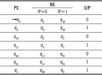
For Moore machine beginning state q0 and the output is 1. That means with null length input (no input) we are getting an output 1. Therefore, the Moore machine accepts 0 length sequence (Because here output depends only on the present state] which is not acceptable for mealy machine. To overcome this situation we must add a new beginning state qb with same transactions as q0 but output 0. By including the new state the Moore Machine will be.
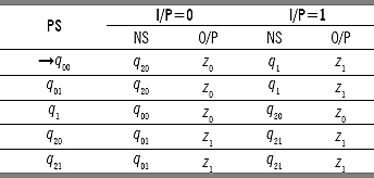
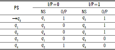
Q. Convert the given Mealy Machine to an equivalent Moore Machine.
Solve:
For q0 for input 0 the outputs differs. For q2 for input 0 and 1 the output differs. Therefore the states will be broken as q00, q01, and q20, q21. According to the new states the modified mealy machine:
From this modified mealy machine, the Moore machine will be
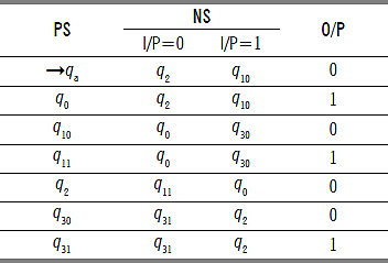
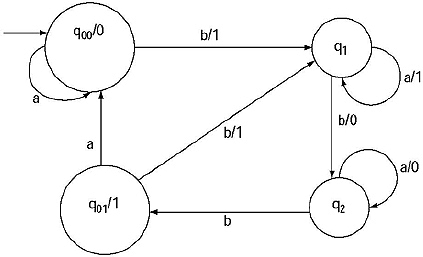
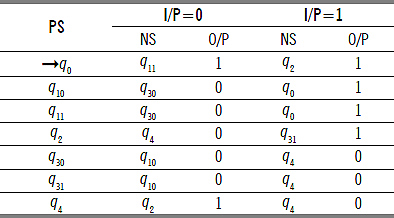
Q. Convert the given Mealy Machine to an equivalent Moore Machine.
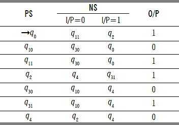
Ans. In the next state column of the given Mealy machine the output differs for ql and q3 as next state. Hence the states will be divided as q10, q11, and q30, q31, respectively. After dividing the states the modified Mealy machine will be
In the next state column of the modified mealy machine q0 as a next state output was 0. So for the constructing Moore Machine for present state q0 output will be 0. Same for present state q2 the output will be 0. For the divided states like q10, q11 there is no need to mention the output as they were divided according to the distinguished output. So the constructing Moore machine will be
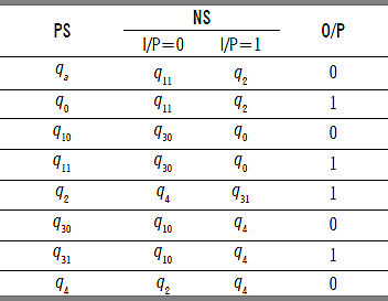
To get rid of the problem of occurrence of null string, we need to include another state let qa with same transactions as of q0 but with output 0.
The modified final Moore machine equivalent to the given Mealy machine will be
3.9 CONVERSION OF MOORE TO MEALY MACHINE BY TRANSITIONAL FORMAT
From the transitional diagram of a Moore or Mealy machine conversion can be done easily. That process is described here.
Q. Describe the process of conversion of Mealy machine from a given Moore machine.
Ans. Let a Moore machine Mo is to be converted to an equivalent Mealy machine MC. There are certain steps for this conversion.
Step I: For a Moore machine each state is labeled with output, as for Moore machine output depends only on the present state. For the conversion, let take a state S; which is labeled with output O. Look into the incoming edges to the state S. These incoming edges are labeled by the input alphabets of the Moore machine. These incoming edges will be relabeled by the input alphabet as well as the output of the state S. The output for the state will be removed.
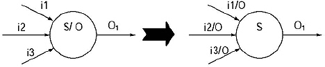
Process of conversion of Moore Machine to a Mealy Machine
Step II : Keep the outgoing edges from the state S as it was. (The outgoing edge of a state must be incoming edge of some other state.)
Step III: Repeat these steps for each of the states. By this we will get the Mealy machine equivalent Moore machine.
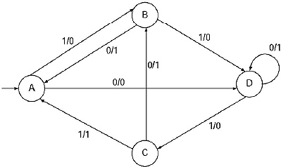
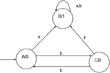
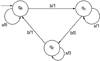
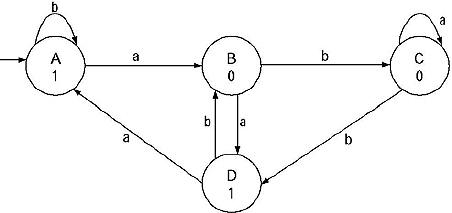
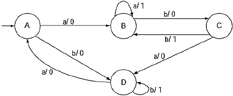
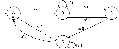
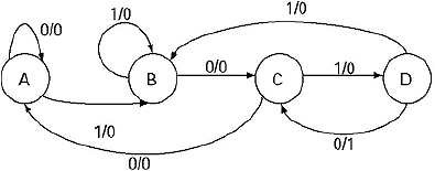
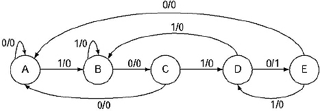
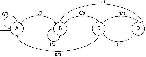
Q. Convert the following Moore machine into equivalent Mealy Machine.
Ans.
(a) In this machine A is the beginning state. Hence start from A. For A there are two incoming arc, from C to A with input b and one in the form of start state indication with no input. State A is labeled with output 0. As the start state indication contains no input, it is useless, keep it as it is.
Modify the label of the incoming edge from C to B including the output of state A. Hence the label of the incoming state will be C to A with label b/0.
(b) State B is labeled with output 1. The incoming edges to the state B are from A to B with input a, B to B with input a and b, and C to B with input a.
Modify the labels of the incoming edges including the output of state B. Hence the labels of the incoming states will be A to B with label a/1, B to B with label a/1 and b/1, and C to B with label a/1.
(c) State C is labeled with output 0. There is only one incoming edge to this state, from A to C with input b.
The modified label will be b/0.
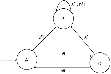
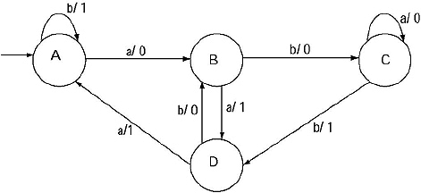
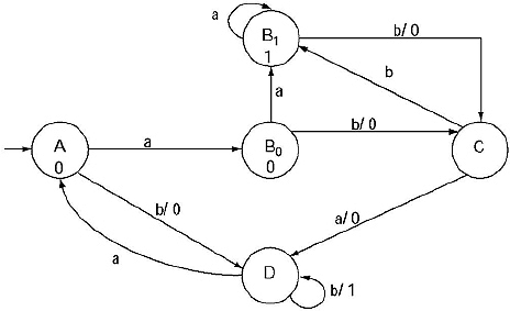
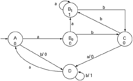
The converted Mealy machine:
Q. Convert the following Moore machine into equivalent Mealy Machine.
Ans. State A is labeled with output 0. The incoming edged to this state are C to A for input b, A to A for input b, and one as start state indication with no input. Ignore the edge with start state indication.
Modify the labels of the incoming edges by including the output of state A. So the modified labels will be, from A to A with label b/0, and from C to A with label b/0.
State B is labeled with output 0. The incoming edges to this state are, A to B for input a, B to B for input a, D to B for input a. The modified labels will be, A to B with label a/0, B to B with label a/0, D to B with label a/0.
State C is labeled with output 0. The incoming edges to this state are B to C for input b, and D to C for input b. The modified labels will be B to C with label b/0, D to C with label b/0.
State D is labeled with output 1. The incoming edge to this state is C to D for input a. The modified labels will be from C to D with label a/1.
The Mealy machine equivalent to the given Moore machine:
3.10 CONVERSION OF MEALY TO MOORE MACHINE BY TRANSITIONAL FORMAT
Q. Describe the process of conversion of Moore machine from a given Mealy machine.
Ans. For a given Mealy machine MC there is an equivalent Moore Machine Mo. These can be constructed in several steps.
Step I: In mealy machine output depends on present state and present input. Hence, in the transactional diagram of a mealy machine transactional edges are labeled with input as well as output. For a state two types of edges are there, incoming edges and outgoing edges. For incoming edges it may happen that the output differs for two incoming edges like the following:
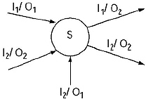
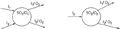
In the transitional diagram for state S, incoming edges are labeled as I1/01, I2/O2 and I2/O1 and the outgoing edges are labeled as I1/O2 and I2/O2. For state S for incoming edges we are getting two types of output O1 and O2. These types of cases the state S will be divided into n number of parts, where n = number of different outputs for the incoming edges to the state. The output edges will be repeated for all the divided states. The transitional diagrams for the above case will be
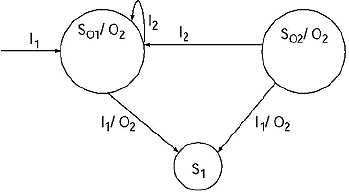
Step II: If a state has a loop and that state also need to be divided like follows:
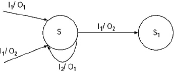
(Here for input I1, output is O1 as well as O2. Hence the state S needs to be divided. The S has a loop with input I2 and output O1.) The state S will be divided into two states So1 and So2. As the loop for input I2 is labeled with output O1, Hence there will be a loop on state So1. However, this loop is not possible on So2, because it produces output O2. Hence, there will be a transition from So2 to So1 with input label I2.
Step III: Repeat the steps I and II. By this we will get the Moore machine equivalent Mealy machine.
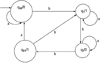
Q. Convert the following Mealy machine to an equivalent Moore machine.
Ans. For state q0, there are two incoming states, q0 to q0 with label a/0 and q2 to q0 with label b/1. Two incoming edges are labeled with two different outputs 0 and 1. Hence the state q0 need to be divided into two states let q00 and q01. There will be a loop for input ‘a’ on q00. There will a transition from q01 to q00 with input label ‘a’. From both the states there will be transitions to state q1 with label b/1. The modified machine will be
For all the other states q1 and q2 the outputs for all the incoming edges are 1 and 0, respectively. Hence there is no need to divide the states, the final Moore machine:
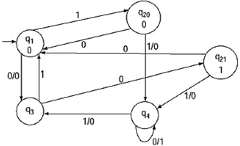
Q. Convert the following Mealy machine to an equivalent Moore machine.
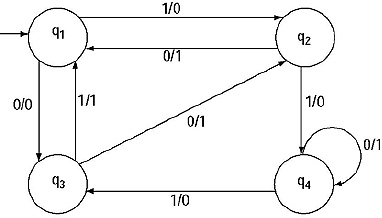
Ans. The machine contains four states. Lets start from the state q1. The incoming edges to this state are from q2 to q1 with label 0/1 and from q3 to q1 with label 1/1. There is no difference of the outputs of the incoming edges to this state therefore in the constructing Moore machine the output for this state will be 1. The modified machine:
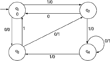
Consider the state q2. This state contains two incoming edges, from q1 to q2, with label 1/0 and q3 to q2, with label 0/1. There are two different outputs we are getting for two incoming edges (q1 to q2 output 0, q3 to q2 output 1). Therefore the state q2 will be divided into two, let name them q20 and q21. The outgoing edges are duplicated for both the states generated from q2.
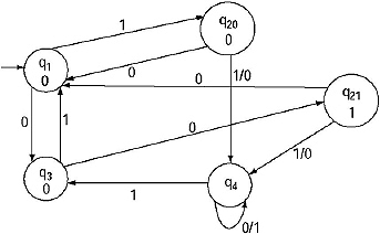
Consider state q3. The incoming edges to this state are, from q1 to q3 with label 0/0 and from q4 to q3 with label 1/0. There is no difference of the outputs of the incoming edges to this state, therefore in the constructing Moore machine the output for this state will be 0. The modified machine:
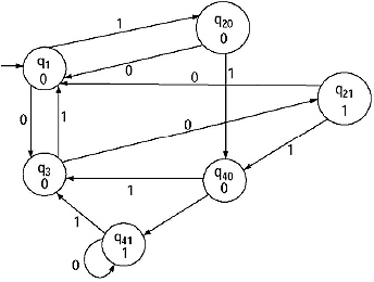
Consider the state q4. This state contains three incoming edges, from q20 to q4, with label 1/0, from q21 to q4 with label 1/0 and q4 to q4 with label 0/1. There are two different outputs we are getting for two incoming edges (q20 to q4 output 0, q21 to q4 output 0, q4 to q4 output 1). Hence the state q4 will be divided into two, let name them q40 and q41.
The modified Moore machine:
3.11 MINIMIZATION OF FINITE AUTOMATA
Q. What is the need of minimization of finite automata?
Ans. The language (regular expression) produced by a DFA is always unique. However, the reverse, i.e. a language produces a unique DFA is not true. Hence for a given language there may be different DFA s. By minimizing we can get a minimized DFA with minimum number of states and transitions which produces that particular language. DFA determines how computers manipulate regular languages (expressions). DFA size determines space/time efficiency. Hence from a DFA will minimized states need less time to manipulate a regular expression.
Q. Define dead state, inaccessible state, equivalent state, distinguishable state and k-equivalence in case of finite automata.
Ans. Dead State: A state qi is called dead state if qi is not a final state and for all the inputs to this state the transitions confined to that state. In mathematical notation, we can denote qi ![]() F and
F and ![]() (qi, Σ) → qi.
(qi, Σ) → qi.
Inaccessible state: The states which can never be reached from the initial state are called in accessible state.
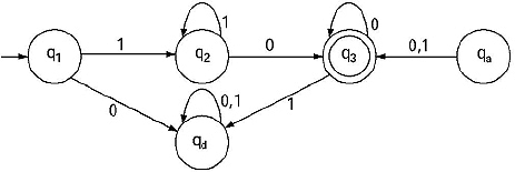
Here qd is dead state and qa is inaccessible state.
Equivalent State: Two states qi and qj of a finite automata M are called equivalent if ![]() (qi, x) and
(qi, x) and ![]() (qj, x) both produces final states or both of them produces non-final states for all x
(qj, x) both produces final states or both of them produces non-final states for all x ![]() Σ*. It is denoted by qi ≡ qj.
Σ*. It is denoted by qi ≡ qj.
Distinguishable State: Two states qi and qj of a finite automata M are called distinguishable if for a minimum length string x, for ![]() (qi, x) and
(qi, x) and ![]() (qj, x) one produces final state and another produces non-final state or vice versa for all x
(qj, x) one produces final state and another produces non-final state or vice versa for all x ![]() Σ*.
Σ*.
K-equivalent: Two states qi and qj of a finite automata M are called k-equivalent (k ≥ 0) if ![]() (qj, x) and
(qj, x) and ![]() (qj, x) both produces final states or both of them produces non-final states for all x
(qj, x) both produces final states or both of them produces non-final states for all x ![]() Σ* of length k or less.
Σ* of length k or less.
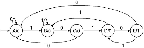
Q. Construct a minimum state automaton from the transitional table given below.
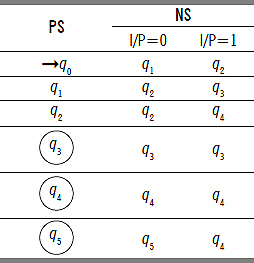
Solve:
In the finite automata, the states are {q0 ql q2 q3 q4 q5 }. Name this set as S0
S0: {q0 ql q2 q3 q4 q5 }. All of the states are 0 equivalent.
In the finite automata, there are two types of states final state and non-final states. Hence divide the set of states into two parts Q and q2.
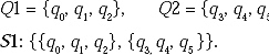
States belong to same subset are 1-equivalent because they are in the same set for string length 1. States belong to different subsets are l-distinguishable.
For input 0 and 1, q0 is going to ql and q2, respectively. Both of the states belong to same subset. For ql and q2 for input 0 and l the next states are q2, q3, and q2, q4, respectively. For both of the states for input 0 the next state belong to one subset and for input l the next state belong to another subset. Therefore, q0 can be distinguished from ql and q2.
The next states for input 0 and l for states q3, q4, q5 belong to same subset. Hence they cannot be divided.
![]()
q0 is the single state in the subset. Hence it cannot be divided.
For states ql, q2 for input 0 and l for both of the cases one state belong to one subset and another state belong to another subset. Hence they cannot be divided.
The next states for input 0 and l for states q3 q4, and q5 belong to same subset. Hence they cannot be divided.
Therefore in the next step
![]()
As step (n-l) and step n are same so we will stop here.
In the minimized automata number of states are 3.
The minimized finite automata in tabular format is
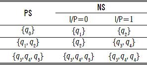
However, {q1} {q2}, {q3, q4} do not exist under the column of state. They are not states of the minimized finite automata, but they are subset of the states. In the next state columns by replacing the subsets by proper state the modified table will be.
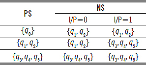
As q0 is the beginning state of the original finite automata {q0} will be the beginning state of minimized finite automata. As q3 q4, and q5 are the final states of the original finite automata so the set of the states containing any of the states as element will be final state. Here all the states are contained in a single set {q3, q4, q5 }, hence it is the final state. By replacing {q0} as A, {q , q2} as B and {q3 q4, q5} as C, the modified minimized finite automata will be.
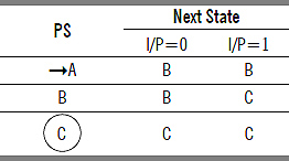
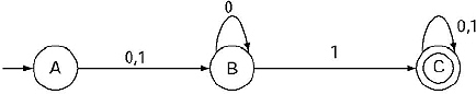
The transitional diagram of the minimized finite automata will be.
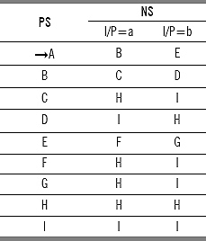
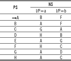
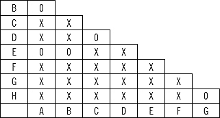
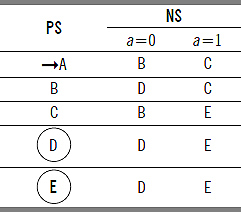
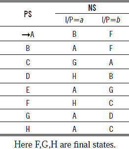
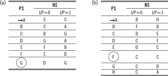
Q. Construct a minimum state automaton from the transitional table given below.
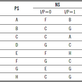
A is initial state and C is final state
Ans. In the finite automata the states are {A,B,C,D,E,F,G,H }. Name this set as S0
S0: {A,B,C,D,E,F,G,H }. All of the states are 0 equivalent.
In the finite automata there are two types of states final state and non-final states. Hence divide the set of states into two parts Q1 and Q2.
![]()
States belong to same subset are 1-equivalent because they are in the same set for string length 1. States belong to different subsets are 1- distinguishable.
The C is single state, hence it cannot be divided. Among the states {A,B,D,E,F,G,H} for {B,D,F,H} for input either 0 or 1, the next state belong to {C} which is different subset (From B with input 0 goes to C, from D with input 1 goes to C, from F with input 1 goes to C, H with input 0 goes to C).
For the other states {A,E,G} for input either 0 or 1 the next state belongs to Q2.
So Q2 can be divided into two parts {A,E,G} and {B,D,F,H}. Let name them Q3 and Q4.
The divided sets will be
S2: {{C}, {A,E,G}, {B,D,F,H}}.
Consider the subset of states {A,E,G}. A and E with input 0 and 1 both go to F,B and F,H, respectively, i.e. to the subset {B,D,F,H}. The G with input 0 and 1 go to E,G, i.e. the same subset. Hence {A,E,G} will be divided into two subsets {A,E} and {G}.
The subset {B,D,F,H} can be divided depending on the input and next state combination. B and H produce next state C and G for input 0 and 1, respectively.
The D and F produce next state G and C for input 0 and 1, respectively. Hence the set {B,D,F,G} will be divided into two subsets {B,H} and {D,F}.
The divided sets will be
S3: {{C}, {A,E}, {G}, {B,H}, {D,F}}.
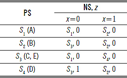
The subsets cannot be divided further. Hence these are the states of minimized DFA. Lets rename the subsets as q0, q1, q2, q3 and q4. Initial state was A, hence here initial state is {A,E}, i.e. q1. Final state was C, hence here final state is {C}, i.e. q0. The tabular representation of minimized DFA is
3.12 MYHILL-NERODE THEOREM
Q. Define Equivalence Relation and Right Invariant.
Ans.
(a) A relation R in set S is Reflexive if xRx for every x in S.
(b) A relation R in set S is symmetric if for x,y in S, yRx, whenever xRy.
(c) A relation R in set S is transitive if for xy and z in S, xRz whenever xRy and yRz.
A relation R in set S is called equivalence relation if it is reflexive, symmetric and transitive.
Right Invariant: An equivalence relation R on strings of symbols from some alphabet Σ is said to be right invariant if for all x, y ![]() Σ* with x R y and all w
Σ* with x R y and all w ![]() Σ* we have that xw R yw. This definition states that an equivalence relation has the right invariant property if two equivalent strings (x and y) that are in the language still are equivalent if a third string (w) is appended to the right of both of them.
Σ* we have that xw R yw. This definition states that an equivalence relation has the right invariant property if two equivalent strings (x and y) that are in the language still are equivalent if a third string (w) is appended to the right of both of them.
Q. State Myhill Nerode Theorem.
Ans. Myhill Nerode Theorem states that the following three statements are equivalent.
(a) The set L, a subset of Σ*, is accepted by a DFA, i.e. L is a regular language.
(b) There is a right-invariant equivalence relation R of finite index such that L is the union of some of the equivalence classes of R.
(c) Let equivalence relation RL be defined as xRLy, if and only if for all ![]() in Σ*, xz is in L exactly when yz is in L then RL is of finite index.
in Σ*, xz is in L exactly when yz is in L then RL is of finite index.
Q. How Myhill Nerode Theorem can be applied in minimizing a DFA?
Ans.
Step I: Build a two-dimensional Matrix labeled by the states of the given DFA at the left and bottom side. The major diagonal and the upper triangular part will be put dash.
Step II: One of the three symbols, X, x or 0 will be put in the locations where there is no dash.
(a) Mark X at p, q in lower triangular part such that p is final state and Q is non-final state.
(b) Make distinguished pair combination of the non-final states. If there are n number of non-final states there will be nC2 number of distinguished pairs.
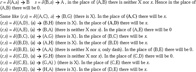
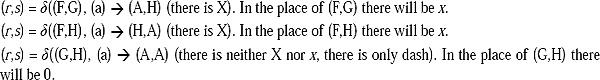
Take a pair (p, q) and find (r, s), such that r = ![]() (p, a) and s =
(p, a) and s = ![]() (q, a). If in the place of (r, s) there is X or x, in the place of (p, q) there will be x.
(q, a). If in the place of (r, s) there is X or x, in the place of (p, q) there will be x.
(c) If (r,s) is neither X nor x, then (p,q) will be 0.
(d) Repeat b and c for final states also.
Step III: The combination of states where there is 0, they will be the states of the minimized machine.
Q. Minimize the following DFA using Myhill Nerode theorem.
Here C,D,F,G are final states.
Ans.
Step I: Divide the states of the DFA into two subsets final (F) and non-final (Q-F).
F = {C,D,F,G}, Q-F = {A,B,E,H,I}.
Make a two-dimensional matrix labeled at left and button by the states of the DFA.
Step II: (a) The following combinations are the combination of beginning and final state.
(A,C), (A,D), (A,F), (A,G), (B,C), (B,D), (B,F), (B,G), (E,C), (E,D), (E,F), (E,G), (H,C), (H,D), (H,F), (H,G), (I,C), (I,D), (I,F), (I,G).
Put X in these combinations of states.
The modified matrix:
(b) The pair combination of non-final states are (A,B), (A,E), (A,H), (A,I), (B,E), (B,H), (B,I), (E,H), (E,I), (H,I).
r = ![]() (A,a) → B s =
(A,a) → B s = ![]() (B,a) → C, in the place of (B,C) there is X. Hence in the place of (A, B) there will be x.
(B,a) → C, in the place of (B,C) there is X. Hence in the place of (A, B) there will be x.
Same like (r,s) = ![]() ((?, E), (a) → (B, F) (there is X). In the place of (A,E) there will be x.
((?, E), (a) → (B, F) (there is X). In the place of (A,E) there will be x.
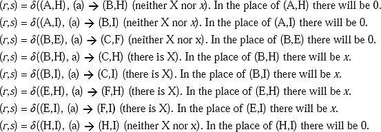
(c) The pair combination of final states are (C,D), (C,F), (C,G), (D,F), (D,G), (F,G).

The modified matrix will be
The combination of entries 0 are the states of the modified machine. The states of the minimized machine are [A], [B,E], [C,D], [C,F], [C,G], [D,F], [D,G], [F,G], [H,I].
For the minimized machine M”
Q' = ({A}, {B,E}, {C,D,F,G}, {H,I}).
[C,D], [C,F], [C,G], [D,F], [D,G] and [F,G] are grouped into single state [C,D,F,G] because all the previous combination of states are produced from these 4 states taking 2 states in a group.
Σ = {a,b}.
δ':
q'0 : {A}.
F' : {C,D,F,G}.
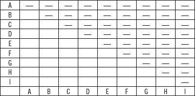
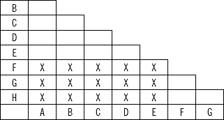
Q. Minimize the following finite automata by Myhill Nerode Theorem.
Here F,G,H are final states.
Ans.
Step I: Divide the states of the DFA into two subsets Final (F) and non-final (Q–F).
F={E,F,G}, Q–F = {A,B,C,D}
Make a two-dimensional matrix labeled at left and button by the states of the DFA.
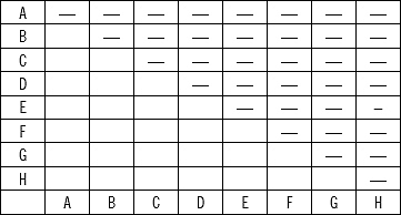
Step II: (a) The following combinations are the combination of beginning and final state.
(A,E), (A,F),(A,G),(B,E), (B,F),(B,G),(C,E),(C,F),(C,G),(D,E),(D,F),(D,G)
Put X in these combinations of states.
The modified matrix will be
(b) The pair combination of non-final states are (A,B), (A,C), (A,D), (A,E), (B,C), (B,D), (B,E), (C,D), (C,E), (D,E).
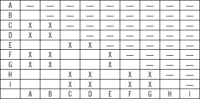
(c) The pair of combinations of final states are (F,G), (F,H), (G,H)
The modified table:
The combination of entries 0 are the states of the modified machine. The states of the minimized machine are (A,B), (A,E), (B,E) ,(C,D), (G,H), i.e. (A,B,E), (C,D), (G,H) and (F) (As F is a Final state of the machine but it is left in the state combinations).
(A,B, E) for input ‘a’ give output (A,B,A) and for input ‘b’ give output (F,F,G), where (F,F) belong to one set and (G) belong to another set. Therefore, it will be divided into (A,B), (E).
The states of the minimized machines are (A,B) ,(E), (C,D), (G,H) and (F). Let name them as S1, S2, S3, S4, S5
For the minimized machine M'
![]()
State table (Transitional function ![]() )
)
Q. Define Two way finite automata. Describe by an example.
Ans. Two way finite automata are machines which can traverse (read) an input string in both directions (Left and right).
A two way deterministic finite automata (2DFA) consists of 5 touples ![]() where Q, Σ, q0 and F are defined like one way DFA, but here transitional function
where Q, Σ, q0 and F are defined like one way DFA, but here transitional function ![]() is a map from Q X Σ to Q X (L,R). Here L means Left and R means right.?
is a map from Q X Σ to Q X (L,R). Here L means Left and R means right.?
Example:
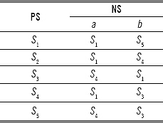
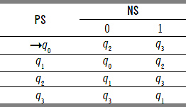
Consider a 2DFA, M given in the table
Let a string 101001 is given to check whether it is accepted by the 2DFA or not.
(A,101001) → (B, 01001R) → (B, 1001R) → (C,01001L) → (A,1001R) → (B,001R) → (B, 01R) → (B,1R) → (C,01L) → (A, 1R) → B
We have reached to the final state and the string is finished. Therefore the string 101001 is accepted by the 2DFA.
Q. Mention some applications of finite automata:
Ans. Finite automata can be applied in different fields of computer science and in different engineering fields. Some of them are spelling checkers and advisers, multi-language dictionaries, minimal perfect hashing and text compression. Perhaps the most traditional application is found in compiler construction where such automata can be used to model and implement efficient lexical analyzers.
WHAT WE HAVE LEARNED SO FAR
1. A finite automaton has five characteristics (a) Input (b) State (c) State Transition (d) output (e) output relation.
2. A finite automata M is represented as M = {Q, Σ, δ, q0, F}.
3. A string is declared accepted by a finite automata, if the string is finished and the machine reached to a final state.
4. Finite automata can be of two types (a) Deterministic finite automata (DFA) and (b) Non-deterministic finite automata (NDFA).
5. For a DFA for all cases for a single input given to a single state the machine goes to a single state, i.e. Q X Σ → Q.
6. For a NFA for some cases for a single input given to a single state the machine goes to more than one states, i.e. Q X Σ→ 2Q.
7. NFA can be constructed to an equivalent DFA.
8. A finite automata is called a NFA with null move if there exists a null transaction, i.e. Q X ![]() → Q.
→ Q.
9. Dead state is a state where the control can enter and confined till the input ended, but no way to come out from that state.
10. In Mealy Machine output depends on present state and present input.
11. In Moore Machine output depends on only present state.
12. Myhill Nerode Theorem is used to minimize a finite automata.
13. Two way finite automata are machines which can traverse (read) an input string in both directions (Left and right).
14. Finite automata is used in designing Lexical analyzer.
SOLVED PROBLEMS
1. Test whether the following string is accepted by the following finite automata or not.
(a) 0001101
(b) 01010
Ans.
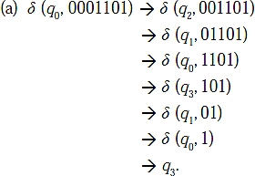
As q3 is the final state so the string is accepted by the given finite automata.
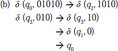
The q0 is a non-final state. Hence the string is not accepted by the given finite automata.
2. Test whether the following string is accepted by the following finite automata or not.
(a) 0111100
(b) 11010
Ans.
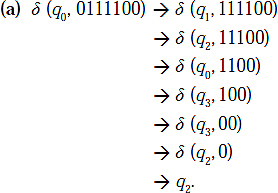
The q2 is the final state. Therefore, the string is accepted by the given finite automata.
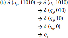
q1 is a non-final state. Therefore, the string is not accepted by the given finite automata.
3. Test whether the string 10010 is accepted by the following NFA or not.
Ans.
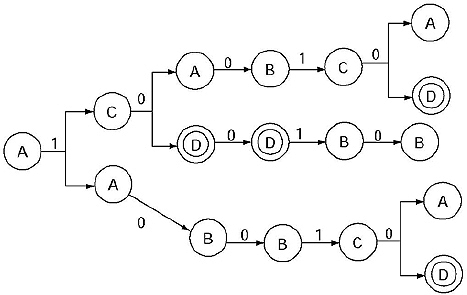
For the string 10010 we are getting terminal state as D which is a final state for two cases. Therefore, the string is accepted by the NFA.
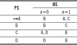
4. Convert the following NFA into an equivalent DFA.
Ans. This is an NFA because here for present state q0 with input 0 the control moves to q0, q1
For simplification let replace [q0] by A, [q0, q1] by B, [q0, q1, q2, q3] by C. Here A is the initial state and C is the final state as it contains the state q3.
The simplified DFA is
4. Convert the following NFA into an equivalent DFA.
Ans.
For simplification let replace [q0] by A, [q0, q1] by B, [q0, q2] by C. [q0, q1, q3] by D and [q0, q2, q3] by E. Here A is the initial state and D and E are The simplified DFA is q3.
The simplified DFA is
5. Convert the following NFA with e move to an equivalent DFA.
Ans. In the given automata there are two ![]() moves, from q0 to q1 and from q1 to q2. If we want to remove the first
moves, from q0 to q1 and from q1 to q2. If we want to remove the first ![]() moves, from q0 to q1 then, we have to find all the edges starting from q1. The edges are q1 to q1 for input a, and q1 to q2 for input
moves, from q0 to q1 then, we have to find all the edges starting from q1. The edges are q1 to q1 for input a, and q1 to q2 for input ![]() .
.
Duplicate all these transitions starting from the state q0, keeping the edge label same. The q0 is initial state, so make q1 also an initial state. The q1 is the final state, therefore make q0 as final state. The modified transitional diagram:
Again there are two ![]() moves, from q0 to q2 and from q1 to q2. If we want to remove the null transition from q0 to q2, we have to find all the edges starting from q2. The edges are q2 to q0 for input b. Duplicate this transition starting from the state q0, keeping the edge label same. The modified transitional diagram: (As in q0 there is a loop with label b, we need not to make another loop with the same label.)
moves, from q0 to q2 and from q1 to q2. If we want to remove the null transition from q0 to q2, we have to find all the edges starting from q2. The edges are q2 to q0 for input b. Duplicate this transition starting from the state q0, keeping the edge label same. The modified transitional diagram: (As in q0 there is a loop with label b, we need not to make another loop with the same label.)
If we want to remove the null transition from q1 to q2, we have to find all the edges starting from q2. The edges are q2 to q0 for input b. Duplicate this transition starting from the state q1, keeping the edge label same. Here q1 is initial state, hence make q2 also an initial state. The modified transitional diagram:
6. Convert the following Moore machine to equivalent Mealy machine by tabular format.
Ans.
The equivalent Mealy machine is
7. Convert the following Moore machine to equivalent Mealy machine by tabular format.
Ans.
The equivalent Mealy machine is
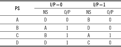
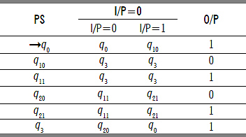
8. Convert the following Mealy machine to equivalent Moore machine by tabular format.
Ans. In the next state column of the given Mealy machine the output differs for ql and q3 as next state. Therefore, the states will be divided as q10 q11 and q30, q31, respectively. After dividing the states the modified Mealy machine:
The converted Moore machine is
To get rid of the problem of occurrence of null string, we need to include another state let qa with same transactions as of q0 but with output 0.
The modified final Moore machine equivalent to the given Mealy machine is
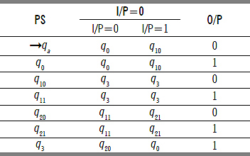
9. Convert the following Mealy machine to equivalent Moore machine by tabular format.
Ans. In the next state column of the given Mealy machine the output differs for q2 and q3 as next state. Therefore the states will be divided as q10. q11 and q20, q21, respectively. After dividing the states the modified Mealy machine will be
The converted Moore machine:
To get rid of the problem of occurrence of null string, we need to include another state let qa with same transactions as of q0 but with output 0.
The modified final Moore machine equivalent to the given Mealy machine:
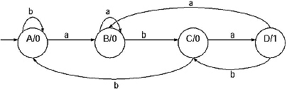
10. Convert the following Moore machine into equivalent Mealy Machine by transitional format.
Ans.
(a) In this machine A is the beginning state. Therefore start from A. For A there are three incoming arc, from A to A with input b and one in the form of start state indication with no input and the last is from D to A with input a. State A is labeled with output 1. As the start state indication contains no input, it is useless, keep it as it is.
Modify the label of the incoming edge from D to A and from A to A including the output of state A. Hence the label of the incoming state will be D to A with label a/1 and A to A with label b/1.
(b) State B is labeled with output 0. The incoming edges to the state B are from A to B with input a, D to B with input b. Modify the labels of the incoming edges including the output of state B. So the labels of the incoming states will be A to B with label a/0, D to B with label b/0.
(c) State C is labeled with output 0. There are two incoming edges to this state, from B to C with input b and from C to C with input a. The modified label will be B to C with label b/ 0, and C to C with label a/0.
(d) State D is labeled with output 1. There are two incoming edges to this state, from B to D with input a, and from C to D with input b. The modified label will be B to D with label a/1, and C to D with label b/1. The converted Mealy machine:
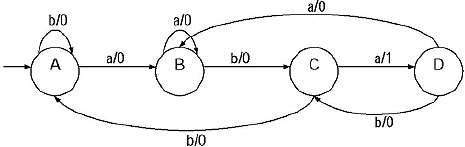
11. Convert the following Mealy machine into equivalent Moore Machine by transitional format.
Ans. The machine contains four states. Lets start from the state A. The incoming edges to this state are from D to A with label a/0. There is no difference of the outputs of the incoming edges to this state so in the constructing Moore machine the output for this state will be 0.
For the state B, the incoming edges are B to B with label a/1, from A to B with label a/0 and from C to B with label b/1.
There are two different outputs we are getting for two incoming edges (B to B output 1, A to B output 0). So, the state B will be divided into two, lets name them B0 and B1. The outgoing edges are duplicated for both the states generated from B. The modified machine:
For the state A, the incoming edges to this state are from B0 to C with label b/0 and B1 to C with label b/0. There is no difference of the outputs of the incoming edges to this state so in the constructing Moore machine the output for this state will be 0.
For the state D, the incoming edges are A to D with label b/0, from C to D with label a/0 and from D to D with label b/1.
There are two different outputs we are getting for two incoming edges (D to D output 1, C to D output 0). So, the state D will be divided into two, let name them D0 and D1. The outgoing edges are duplicated for both the states generated from D. The modified machine:
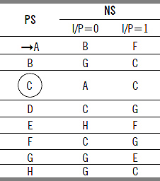
12. Minimize the following finite automata.
Ans. In the Finite automata the states are {A,B,C,D,E,F,G,H }. Name this set as S0.
S0: {A,B,C,D,E,F,G,H } All of the states are 0 equivalent.
In the finite automata, there are two types of states Final State and Non-Final States. So divide the set of states into two parts q1 and q2.
Q1 = {F, G, H}, Q2 = {A, B, C, D, E}.
S1: {{F, G, H} {A, B, C, D, E}}.
States belong to same subset are 1-equivalent because they are in the same set for string length 1. States belong to different subsets are 1- distinguishable.
The next states of F are H and C. The next states of G and H are A, D and A, C, respectively.
A, D and A, C belong to the same subset but H and C are belong to different subset. Hence, F, G, H are divided into {F}, {G, H}.
For input 0 the next states of A, B, C, D and E are B, A, G, H and A, respectively. For input 1 the next states of A, B, C, D and E are F, F, A, B and G, respectively. Hence, the set {A, B, C, D, E } is divided into {A, B, E} and {C, D}.
S2: {{F} {G, H} {A, B, E} {C, D}}
By the same process {A, B, E} is divided into {A, B}, {E}.
S3: {{F} {G, H} {A, B} {E} {C, D}} = {{A, B}, {C, D}, {E}, {F}, {G, H}}
The set further is not dividable. So these are the states of minimized DFA. Let rename the subsets as q0, q1, q2, q3 and q4. Initial state was A, Hence here initial state is {A,B}, i.e. q0. Final state were F, G and H, hence here final states are {F}, i.e. q3 and {G,H}, i.e. q4. The tabular representation of minimized DFA is
13. Design a Mealy and Moore Machine for detecting a sequence 1010 where overlapping sequences are also accepted. The Moore Machine that you have got, convert it to Mealy Machine. Are any differences coming? How will you prove that the two Mealy machines are equivalent?
Ans.
The Mealy Machine is
The Moore Machine:
The converted Mealy machine from the given Moore Machine is (By using transactional format)
This is surely different from the previously constructed Mealy Machine in number of states and in transactions.
But these two Mealy machines are equivalent. This can be proved by finding the equivalent partitions of the second machine.
The tabular format of the previous machine is
P0 = {A,B,C,D,E},
Pl = {A,B,C,E}{D},
P2 = {A,B}{C,E}{D},
P3 = {A}{B}{C,E}{D},
P4 = {A}{B}{C,E}{D}.
Rename the states as S1, S2, S3, S4
The machine is same as the first mealy machine.
MULTIPLE CHOICE QUESTIONS
1. A language L from a grammar G = { VN, Σ, P, S} is
(a) Set of symbols over VN
(b) Set of symbols over Σ,
(c) Set of symbols over P
(d) Set of symbols over S.
2. The transitional function of a DFA is
(a) Q X Σ→Q
(b) Q X Σ→2Q
(c) Q X Σ→2n
(d) Q X Σ→Qn
3. The transitional function of a NFA is
(a) Q X Σ→Q
(b) Q X Σ→2Q
(c) Q X Σ→2n
(d) Q X Σ→Qn
4. Maximum number of states of a DFA converted from a NFA with n states is
(a) n
(b) n2
(c) 2n
(d) None of these.
5. Basic limitations of finite state machine is
(a) It cannot remember arbitrarily large amount of information,
(b) In cannot remember state transitions,
(c) In cannot remember grammar for a language,
(d) It cannot remember language generated from a grammar.
6. The string WWR is not recognized by any FSM because
(a) A FSM cannot remember arbitrarily large amount of information,
(b) A FSM cannot fix the mid point,
(c) A FSM cannot match W with WR,
(d) A FSM cannot remember first and last inputs.
7. A finite automata recognizes
(a) Any Language
(b) Context Sensitive Language
(c) Context Free Language
(d) Regular Language.
8. Which is true for Dead State?
(a) It cannot be reached anytime,
(b) There is no necessity of the state,
(c) If control enters no way to come out from the state,
(d) If control enters FA deads.
9. Which is true for Moore Machine?
(a) Output depends on present state,
(b) Output depends on present input,
(c) Output depends on present state and present input,
(d) Output depends on present state and past input.
10. Which is true for Mealy Machine?
(a) Output depends on present state
(b) Output depends on present input
(c) Output depends on present state and present input
(d) Output depends on present state and past input?
11. Which is true for in accessible state?
(a) It cannot be reached anytime,
(b) There is no necessity of the state,
(c) If control enters no way to come out from the state,
(d) If control enters FA deads.
12. In Mealy Machine O/P is associated with
(a) Present state
(b) Next state
(c) Input
(d) None of these
13. In Moore Machine O/P is associated with
(a) Present state
(b) Next state
(c) Input
(d) None of these
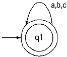
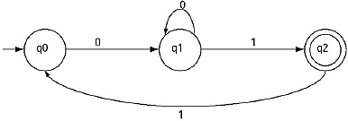
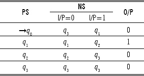
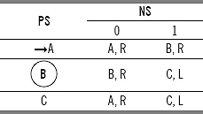
14. Which type string is accepted by the following finite automata?
(a) All string
(b) Null string
(c) No string
(d) None of these
![]()
Ans: 1. b 2. a 3. b 4. c 5. a 6. b 7. d 8. c 9. a 10. c 11. a 12. b 13. a 14. b
EXERCISES
1. Test whether the following strings are accepted by the given finite automata or not.
(a) 01010
(b) 1010100
(c) 0100101
2. Test whether the following strings are accepted by the given finite automata or not.
(a) 100010
(b) 0001101
(c) 1000
3. Test whether the following string 101001 is accepted by the given finite automata or not taking all possible combination of transitional path.
Why are you getting different result? Explain.
4. Convert the following NFA s into equivalent DFA s. (a)
5. Convert the following NFA s with null move to equivalent DFA s.
6. Convert the following Moore Machines into equivalent Mealy Machines.
7. Convert the following Mealy Machines into equivalent Moore Machines.
8. Convert the following Moore Machine into equivalent Mealy machine by transitional format.
9. Convert the following Mealy Machine into equivalent Moore machine by transitional format.
10. Minimize the following finite automata by finding equivalent state method.
11. Minimize the following finite automata by MyHill Nerode Theorem.
FILL IN THE BLANKS
1. A Finite Automata is defined as M = {—, —, —, —, —}.
2. Finite Automata is one type of __________ state machine
3. In graphical format representation of finite automata by double circle __________ state is represented.
4. In tabular format representation of finite automata by single circle __________ state is represented.
5. In block diagram of Finite automata input from input tape is read by __________.
6. Finite control can be considered as a __________ unit of a Finite automaton.
7. If input is given null for a state of Finite Automata, the machine goes to the __________.
8. There are two conditions for declaring a String accepted by a Finite Automaton. The conditions are __________ and __________.
9. For DFA the transitional function δ is represented by Q X Σ → __________.
10. DFA is a Finite Automata where for all cases for a single input given to a single state the machine goes to a __________ state.
11. In NFA δ is a transitional function mapping Q X Σ → __________.
12. If any Finite Automata contains any ![]() (null) move or transaction then that Finite Automata is called __________ with
(null) move or transaction then that Finite Automata is called __________ with ![]() moves.
moves.
13. A state where the control can enter and confined till the input ended, but no way to come out from that state is called __________.
14. Mealy Machine and Moore Machine are example of Finite Automata with __________.
15. For Mealy machine the output depends on __________ and __________.
16. For Moore machine the output depends on __________.
17. The states which can never be reached from the initial state are called __________ state.
18. A relation R in set S is called equivalence relation if it is __________, __________ and __________
19. A relation R in set S is __________ if for x, y in S, yRx whenever xRy.
20. A relation R in set S is __________ if for x, y and z in S, xRz whenever xRy and yRz.
21. R is __________ then for all x, y and z , xRy => xzRyz.
22. Myhill-Nerode Theorem is used for __________.
23. A two way finite automata is like Finite Automata but can traverse in __________.
24. Lexical analyzer is designed by __________.
25. Maximum number of states of a DFA converted from a NFA with n states is __________.
26. A Finite Automata recognizes __________ language.
ANSWERS
1. Q, S, 8, q0, F
2. finite
3. final
4. final
5. Reading head
6. Control
7. same state
8. string must be totally traversed, The machine must come to a Final state
9. Q
10. Single
11. 2Q
12. NFA
13. Dead State
14. outputs
15. present state, present input
16. Present State
17. in accessible
18. reflexive, symmetric, transitive
19. symmetric
20. transitive
21. right invariant
22. Minimization of FA
23.Both direction
24. Finite Automata
25. 2n