This chapter explains the Enhanced Interior Gateway Routing Protocol (EIGRP) concepts and technologies. These concepts are common to all three protocol families supported by EIGRP (IP, IPX, and AppleTalk) and are covered in several sections:
"Introduction to EIGRP" compares EIGRP to other routing protocols.
"Initial IP EIGRP Configuration" documents the basic commands needed to start IP EIGRP in the Cisco IOS.
"EIGRP Concepts" explains EIGRP Metrics and Distances.
"DUAL—The Heart of EIGRP" describes the core algorithm of EIGRP.
EIGRP data structures, protocols, and advanced concepts are covered in Chapter 2, "Advanced EIGRP Concepts, Data Structures, and Protocols." The IPX EIGRP and AppleTalk EIGRP configurations are covered in Chapter 3, "IPX EIGRP," and Chapter 4, "AppleTalk EIGRP."
You can better understand the technology used in EIGRP by comparing it with other protocols well known to the internetworking industry. As you know, routing protocols have two major approaches:
Routing by rumor (also called distance-vector) is used by protocols, such as Interior Gateway Routing Protocol (IGRP), Routing Information Protocol (RIP), and Border Gateway Protocol (BGP), where each router knows only what its neighbors tell it.
Routing by propaganda (also called link-state) is used by protocols, such as Open Shortest Path First (OSPF) or Intermediate System-to-Intermediate System (IS-IS), where all the routers in a region of the network share a common understanding of the region's topology.
Technology used in EIGRP (DUAL—Diffused Update Algorithm) is similar to distance vector protocols:
The router uses only the information it receives from its directly connected neighbors to make its routing decisions. Received information can be further filtered for security or traffic-engineering reasons.
The router announces only the routes it's using to its directly connected neighbors. Information sent to neighbors can also be filtered before being sent.
However, a number of significant differences make EIGRP perform better than traditional distance-vector protocols:
EIGRP stores all routes received from all neighbors in its topology table, not just the best route it has received so far. (Compare that with RIP, which stores only the best route and discards all others.) Knowledge of more than one route enables EIGRP to quickly switch to an alternate route should the current route disappear.
EIGRP takes an active role and queries its neighbors when a destination becomes unreachable and it has no alternate route. Routers running traditional distance-vector protocols passively wait for their neighbors to find better routes and report them. Because the convergence process is active, rather than passive (just waiting for a route to time out), EIGRP's convergence is comparable to the best link-state protocols.
Definition
Topology table is the data structure where EIGRP stores all routes it has received from its neighbors.
EIGRP uses the hello protocol between the neighbors to enable early detection of neighbor failure and faster convergence. Normal distance-vector protocols rely on routing update timeouts to detect this condition.
EIGRP uses the reliable transport protocol to send and receive routing updates, which eliminates the need for periodic full updates.
These features make EIGRP a modern routing protocol with convergence and link-usage performance comparable to other modern protocols, such as OSPF or IS-IS.
Initial IP EIGRP configuration is extremely simple:
Note
The as-number used in the EIGRP process does not have to be the globally unique Autonomous System number assigned to service providers and multihomed end-customers in the Internet by numbering authorities such as InterNIC or RIPE. You can use any number as long as you use the same number on all the routers running EIGRP. If you own a legal Autonomous System number, it's recommended that you use that number for consistency.
When a major network is specified in the EIGRP process with the network command, all the directly connected subnets of that major network are entered in the EIGRP topology table, EIGRP neighbors are discovered on all the interfaces belonging to the specified major network, and the routing information is exchanged with those neighbors. If you use several major networks in your internetwork (for example, if you're using private class-C address space 192.168.1.0—192.168.255.0), only those networks that directly connect to the router must be specified with the network command.
Note
You can use the passive-interface router configuration command, described in more detail in Chapter 2, to stop EIGRP from running on an interface that belongs to a major network specified with the network command. However, you can't stop EIGRP from inserting the directly connected subnets belonging to the major network specified in the network command into the topology table and propagating them to other EIGRP-speaking routers prior to IOS 12.0(4)T. The mask option of the network command was introduced in IOS 12.0(4)T to give EIGRP true classless behavior.
These two commands are usually the only two commands that you need to configure IP EIGRP in a small enterprise network. Additional EIGRP configuration is necessary in larger networks for fine-tuning or to deploy the scalability features.
Like any other protocol, EIGRP uses metrics to select the best route toward the destination. This section explains the two types of metrics that EIGRP uses: the vector metric and the composite metric. The rules for adjusting vector metric and the conversion process between vector and composite metric are defined.
Unlike other routing protocols, such as RIP or OSPF, EIGRP performs a two-step process in computing the metric of a route. Several different properties are associated with a route (vector metric):
Total delay from the router to the destination subnet
Minimum bandwidth on the path to the destination subnet
Maximum load and minimum reliability of any link on the path toward the destination subnet
Minimum MTU of any link toward the destination subnet
Hop count
The vector metric is used in combination with K-values to compute a single number called composite metric and sometimes distance. This number is used in all comparisons when the router is trying to decide which route is the best.
Definition
Vector metric is a six-element vector containing parameters (bandwidth, delay, load, reliability, hop count, and MTU) that describe the distance between a router and the destination subnet. The vector metric is used in all EIGRP routing updates.
Composite metric or Distance is an integer number used to compare different routes toward the same destination subnet. It's only used internally in the router and is never sent to EIGRP neighbors. EIGRP distance is completely unrelated to IOS administrative distance.
K-values are numbers (K1 through K5) used in transformation of vector metrics to a composite metric.
The formula to transform vector metric into the composite metric is a two-step process:
Composite metric = K1*BW + K2*BW/(256-load) + K3*DLY where
BW
10 Gbps/bandwidth
DLY
delay in tens of microseconds
(Necessary only when K5 is not equal to 0)
Composite metric = Composite metric * K5 / (reliability + K4)
The default values of K1 and K3 are 1, and all the other factors have a default value of 0. The default composite metric is therefore a sum of the total delay and the inverse bandwidth.
K2, K4, and K5 are leftovers from IGRP times; they don't work correctly with EIGRP. IGRP used periodic routing updates that reflected current load and reliability conditions, whereas EIGRP uses event-triggered routing updates that reflect interface load and reliability at the time of the event (route loss or reappearance). Therefore, Load and Reliability in EIGRP vector metric are quite useless, and it makes no sense to use them in composite metric calculations.
You can change the default values of the K-values for IP EIGRP with a command in the EIGRP routing process configuration, as shown in Table 1-1.
Table 1-1. Setting K-Values in the EIGRP Routing Process
|
Task |
Command |
|---|---|
|
Change EIGRP K-values |
metric weights TOS K1 K2 K3 K4 K5 |
|
Reset K-values to default values |
no metric weights |
For EIGRP to work correctly, it's crucial that the K-values match between EIGRP neighbors. The K-values are therefore checked in hello packets before the EIGRP routers establish adjacencies.
Note
The composite metric is always 1 if you set all K-values to 0. This turns EIGRP into a routing protocol that selects all alternate paths toward a destination, regardless of whether they form a loop or not. Setting all K-values to 0 leads to traffic loops in many meshed networks. Loops also are guaranteed to occur if you turn off EIGRP split horizon.
Determining the vector metric is a straightforward process for a connected subnet; the proper parameters are copied from the interface definition and inserted in the route description in the topology table. The interface parameters influencing EIGRP vector metric for connected routes are highlighted in the printout in Example 1-4.
Example 1-4. Example 1-4 Interface Parameters Influencing EIGRP Vector Metric for Connected Subnets
C2522>show interface serial 0
Serial0 is up, line protocol is up
  Hardware is HD64570
  Interface is unnumbered. Using address of Loopback0 (1.0.0.2)
  MTU 576 bytes, BW 64 Kbit, DLY 20000 usec, rely 255/255, load 1/255
  Encapsulation HDLC, loopback not set, keepalive set (10 sec)
  Last input 00:00:02, output 00:00:03, output hang never
  Last clearing of "show interface" counters never
  Queuing strategy: fifo
  Output queue 0/40, 0 drops; input queue 0/75, 0 drops
  30 second input rate 0 bits/sec, 0 packets/sec
  30 second output rate 0 bits/sec, 0 packets/sec
    … more interface statistics …
Default interface values for bandwidth and delay are set based on actual hardware in the router, as shown in Table 1-2.
Table 1-2. Default Bandwidth and Delay for Various Interfaces
|
Interface Type |
Bandwidth (kbps) |
Delay (microseconds) |
|---|---|---|
|
Ethernet |
10000 |
1000 |
|
Token ring |
16000 |
630 |
|
Fddi |
100000 |
100 |
|
Serial interface |
1544 |
20000 |
|
Low-speed serial interface[1] |
115 |
20000 |
|
ISDN BRI |
64[2] |
20000 |
|
ISDN PRI |
64 |
20000 |
|
Dialer interface |
56 |
20000 |
|
Channelized T1 or E1 |
n * 64 |
20000 |
|
Async interface |
tty line speed |
100000 |
|
Loopback |
8000000 |
5000 |
[1] Low-speed serial interfaces include WIC on 1600/2600/3600 series, sync/async interfaces on 252x routers, sync/async serial modules on 2600/3600, etc. [2] 2. Also true in U.S. | ||
Although the default values of bandwidth and delay are usually correct for LAN interfaces, at least the bandwidth tends to be incorrect for the WAN interfaces. Bandwidth—and sometimes delay—must be specified for each WAN interface or subinterface using the following commands in (sub)interface configuration mode, as shown in Table 1-3.
Table 1-3. Setting Interface Bandwidth and Delay
|
Task |
Command |
|---|---|
|
Set (sub)interface bandwidth |
bandwidth <bw-in-kbps> |
|
Set (sub)interface delay |
delay <delay-in-tens-of-microseconds> |
The bandwidth specified on a (sub)interface affects only load calculation, EIGRP routing calculations, and EIGRP pacing. The delay specified on (sub)interface affects only EIGRP routing calculations. These parameters have no other impact on router operation, performance, or traffic shaping on the outgoing interface.
Note
The units used in configuring interface delay (tens-of-microseconds) are different from the units used to display the delay with show interface command (microseconds). EIGRP uses the delay in tens of microseconds (as entered with the delay command) to calculate the composite metric.
The vector metric of a route received from a neighbor is computed from the received vector metric and the parameters of the interface through which the route was received using the formulas in Equation 1-1.
After the vector metric is adjusted to compensate for the inbound interface vectors, it is stored in the topology table.
The vector metric is never adjusted in the outgoing updates; the router always reports the values it has in its topology table to its neighbors and relies on them to adjust the values themselves.
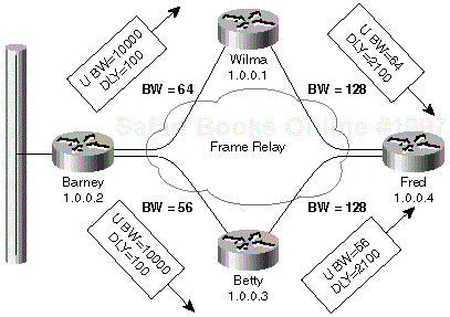
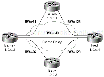
A simple example of vector metric propagation is shown in Figure 1-1 where the bandwidth on the Frame Relay links is configured as indicated in the figure and the delay on all interfaces has default values from Table 1-2.
When the Ethernet interface on router Barney becomes active, Barney announces the subnet configured on the Ethernet interface with 10 Mbps bandwidth and a delay of 100 microseconds. Wilma and Betty receive this update, add the delay of the incoming interface to the announced delay and minimize the bandwidth according to formulas in Equation 1-1. The new vector metric is announced further to router Fred that performs the same operation.
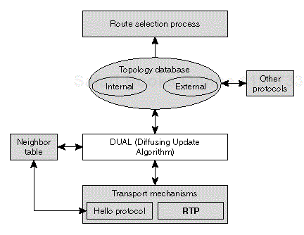
The central algorithm of EIGRP is the Diffusing Update Algorithm (DUAL) that relies on protocols (such as the hello protocol and the reliable transport protocol) and data structures (such as the neighbor table and the topology table) to provide all the routers in a network with consistent information leading to optimum route selection. Figure 1-2 relates DUAL to all these other components.
We start our exploration of DUAL with some terminology definitions, followed by a detailed look at the behavior of the DUAL algorithm in various scenarios, from adding a new route to losing a route or adjacency with a neighboring router.
Note
Throughout our discovery of EIGRP operation, we use extensive debugging capabilities built in Cisco IOS. I strongly urge readers who want to achieve an in-depth understanding of EIGRP operation to do the same in a lab environment. I also strongly discourage extensive use of EIGRP debugging (or any other debugging facility) in a production network.
Before discussing details of DUAL, it's beneficial to define a few terms that are used throughout the rest of this chapter. The best place to start is with the definition of upstream and downstream routers.
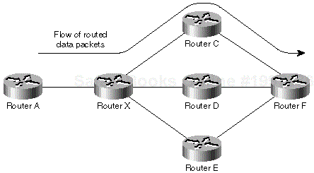
Imagine a network where the routed data toward a particular destination subnet flows from A toward F through X and C, as presented in Figure 1-3.
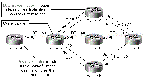
From the standpoint of router X, router C acts as a downstream router and router A acts as an upstream router. (Imagine the data flow as a river to get a better understanding of upstream/downstream concepts.) Figure 1-4 demonstrates the concept of upstream and downstream routers in the network displayed in Figure 1-3 from the perspective of router X.
Definition
The downstream router (for a subnet) is the router that is closer to the destination subnet and that the current router uses to forward data packets toward the destination subnet.
The upstream router (for a subnet) is a router that is further away from the destination subnet than the current router and that uses the current router to forward data packets toward the destination subnet.
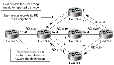
Each EIGRP router uses its topology table to select the best route toward each destination in the table. The vector metric of the best route is reported to the router's neighbors. The composite metric (or distance) of this route is called reported distance.
Definition
Reported distance is the distance reported to the current router from a neighbor.
Each router adds its interface metrics to the distance reported by its neighbor to get its own distance to the reported destination. The reported distance propagation in the network from Figure 1-4 is illustrated in Figure 1-5.
Note
Although the composite distances cannot be simply added together because the operation performed on the vector metric is not linear, we'll assume that we can add them to simplify the examples in this section.
The router on the lowest-cost path toward the destination becomes the successor for a particular subnet as shown in Figure 1-6. The successor for a subnet is also the downstream router for the same subnet.
Definition
The successor is the next-hop router for traffic from the current router toward the destination.
Sometimes an EIGRP neighbor does not become a successor, but it unambiguously does not use the current router as its successor. In these scenarios, the neighbor is a feasible successor, meaning it can become a successor if the route through the current successor is gone.
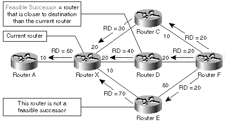
For example, router D in Figure 1-6 is not the successor of router X because the combined reported distance (40) and interface distance (20) is higher than the minimum distance of router X (50). It's also evidently not using router X as its successor because the reported distance of router D (40) is lower than the distance of router X (50).
Many possible ways of finding out whether a specific router is not an upstream router exist. EIGRP designers decided to use one of the most reliable (and most restrictive) ones:
A router is definitely not an upstream router if its reported distance is lower than the current best metric to a given destination. For a router to be an upstream router with a reported distance that is less than the current best metric, it must have a negative interface distance, which is impossible by design.
Definition
With this rule in mind, we can define several new terms:
The feasible successor is a router that is closer to the destination than the current router. A feasible successor is guaranteed not to be an upstream router of the current router.
A neighbor is a feasible successor if it meets feasibility condition
Feasibility distance is the minimum distance from the current router toward the destination since the last time a DUAL computation completed. A neighbor meets the feasibility condition if its reported distance is strictly lower than the feasibility distance.
A neighbor is a feasible successor if it meets the feasibility condition.
A feasible successor on the least-cost path is a successor. All these concepts are illustrated in Figure 1-7.
Router D is not a successor for router X because the distance of the path through router D is 60 (the reported distance of 40 plus the interface distance of 20). It is a feasible successor because its reported distance (40) is lower than the feasibility distance of router X (50) (or the best path router X has available, through router C). Router E is not a feasible successor because its reported distance (70) is greater than the feasibility distance of router X.
With all the EIGRP terms defined, you can start exploring the workings of DUAL. We'll start with the easiest operations (route addition and metric decrease) and work our way through more and more complex scenarios, finally arriving at a full diffusing computation. A test network of four routers is used for all examples. The routers are connected with Permanent Virtual Circuits (PVC) through a Frame Relay network. The PVCs (also called Data Link Connection Identifier or DLCI) have the Committed Information Rates (CIR) depicted in Figure 1-8.
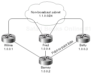
All DLCIs from Barney are configured on unnumbered point-to-point interfaces and the DLCIs between Betty, Fred, and Wilma are on a common partially meshed subnet, as shown in Figure 1-9.
When a new subnet becomes reachable through Barney, for example, with the commands in Example 1-5, Router Barney immediately informs all its neighbors about the new route, as shown in Example 1-6.
Example 1-5. Example 1-5 Insert a New Subnet in the Network by Configuring an IP Address on a Loopback Interface
Barney(config)#interface loopback 1
Barney(config-if)#ip address 1.0.0.5 255.255.255.255
Example 1-6. Example 1-6 New Connected Subnet—Router Informs Its Neighbors
Barney#debug eigrp packet update query reply
EIGRP Packets debugging is on
    (UPDATE, QUERY, REPLY)
Barney#debug eigrp fsm
EIGRP FSM Events/Actions debugging is on
Barney#
DUAL: dual_rcvupdate(): 1.0.0.5/32 via Connected metric 128256/0
DUAL: Find FS for dest 1.0.0.5/32. FD is 4294967295, RD is 4294967295 found
DUAL: RT installed 1.0.0.5/32 via 0.0.0.0
… Barney found out about the new route, it's time to inform its neighbors …
DUAL: Send update about 1.0.0.5/32. Reason: metric chg
DUAL: Send update about 1.0.0.5/32. Reason: new if
EIGRP: Enqueuing UPDATE on Serial0.1 iidbQ un/rely 0/1 serno 128-128
EIGRP: Enqueuing UPDATE on Serial1.1 iidbQ un/rely 0/1 serno 128-128
EIGRP: Enqueuing UPDATE on Serial2.1 iidbQ un/rely 0/1 serno 128-128
Each of Barney's neighbors (Wilma, Betty, and Fred) process the incoming updates from Barney and find that Barney has announced the best route toward the new subnet. Barney becomes their successor, as shown in Example 1-8.
Example 1-8. Example 1-8 Router Receives a New Route from Its Neighbor
Fred#
EIGRP: Received UPDATE on Serial0.1 nbr 1.0.0.2
  AS 1, Flags 0x0, Seq 255/134 idbQ 0/0 iidbQ un/rely 0/0
DUAL: dest(1.0.0.5/32) not active
DUAL: dual_rcvupdate(): 1.0.0.5/32 via 1.0.0.2 metric 53973248/128256
Barney's reported distance toward the destination subnet is 128256 when converted
into EIGRP composite metric. Fred's own composite metric of the direct path to Barney
through interface Serial 0.1 is 53973248, as seen from the last debugging line above.
DUAL: Find FS for dest 1.0.0.5/32. FD is 4294967295, RD is 4294967295
found
Fred's current feasibility distance for subnet 1.0.0.5 is infinity (4294967295),
which is also its reported distance. Obviously Barney offers a better route which
is immediately selected and installed.
DUAL: RT installed 1.0.0.5/32 via 1.0.0.2
After selecting the route offered by Barney, Fred has to inform its neighbors about the new route. Its updates to Wilma and Betty are obvious; it reports the metric through the best path it has to this new destination as its new reported distance, as shown in Example 1-9.
Example 1-9. Example 1-9 Fred Sends the Information about the New Best Route to Its Other Neighbors
Fred#
DUAL: Send update about 1.0.0.5/32. Reason: metric chg
DUAL: Send update about 1.0.0.5/32. Reason: new if
01:46:46: EIGRP: Enqueuing UPDATE on Serial0.1 nbr 1.0.0.2 iidbQ un/rely 0/0 peerQ
un/rely 0/0 serno 90-90
01:46:46: EIGRP: Enqueuing UPDATE on Serial0 nbr 1.1.0.1 iidbQ un/rely 0/0 peerQ un/
rely 0/0 serno 90-90
01:46:46: EIGRP: Enqueuing UPDATE on Serial0 nbr 1.1.0.3 iidbQ un/rely 0/0 peerQ un/
rely 0/0 serno 90-90
The real question is, what is Fred sending to Barney and why? The debugging outputs on Fred don't tell us what's going on and Barney is also silent about this update, so the only help is a packet analyzer, such as Sniffer, which tells us that Fred is sending Barney a poison update (a regular update with the delay set to infinity) to prevent any potential loops.
Our current knowledge of EIGRP can be formulated in a set of rules.
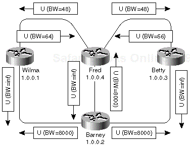
The first few steps in propagation of the new subnet as observed in the debugging printouts are also illustrated in Figure 1-10.
To understand the various bandwidth values in Figure 1-10, note the following:
After processing Barney's update, Fred receives two more updates: one from Wilma and one from Betty. They both offer Fred a better route than the route going directly through the Frame Relay link to Barney. Fred follows the same steps as before (see Example 1-10).
Example 1-10. Example 1-10 Router Fred Receives an Update from Router Betty
Fred#
EIGRP: Received UPDATE on Serial0 nbr 1.1.0.3
  AS 1, Flags 0x0, Seq 131/145 idbQ 0/0 iidbQ un/rely 0/0
DUAL: dest(1.0.0.5/32) not active
DUAL: dual_rcvupdate(): 1.0.0.5/32 via 1.1.0.3 metric 46866176/46354176
Fred received an update from Betty. Betty's reported distance is 46354176. Fred's distance composite metric for this path is 46354176 (see Example 1-11).
Example 1-11. Example 1-11 Router Fred Receives an Update from Betty—Continued
DUAL: Find FS for dest 1.0.0.5/32. FD is 53973248, RD is 53973248
DUAL:         1.0.0.2 metric 53973248/128256
DUAL:         1.1.0.3 metric 46866176/46354176 found Dmin is 46866176
The new route from Betty is compared with the route from Barney already in Fred's topology table. The new route has a lower distance (from Fred's perspective) and the successor for network 1.0.0.5 is changed. Fred has to inform its neighbors about the better route (see Example 1-12).
Example 1-12. Example 1-12 The Router Fred Selects the Better Route Offered by Router Betty
DUAL: RT installed 1.0.0.5/32 via 1.0.0.2
DUAL: RT installed 1.0.0.5/32 via 1.1.0.3
DUAL: Send update about 1.0.0.5/32. Reason: metric chg
DUAL: Send update about 1.0.0.5/32. Reason: new if
However, before the updates from Fred can be sent out, another update is received from Wilma, and it's even better (see Example 1-13).
Example 1-13. Example 1-13 Router Fred Receives an Update from Router Wilma
EIGRP: Received UPDATE on Serial0 nbr 1.1.0.1
  AS 1, Flags 0x0, Seq 86/146 idbQ 2/0 iidbQ un/rely 0/0
DUAL: dest(1.0.0.5/32) not active
DUAL: dual_rcvupdate(): 1.0.0.5/32 via 1.1.0.1 metric 41152000/40640000
DUAL: Find FS for dest 1.0.0.5/32. FD is 46866176, RD is 46866176
DUAL:       1.1.0.3 metric 46866176/46354176
DUAL:       1.1.0.1 metric 41152000/40640000
DUAL:       1.0.0.2 metric 53973248/128256 found Dmin is 41152000
Because the newly received route is selected as the best route, the distance of the route Fred is using decreases, so Fred has to propagate this lower reported distance to its neighbors (see Example 1-14).
Example 1-14. Example 1-14 New Best Route Selected and Propagated to Fred's Neighbors
DUAL: RT installed 1.0.0.5/32 via 1.1.0.3
DUAL: RT installed 1.0.0.5/32 via 1.1.0.1
DUAL: Send update about 1.0.0.5/32. Reason: metric chg
EIGRP: Enqueuing UPDATE on Serial0.1 nbr 1.0.0.2
EIGRP: Enqueuing UPDATE on Serial0 nbr 1.1.0.1
EIGRP: Enqueuing UPDATE on Serial0 nbr 1.1.0.3
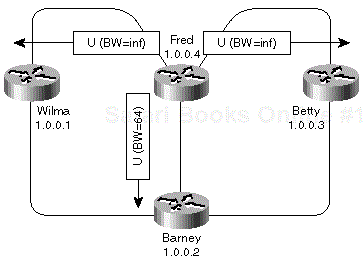
Fred sends a poison update to Wilma (DUAL Rule 2) and Betty (DUAL Rule 3, Betty is reachable through the same interface as Wilma), and a regular update to Barney (DUAL Rule 1). These updates are displayed in Figure 1-11.
Barney receives Fred's update, stores it in the topology table, and otherwise completely ignores it. The corresponding debugging printouts can be found in Example 1-15.
Example 1-15. Example 1-15 A Route Received That Is Not Better Than the One the Router Already Has
Barney#
EIGRP: Received UPDATE on Serial0.1 nbr 1.0.0.4
  AS 1, Flags 0x0, Seq 158/269 idbQ 0/0 iidbQ un/rely 0/0 DUAL: dest(1.0.0.5/32) not
   active
DUAL: dual_rcvupdate(): 1.0.0.5/32 via 1.0.0.4 metric 54997248/41152000
DUAL: Find FS for dest 1.0.0.5/32. FD is 128256, RD is 128256
DUAL: 0.0.0.0 metric 128256/0
DUAL: 1.0.0.4 metric 54997248/41152000 found Dmin is 128256
At the end of this data exchange, Fred has three routes toward 1.0.0.5 in its topology table. They are displayed in Example 1-16.
Example 1-16. Example 1-16 Final Topology Table Entries on Router Fred for Network 1.0.0.5/32
Fred#show ip eigrp topology 1.0.0.5 255.255.255.255
IP-EIGRP topology entry for 1.0.0.5/32
  State is Passive, Query origin flag is 1, 1 Successor(s), FD is 41152000
  Routing Descriptor Blocks:
  1.1.0.1 (Serial0), from 1.1.0.1, Send flag is 0x0
      Composite metric is (41152000/40640000), Route is Internal
      Vector metric:
        Minimum bandwidth is 64 Kbit
        Total delay is 45000 microseconds
        Reliability is 255/255
        Load is 1/255
        Minimum MTU is 1500
        Hop count is 2
  1.1.0.3 (Serial0), from 1.1.0.3, Send flag is 0x0
     Composite metric is (46866176/46354176), Route is Internal
     Vector metric:
        Minimum bandwidth is 56 Kbit
        Total delay is 45000 microseconds
        Reliability is 255/255
        Load is 1/255
        Minimum MTU is 1500
        Hop count is 2
  1.0.0.2 (Serial0.1), from 1.0.0.2, Send flag is 0x0
     Composite metric is (53973248/128256), Route is Internal
     Vector metric:
        Minimum bandwidth is 48 Kbit
        Total delay is 25000 microseconds
        Reliability is 255/255
        Load is 1/255
        Minimum MTU is 1500
        Hop count is 1
The DUAL algorithm covered so far can be summarized in the pseudocode shown in Example 1-17.
Example 1-17. Example 1-17 DUAL Behavior on Receiving Routes with Better Metrics
Receiving update packet:
  Install information in topology table
  If ReceivedUpdate is better or equal than the current best route then
    Select the new best route
    Send update packets to all neighbors
  Else
     ????
  End If
The previous section covered DUAL behavior only under favorable conditions; a new or a better route was received. The real power of DUAL lies, however, in handling unfavorable conditions—route loss or metric increase.
It turns out that the DUAL algorithm handles these conditions in a pretty straightforward way that can be summarized in the following extensions to the previous algorithm (see Example 1-18).
Example 1-18. Example 1-18 High-Level Overview of a DUAL Algorithm
Receiving update packet:
  Install information in the topology table
  If ReceivedUpdate is better or equal than the current best route then
    Select the new best route
    Send update packets to all neighbors
  Else
If ReceivedUpdate was not received from current successor then
    Store the information in topology table, ignore the update
    Else
      Try to find a better route
    End If
  End If
Before going into details, we have to answer the following questions:
Why should EIGRP try to find a better route every time the successor reports an increase in the route metric?
How does EIGRP indicate a route loss?
How does EIGRP handle other events such as a link failure or neighbor loss?
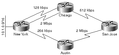
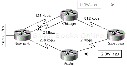
To answer the first question, consider the example in Figure 1-12, where a four-router network is implemented with leased lines of various speeds.
When the 2-Mbps line fails between Chicago and New York, the Chicago router could switch over to the 128-kbps line immediately and report the increased metric to the San Jose router. If the San Jose router accepts the increased metric without trying to find an alternate route, the result is suboptimal routing because the new best route toward New York really goes through Austin. It's therefore mandatory to look for an alternate route every time the successor reports an increased route metric.
The two previous questions listed at the top of this section, namely "How does EIGRP indicate a route loss?" and "How does EIGRP handle other events such as a link failure or neighbor loss?" are easier to answer:
EIGRP reports a route loss with a normal update packet by setting the delay portion of vector metric to infinity (–1).
EIGRP handles the loss of a directly connected subnet as an update packet with the delay set to infinity received from an external source in the router (loss of an external route that has been redistributed into EIGRP is handled in a similar fashion).
EIGRP handles link loss as the loss of a directly connected subnet plus a loss of one or more neighbors if there are EIGRP neighbors reachable through the lost interface.
EIGRP handles a neighbor loss as if it had received an update packet from that neighbor with delay set to infinity for every route received from that neighbor.
To illustrate these points, see what happens when router Fred in our test network (refer to Figure 1-12) loses its Frame Relay link (subnet 1.1.0.0/24).
Note
Only the relevant portions of debugging outputs are shown; detailed DUAL computation printouts are deleted for clarity reasons.
The following debugging options were used to generate the printouts (see Example 1-19).
Example 1-19. Example 1-19 EIGRP Debugging Is Enabled on Router Fred
Fred#show debug
EIGRP:
  EIGRP FSM Events/Actions debugging is on
  EIGRP Packets debugging is on
    (UPDATE, QUERY, REPLY)
Link loss is first handled as the loss of a directly connected subnet (see Example 1-20).
Example 1-20. Example 1-20 Interface Is Lost on Router Fred
DUAL: dual_rcvupdate(): 1.1.0.0/24 via Connected metric 4294967295/4294967295
DUAL: Find FS for dest 1.1.0.0/24. FD is 20512000, RD is 20512000
DUAL:   0.0.0.0 metric 4294967295/4294967295
DUAL:   1.0.0.2 metric 54869248/41024000 not found Dmin is 54869248
DUAL: Dest 1.1.0.0/24 entering active state.
Neighbor loss is forced for every neighbor reachable over that subnet. Every advertisement received from those neighbors is examined and deleted from the topology table. Additional processing is done if the neighbor was the successor for a particular route (see Example 1-21).
Example 1-21. Example 1-21 All the Neighbors Reachable Through the Lost Interface Are Lost
DUAL: linkdown(): start - 1.1.0.3 via Serial0.2
DUAL: Destination 1.0.0.1/32
DUAL: Removing dest 1.0.0.1/32, nexthop 1.1.0.3
DUAL: Best path rejected - forcing active
DUAL: Destination 1.1.0.0/24
DUAL: Clearing handle 2, count is now 2
DUAL: Destination 1.0.0.3/32
DUAL: Find FS for dest 1.0.0.3/32. FD is 20640000, RD is 20640000
DUAL:   1.1.0.3 metric 4294967295/4294967295
DUAL:   1.1.0.1 metric 47378176/46866176
DUAL:   1.0.0.2 metric 54485248/46354176 not found Dmin is 47378176
DUAL: Dest 1.0.0.3/32 entering active state.
DUAL: Set reply-status table. Count is 2.
DUAL: Not doing split horizon
DUAL: Destination 1.0.0.2/32
DUAL: Removing dest 1.0.0.2/32, nexthop 1.1.0.3
DUAL: Best path rejected - forcing active
DUAL: Destination 1.0.0.5/32
DUAL: Removing dest 1.0.0.5/32, nexthop 1.1.0.3
DUAL: Best path rejected - forcing active
DUAL: Destination 1.0.0.4/32
DUAL: linkdown(): finish
The same algorithm is repeated for every neighbor reachable over the lost subnet (see Example 1-22).
Example 1-22. Example 1-22 The Second Neighbor Reachable Through Serial 0.2 Is Also Lost
DUAL: linkdown(): start - 1.1.0.1 via Serial0.2
DUAL: Destination 1.0.0.1/32
DUAL: Removing dest 1.0.0.1/32, nexthop 1.1.0.1
DUAL: RT installed 1.0.0.1/32 via 1.0.0.2
DUAL: Destination 1.1.0.0/24
DUAL: Clearing handle 1, count is now 1
DUAL: Destination 1.0.0.3/32
DUAL: Clearing handle 1, count is now 1
DUAL: Destination 1.0.0.2/32
DUAL: Removing dest 1.0.0.2/32, nexthop 1.1.0.1
DUAL: RT installed 1.0.0.2/32 via 1.0.0.2
DUAL: Destination 1.0.0.5/32
DUAL: Removing dest 1.0.0.5/32, nexthop 1.1.0.1
DUAL: RT installed 1.0.0.5/32 via 1.0.0.2
DUAL: Destination 1.0.0.4/32
DUAL: linkdown(): finish
An EIGRP router faced with an increased metric from its successor can find a better route immediately if the new best route goes through a feasible successor. The action in this case is immediate; the new route is selected and updates are sent to all the neighbors to inform them of the change in the network topology. This is exactly what happens in our test network when Fred loses subnet 1.1.0.0/24; Barney is the feasible successor for network 1.0.0.2 and the best (well, the only remaining) route toward that network also goes through Barney. The corresponding debugging outputs are shown in Example 1-23.
Example 1-23. Example 1-23 Route Loss with a Feasible Successor Available in the Topology Table
Fred#debug ip eigrp 1 1.0.0.2 255.255.255.255
IP Target enabled on AS 1 for 1.0.0.2/32
IP-EIGRP AS Target Events debugging is on
Fred#show debug
IP routing:
  IP-EIGRP AS Target Events debugging is on
EIGRP:
  EIGRP FSM Events/Actions debugging is on
  EIGRP Packets debugging is on
    (UPDATE, QUERY, REPLY)
Fred#
DUAL: linkdown(): start - 1.1.0.3 via Serial0.2
DUAL: Destination 1.0.0.2/32
DUAL: Removing dest 1.0.0.2/32, nexthop 1.1.0.3
DUAL: Best path rejected - forcing active
DUAL: linkdown(): finish
DUAL: linkdown(): start - 1.1.0.1 via Serial0.2
DUAL: Destination 1.0.0.2/32
DUAL: Removing dest 1.0.0.2/32, nexthop 1.1.0.1
DUAL: RT installed 1.0.0.2/32 via 1.0.0.2
DUAL: linkdown(): finish
Note
The debugging printout changed between IOS versions 11.2 and 11.3T. IOS 11.2 prints the whole topology table indicating the best route selected, whereas IOS 11.3T informs you only that a new best route is installed. A sample IOS 11.2 printout is shown in Example 1-24.
Example 1-24. Example 1-24 Printout from Example 1-23 as Displayed under IOS 11.2
DUAL: linkdown(): start - 1.1.0.1 via Serial0.2
DUAL: Destination 1.0.0.2/32
DUAL: Find FS for dest 1.0.0.2/32. FD is 41152000, RD is 41152000
DUAL:   1.1.0.1 metric 4294967295/4294967295
DUAL:   1.0.0.2 metric 53973248/128256 found Dmin is 53973248
DUAL: Removing dest 1.0.0.2/32, nexthop 1.1.0.1
DUAL: RT installed 1.0.0.2/32 via 1.0.0.2
The switch over to the feasible successor is immediate and local to the router. The route stays passive (no diffusing computation exists for the route) and no other routers are involved. With this knowledge, we can write the first approximation of our algorithm to select alternate routes (see Example 1-25).
Example 1-25. Listing 1-25 DUAL Selection of Alternate Routes
Try to find a better route:
  Find the new best route in topology table
  IfNewBestRoute goes through a feasible successor then
    Select the NewBestRoute
    Send update packets to all neighbors
  Else
    Ask other neighbors about an alternate route
  End If
It's worth noting that EIGRP behavior might be random in some border cases. Assume that the internal order of neighbors in router Fred is different, and the linkdown events are processed in a different sequence. (The linkdown event for neighbor 1.1.0.1 is processed before the linkdown event for neighbor 1.1.0.3.) The route with the minimum reported distance for network 1.0.0.2/32 after the neighbor 1.1.0.1 is lost does not go through a feasible successor and router Fred starts a diffusing computation, as seen in Example 1-26.
Example 1-26. Listing 1-26 Alternate Route Loss Sequence—Best Route Is Not a Feasible Successor
Fred#
DUAL: linkdown(): start - 1.1.0.1 via Serial0.2
DUAL: Destination 1.0.0.2/32
DUAL: Find FS for dest 1.0.0.2/32. FD is 41152000, RD is 41152000
DUAL:   1.1.0.1 metric 4294967295/4294967295
DUAL:   1.0.0.2 metric 53973248/128256
DUAL:   1.1.0.3 metric 46866176/46354176 not found Dmin is 46866176
DUAL: Dest 1.0.0.2/32 entering active state.
DUAL: Set reply-status table. Count is 2.
DUAL: Not doing split horizon
DUAL: linkdown(): finish
Note
Although a router with a feasible successor can select an alternate route immediately, its upstream neighbors might not be so lucky—a fact often overlooked by EIGRP network designers. Consider the network in Figure 1-12. When the Chicago router loses its 2-Mbps link to New York, it already has a feasible successor and can switch over to a 128-kbps link immediately. However, when the Chicago router reports an increased route metric to the San Jose router, the San Jose router has no feasible successor and has to start a diffusing computation.
When an EIGRP router cannot find an alternate route (no alternate route exists, or the new best route still goes through the successor reporting increases in the route metric, or the new best route does not go through a feasible successor), it starts a diffusing computation by asking all its neighbors about an alternate route. A diffusing computation is performed in a series of steps:
The route in question is marked active in the topology table.
A reply-status table is created to track replies expected from the neighbors.
A query is sent to the neighbors.
Responses are collected from all the neighbors and stored in the topology table. The response status of individual neighbors is tracked in the reply-status table.
The best response is selected in the topology table and the new best route is installed in the routing table.
If necessary, an update is sent to the neighbors to inform them of the changed network topology.
The router starting the diffusing computation has already gone through several steps:
Its topology table reflects the changed state of the network. (It contains information about increased or infinite metric from a successor.)
The new (temporary) best route toward the destination is already selected in the topology table but it either goes through a successor reporting the change or through a neighbor that is not a feasible successor, so it cannot be used immediately.
The first few steps in the diffusing computation are performed in the router:
The route in the topology table is marked active. This flag serves to prevent query loops.
A timer is started to guarantee network convergence in a reasonable time.
The router creates a data structure to track responses from all neighbors involved in the diffused computation.
When all these preparatory steps are finished, the router sends a query packet to its neighbors. The query packet includes the new temporary best vector metric (or infinity if all the paths to a subnet were lost) to inform the neighbors about the topology change that triggered the diffusing computation.
In the test network, the bandwidth of a loopback interface on router Barney was changed from its default value to 16 kbps, forcing an EIGRP reconvergence for that particular route, as seen in the debugging printout in Example 1-27.
Example 1-27. Example 1-27 Router Initiates a Diffusing Computation
Barney#show debug
EIGRP:
  EIGRP FSM Events/Actions debugging is on
  EIGRP Packets debugging is on
    (UPDATE, QUERY, REPLY)
Barney#conf t
Enter configuration commands, one per line. End with CNTL/Z.
Barney(config)#interface loopback 1
Barney(config-if)#bandwidth 16
Barney(config-if)#
DUAL: dual_rcvupdate(): 1.0.0.5/32 via Connected metric 160128000/0
DUAL: Find FS for dest 1.0.0.5/32. FD is 5127936, RD is 5127936
DUAL:   0.0.0.0 metric 160128000/0
DUAL:   1.0.0.4 metric 54997248/41152000 not found Dmin is 54997248
DUAL: Dest 1.0.0.5/32 entering active state.
DUAL: Set reply-status table. Count is 3.
DUAL: Not doing split horizon
EIGRP: Enqueuing QUERY on Serial0.1 nbr 1.0.0.4 serno 91-91
EIGRP: Enqueuing QUERY on Serial1.1 nbr 1.0.0.3 serno 91-91
EIGRP: Enqueuing QUERY on Serial2.1 nbr 1.0.0.1 serno 91-91
Note
The debugging outputs in the section titled, "Simple DUAL Operation—Adding New Routes," in this chapter, are similar to the debugging output in Example 1-28. In both situations, we reduce three lines of debugging output into a single line that's most significant for DUAL discussions—the line that tells us which packet type was enqueued for which neighbor, as shown in Example 1-29.
Example 1-28. Example 1-28 The Actual EIGRP Debugging Printout upon Sending a Packet to an EIGRP Neighbor
EIGRP: Enqueuing QUERY on Serial1.1 iidbQ un/rely 0/1 serno 91-91
EIGRP: Enqueuing QUERY on Serial0.1 nbr 1.0.0.4 iidbQ un/rely 0/0 peerQ un/rely 0/
0 serno 91-91
EIGRP: Sending QUERY on Serial0.1 nbr 1.0.0.4
  AS 1, Flags 0x0, Seq 129/106 idbQ 0/0 iidbQ un/rely 0/0 peerQ un/rely 0/1 serno
  91-91
The router receiving a query packet uses the following rules to process the query:
If the router sending the query previously supplied topology information about the route being queried, the information in the query overwrites the information previously received from the neighbor sending the query.
If the router receives a query about a route that is not in its topology table, it immediately replies with an infinite metric and stops query processing. (If the router never received any information about the route from any neighbor, it makes no sense to further propagate the search for that route.)
If the route is already active (for example, the diffusing computation has encountered a query loop), the router replies with its current best path and stops query processing.
If the query is not received from a successor, the router replies with its current best route. The route stays passive, and the router completes its part of diffused computation.
If the query is received from the only successor and there is no other EIGRP neighbor, the router replies with infinite metric (stub router case).
The router selects the new best route toward the destination. If that route goes through a feasible successor, the router selects the alternate route (local computation) and reports the new best route to the query originator.
If no alternate route exists or the new best route still points to the router from which the query was received or the new best route does not go through a feasible successor then the router recursively propagates the query to its neighbors.
These rules are summarized in Table 1-4.
Table 1-4. Action Taken upon Receiving an EIGRP Query
|
Condition |
Action |
|---|---|
|
Route not in topology table |
Reply with infinity. |
|
Route already active |
Reply with current best metric (could be infinity). |
|
Query received from nonsuccessor |
Reply with current best route. |
|
Query received only from successor, no other EIGRP neighbors |
Reply with infinity. |
|
Query received from successor |
Select new best route. If it goes through a feasible successor, reply with new best route, otherwise extend diffused computation. |
Debugging outputs illustrating various scenarios are included in Example 1-30 through Example 1-33.
Example 1-30. Example 1-30 Query Received for a Route Not in the Topology Table
EIGRP: Received QUERY on Serial0.2 nbr 1.1.0.3
  AS 1, Flags 0x0, Seq 83/130 idbQ 0/0 iidbQ un/rely 0/0 peerQ un/rely 0/0
DUAL: dest(1.0.0.5/32) not active
DUAL: dual_rcvquery():1.0.0.5/32 via 1.1.0.3 metric 161152000/160640000,
RD is 4294967295
DUAL: Find FS for dest 1.0.0.5/32. FD is 4294967295, RD is 4294967295 found
DUAL: Send reply about 1.0.0.5/32 to 1.1.0.3
Example 1-31. Example 1-31 Query Received While the Route Is Active
EIGRP: Received QUERY on Serial0.1 nbr 1.0.0.4
  AS 1, Flags 0x0, Seq 110/129 idbQ 0/0 iidbQ un/rely 0/0
DUAL: dual_rcvquery():1.0.0.5/32 via 1.0.0.4 metric 161664000/161152000,
RD is 160128000
DUAL: Send reply about 1.0.0.5/32 to 1.0.0.4
EIGRP: Enqueuing REPLY on Serial0.1 nbr 1.0.0.4 iidbQ un/rely 0/1 peerQ un/rely
0/0 serno 92-92
Example 1-32. Example 1-32 Query Received from a Neighbor That Is Not the Current Successor
EIGRP: Received QUERY on Serial0.1 nbr 1.0.0.2
  AS 1, Flags 0x0, Seq 242/178 idbQ 0/0 iidbQ un/rely 0/0 peerQ un/rely 0/0
DUAL: dual_rcvquery():1.0.0.5/32 via 1.0.0.2 metric 160640000/160128000,
RD is 41152000
DUAL: Find FS for dest 1.0.0.5/32. FD is 41152000, RD is 41152000
DUAL:   1.1.0.1 metric 41152000/40640000
DUAL:   1.1.0.3 metric 46866176/46354176
DUAL:   1.0.0.2 metric 160640000/160128000 found Dmin is 41152000
DUAL: Send reply about 1.0.0.5/32 to 1.0.0.2
DUAL: RT installed 1.0.0.5/32 via 1.1.0.1
EIGRP: Enqueuing REPLY on Serial0.1 nbr 1.0.0.2 iidbQ un/rely 0/1 peerQ un/rely
0/0 serno 202-202
Example 1-33. Example 1-33 Query Received from the Successor, but There Is No Feasible Successor
DUAL: dual_rcvquery():1.0.0.5/32 via 1.1.0.1 metric 161152000/160640000,
RD is 41152000
DUAL: Find FS for dest 1.0.0.5/32. FD is 41152000, RD is 41152000
DUAL:   1.1.0.1 metric 161152000/160640000
DUAL:   1.1.0.3 metric 161152000/160640000
DUAL:   1.0.0.2 metric 160640000/160128000 not found Dmin is 160640000
DUAL: Dest 1.0.0.5/32 entering active state.
DUAL: Set reply-status table. Count is 3.
DUAL: Not doing split horizon
DUAL: Going from state 1 to state 3
EIGRP: Enqueuing QUERY on Serial0.2 nbr 1.1.0.1 serno 204-204
EIGRP: Enqueuing QUERY on Serial0.2 nbr 1.1.0.3 serno 204-204
EIGRP: Enqueuing QUERY on Serial0.1 nbr 1.0.0.2 serno 204-204
Whenever a router that initiated a query receives a reply from its neighbor, it stores the received data in its topology table and marks the appropriate entry in the reply table. When all the replies are received, one step in the diffusing EIGRP computation is finished, and the router has all the information it needs to select the new best route. If the router initiated the diffusing computation, the overall diffusing computation is complete; otherwise, the router reports its results to the neighbor it received the query from in a reply packet.
After the diffusing computation is complete, the router that initiated the computation has the best overall route known in its topology table, and it also uses the proper downstream router. The other routers involved in the diffusing computation might not know the optimum route yet, so the diffusing computation results must be distributed to those routers as well. This step takes place only if the new best route was supplied by one of the replying neighbors; otherwise, the neighbors already know the new best route because it was supplied in the original query, and the extra update step is unnecessary.
These last steps generate the debugging outputs in Example 1-34 and Example 1-35.
Example 1-34. Example 1-34 Reply Received from One of the Neighbors
Fred#debug eigrp packet update query reply
Fred#debug eigrp fsm

EIGRP: Received REPLY on Serial0.1 nbr 1.0.0.4
  AS 1, Flags 0x0, Seq 108/129 idbQ 0/0 iidbQ un/rely 0/0
DUAL: dual_rcvreply(): 1.0.0.5/32 via 1.0.0.4 metric 54997248/41152000
DUAL: Count is 3
DUAL: Clearing handle 2, count is now 2
Example 1-35. Example 1-35 The Diffused Computation Is Finished, and Reply and Update Packets Are Sent
Fred#debug eigrp packet update query reply
Fred#debug eigrp fsm

EIGRP: Received REPLY on Serial0.1 nbr 1.0.0.2
  AS 1, Flags 0x0, Seq 376/300 idbQ 0/0 iidbQ un/rely 0/0
DUAL: dual_rcvreply(): 1.0.0.5/32 via 1.0.0.2 metric 160640000/160128000
DUAL: Count is 1
DUAL: Clearing handle 0, count is now 0
DUAL: Freeing reply status table
DUAL: Find FS for dest 1.0.0.5/32. FD is 4294967295, RD is 161152000 found
DUAL: Send reply about 1.0.0.5/32 to 1.1.0.3
DUAL: RT installed 1.0.0.5/32 via 1.1.0.3
DUAL: RT installed 1.0.0.5/32 via 1.0.0.2
DUAL: RT installed 1.0.0.5/32 via 1.0.0.2
DUAL: Send update about 1.0.0.5/32. Reason: new if
DUAL: Going from state 3 to state 1
EIGRP: Enqueuing REPLY on Serial0.2 nbr 1.1.0.3 serno 299-299
EIGRP: Enqueuing UPDATE on Serial0.1 nbr 1.0.0.2 serno 300-300
EIGRP: Enqueuing UPDATE on Serial0.2 nbr 1.1.0.3 serno 300-300
EIGRP: Enqueuing UPDATE on Serial0.2 nbr 1.1.0.1 serno 300-300
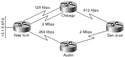
To further illustrate the details of a diffusing computation, the example network illustrated in Figure 1-13 is used. The network includes elements of the local diffusing computations as well as a diffusing computation triggered by an update packet.
Throughout these examples, assume that the delays on the links are equal (20 msec) and that the route selection is done purely on the basis of minimum end-to-end bandwidth.
The Chicago router has two entries for network 10.1.0.0/16 in its topology table—the best entry points to the 2-Mbps link into New York, and alternate entry points to the 128-kbps link. Both entries have a greater EIGRP distance than the entry in the New York router, which has a bandwidth of 10 Mbps. The New York router is thus both the successor and the feasible successor for the Chicago router.
When the 2-Mbps link between Chicago and New York fails and the successor for network 10.1.0.0/16 is lost, the Chicago router immediately selects the alternate route over a 128-kbps link because the new best route goes through a feasible successor. The Chicago router also informs the San Jose router about the reduced minimum bandwidth of the route. This first step is shown in Figure 1-14.
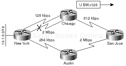
Figure 1-14. Figure 1-14. An Alternate Link between Chicago and New York Is Selected after a 2 Mbps Link Failure
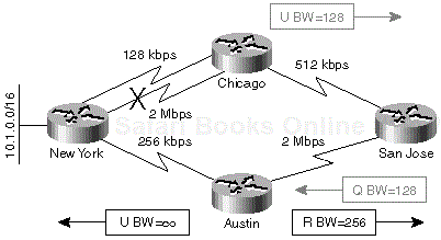
The San Jose router has only one entry for network 10.1.0.0/16 in its topology table, which is pointing toward the Chicago router. The reported bandwidth of that entry was 2 Mbps and San Jose's own bandwidth was 512 kbps. When the update is received from the Chicago router, San Jose's own cost is increased and the San Jose router tries to find an alternate route. It has no feasible successor, so it must start a diffusing computation and send the queries to all other neighbors (for example, Austin) as seen in Figure 1-15.
Note
Note that although the network design includes redundancy and feasible successors, a diffusing computation nonetheless begins. The presence of a feasible successor does not always guarantee that the convergence is immediate.
Another important fact is that the route from San Jose toward network 10.1.0.0/16 remains stable throughout the duration of the diffusing computation, pointing to the old downstream neighbor (Chicago). This guarantees that the traffic always reaches the destination network even during network convergence periods, although it might not always take the optimal path.
The topology table in the Austin router contained two entries for network 10.1.0.0/16: an entry pointing toward San Jose with a bandwidth of 512 kbps, and an alternate entry pointing toward New York with a bandwidth of 256 kbps. The New York router is also a feasible successor because its own EIGRP distance is less than the reported distance of the Austin router.
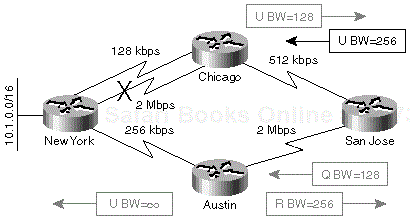
When the Austin router receives a query packet from the San Jose router, it stores the information from the query packet in its topology table. The old entry from the San Jose router is overwritten with the new information including the reduced minimum bandwidth. Because the query was received from the current successor, the Austin router needs to rerun DUAL to make certain it is using the optimum path. Luckily, Austin has a feasible successor for this destination (through the New York router) and therefore immediately selects this alternate path. The San Jose router is informed about the new best route via a reply packet and the New York router is informed about the change in network topology via a poison update packet. These packets are highlighted in Figure 1-16.
The San Jose router receives the reply packet from Austin and stores the received information in its topology table. It can also complete the diffusing computation because the Austin router was the only one queried. The topology table contains two entries: one from Chicago with a minimum bandwidth of 128 kbps, and another one from Austin with a minimum bandwidth of 256 kbps. The route through Austin is selected and installed in the routing table of the San Jose router.
As one of the last steps in the network convergence process, the San Jose router has to inform all other routers that it has changed the path it is using to this destination. An update is sent to the Chicago router listing the better bandwidth. The last step in network convergence is displayed in Figure 1-17.
A diffusing computation should be a transparent operation that runs behind the scenes, but we could make a similar statement about networks in general and we all know it's not always true. In reality, a large percentage of EIGRP problems and the majority of all EIGRP network meltdowns arise from failed diffusing computations— from too many computations being performed and too many routers being involved in the computation. Therefore, monitoring diffusing computations is crucial for successful EIGRP troubleshooting. You can monitor diffusing computations in your network in several ways:
Use EIGRP debugging commands. This approach is useful only in small networks (where you wouldn't expect any problems anyway) or when you are trying to troubleshoot events related to a particular route. Generic EIGRP debugging in large networks doesn't lead to good results.
Use the EIGRP event log in the router. The information in the event log is similar to information gathered with the debugging commands (although more cryptic) and requires extensive EIGRP knowledge to be properly understood. Therefore, using the EIGRP event log to try to understand the extent of diffused computation in your network is discouraged.
Use show ip eigrp topology and show ip eigrp neighbor commands. These commands give network operators or the troubleshooting engineers useful insight into the extent of a diffusing computation and the potential bottlenecks that could cause convergence problems.
Table 1-5 lists the commands that give you rapid insight into overall EIGRP performance while you are troubleshooting.
Table 1-5. Commands Used in Diffused Computation Monitoring
|
To Display… |
…Use the Following Command |
|---|---|
|
Routes currently under diffused computation |
show ip eigrp topology active |
|
Routes currently being converged |
show ip eigrp topology pending |
|
Whether this router is a potential bottleneck |
show ip eigrp neighbor detail |
The show ip eigrp topology active command displays all the routes for which a diffusing computation is being performed. This command identifies both the extent of diffusing computation (how many routes are currently active and how many routers are involved) as well as potential bottlenecks (routers that don't reply to queries) and convergence problems (long diffusing computation times). An example of a diffusing computation being identified with this command is shown in Example 1-36.
Example 1-36. Example 1-36 Monitoring Diffusing Computations with the show ip eigrp topology active Command
Fred#show ip eigrp topology active
IP-EIGRP Topology Table for process 1

Codes: P - Passive, A - Active, U - Update, Q - Query, R - Reply,
       r - Reply status

A 1.0.0.5/32, 1 successors, FD is 161152000, Q
    2 replies, active 00:00:02, query-origin: Successor Origin
         via 1.1.0.3 (161152000/160640000), r, Serial0.2, serno 323
         via 1.0.0.2 (160640000/160128000), Serial0.1, serno 327
    Remaining replies:
         via 1.1.0.1, r, Serial0.2
Potential EIGRP performance problems can be identified by the following symptoms:
Consistently high numbers of active routes indicate a constant source(s) of route flaps and network instabilities.
Long active times indicate slow overall network convergence and potential bottlenecks.
Long active times experienced while waiting for replies from a small number of neighbors indicate a communication bottleneck with those neighbors (on this router or on the neighbor router) or a communication problem beyond those neighbors.
Long active times experienced while waiting for replies from several neighbors indicate an interface bottleneck or a highly redundant topology.
Another useful command to help you identify whether the current router is a potential convergence bottleneck is show ip eigrp topology pending, which lists all active routes as well as those routes for which there are pending outgoing updates (see Example 1-37 for a sample printout).
Example 1-37. Example 1-37 Monitoring Network Convergence with the show ip eigrp topology pending Command
Fred#show ip eigrp topology pending
IP-EIGRP Topology Table for process 1

Codes: P - Passive, A - Active, U - Update, Q - Query, R - Reply,
       r - Reply status

P 1.0.0.5/32, 1 successors, FD is 46866176, U
         via 1.1.0.3 (46866176/46354176), Serial0.2, serno 329
         via 1.0.0.2 (53973248/10127872), Serial0.1, serno 327
If a particular router constantly displays several passive pending routes, that router definitely represents a bottleneck. To further verify whether the router under inspection represents the convergence bottleneck, you can use the show ip eigrp neighbor detail command to display all packets waiting to be sent from this router to its neighbors. This command can help you identify the link and the neighbor that's slowing down the convergence of the route in Example 1-37. As seen in Example 1-38, the only neighbor with an outstanding update packet is the neighbor 1.1.0.1, where the potential bottleneck lies.
Example 1-38. Example 1-38 Monitoring Potential Bottlenecks with the show ip eigrp neighbor detail Command
Fred#show ip eigrp neighbor detail
IP-EIGRP neighbors for process 1
H    Address              Interface    Hold Uptime   SRTT  RTO   Q   Seq
                                       (sec)         (ms)       Cnt  Num
2    1.1.0.3              Se0.2       172 02:13:17    16   5000  0   233
    Version 11.3/1.0, Retrans: 9, Retries: 0
1    1.1.0.1              Se0.2       121 02:13:35    49   5000  1   190
    Version 11.3/1.0, Retrans: 13, Retries: 0
     UPDATE seq 355 ser 334-334 Sent Sequenced
0    1.0.0.2              Se0.1        13 20:08:05    19   5000  0   418
    Version 11.3/1.0, Retrans: 1, Retries: 0
When the show ip eigrp neighbor detail command displays several packets in the Sequenced state, the bottleneck is the router under inspection. When the packets displayed by this command are in the Sent Sequenced state, the bottleneck is either the transmission media (which might be lossy) or the remote router (which is not acknowledging the packets in a timely manner). Interface-related bottlenecks are also easy to spot with the show ip eigrp interface command, where several pending routes indicate a transmission media bottleneck.
When you are designing a network, you have several options when faced with a high number of diffusing computations in an EIGRP network:
Reduce the number of route flaps in the network.
Reduce the diameter of diffusing computations.
Reduce the number of neighbors or the number of routers running EIGRP.
Increase the available EIGRP bandwidth between the neighbors.
All these measures are covered in detail in Part II and Part III of this book.
Diffusing computation rules, as discussed in the section entitled, "Diffusing Computation," in this chapter, require that a router receive replies from all the neighbors it queried before it can select the new best route. Under the following extreme circumstances, a neighbor might fail to respond to a query:
In the event of a neighbor failure, for example, a neighbor router reload that hasn't yet been noticed through the hello mechanism
In the event of a transmission media congestion or overload
In the event of software or hardware errors
In all these circumstances, the router originating the diffusing computation is blocked from completing the computation. To prevent these types of deadlock situations, EIGRP contains a built-in safety measure—a maximum time a diffusing computation can take. Whenever a diffusing computation takes longer than the timeout value, the diffusing computation is prematurely aborted; the adjacency with any nonresponding neighbors is cleared, and the computation proceeds as though these neighbors replied with an infinite metric. The route for which the computation is aborted is said to be stuck in active.
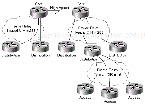
Stuck-in-Active (SIA) routes are a major source of EIGRP-related problems, especially because of their distributed nature. Consider the network in Figure 1-18.
Whenever there is a DLCI failure between the distribution and core layers, a core router starts a diffusing computation for all the routes previously reachable over the failed DLCI. Because the network does not contain any redundancy, there are no feasible successors and the diffusing computation spreads to all the remaining routers in the whole network including all the access routers. The link speed between distribution and access routers is very low; hence, there is a high probability that these links will be overloaded and become convergence bottlenecks. Unfortunately, the SIA event does not occur between the distribution and access routers; the first router to experience SIA timeout is most likely to be the core router initiating the diffusing computation. This router tries to recover from SIAs by clearing the adjacency with the router that timed out (in its perspective), namely the other core router. The net result of this action is network partitioning, the loss of several routes resulting in even more diffused computations, and probably more SIA events between other routers in this network. The end result of this chain of events can be a network meltdown resulting in several minutes of complete network outage.
It is clear from the previous example that the SIA event should be avoided if at all possible by the use of several available design and configuration techniques. Most techniques try to avoid or prevent the original reasons for an SIA event, but one technique tries to prevent the resulting catastrophe without removing the original causes—the extension of the stuck-in-active timer.
The default Stuck-in-Active timeout is three minutes, which should be enough for all properly designed networks. You can extend the timeout during a troubleshooting session if necessary, but you should consider this to be only a temporary measure that prevents network meltdowns. If when troubleshooting, you use this stopgap measure, you must adjust the timeout on all EIGRP speaking routers in the network (see Table 1-6).
Table 1-6. Changing the SIA Timeout
|
Task |
Command |
|---|---|
|
Change the Stuck-in-Active timeout |
router eigrp <AS> timers active-time <timeout-in-minutes> |
|
Disable the Stuck-in-Active check |
router eigrp <AS> timers active-time disabled |
SIA events are usually caused by several route flaps (or the loss of many routes) combined with slow-speed or lossy links in large networks. The usual causes can be categorized along these lines:
Flapping interface—. A single constantly flapping interface can introduce a constant stream of diffusing computations in the network; every time the interface goes down, all the routers in the network have to agree that there is no alternate route to the lost subnet. Over a period of time the number of outstanding queries can grow to the extent that one of the diffusing computations exceeds the SIA timeout.
Configuration change—. EIGRP-related configuration changes normally clear the adjacency between the router on which the changes were made and its neighbors (see the section titled, "Adjacency Resets—Causes and Consequences," in Chapter 2, "Advanced EIGRP Concepts, Data Structures, and Protocols" for more details), potentially resulting in several lost routes and diffusing computations. These can lead to SIA events in combination with slow-speed links as illustrated in the example network.
Lossy links—. EIGRP packets might get lost on lossy links resulting in retransmissions that might in turn lead to an extended convergence period when combined with several diffusing computations (caused by, for example, flapping interfaces or configuration changes).
Heavily loaded links—. Heavily loaded links usually experience packet drops that can cause EIGRP retransmissions finally resulting in SIA routes (see also lossy links).
Misconfiguration of the bandwidth parameter—. Recent EIGRP implementations try to prevent WAN link overload by pacing EIGRP data packets based on configured interface bandwidth. Misconfiguring the bandwidth on an interface can lead to packet loss or extremely low throughout; both of which can slow down the transmission of query and reply packets, thus increasing the overall time required to complete a diffusing computation.
Old EIGRP code—. Old EIGRP implementation (up to IOS versions 10.3(11) and 11.0(8)) as well as early maintenance releases of some IOS versions (for example, early IOS 11.2) contain several EIGRP-related software defects that can result in delayed retransmissions, lost packets, and finally, SIA events. The obvious remedy in this scenario is an IOS upgrade.
Routing loops with multiple (E)IGRP processes—. Blind two-way redistribution between multiple IGRP and/or EIGRP processes can lead to redistribution loops that trigger repetitive diffusing computations in all involved EIGRP processes (see also lossy links and flapping interface for more details).
Redistributed IGRP routes—. Automatic IGRP to EIGRP redistribution performed whenever IGRP and EIGRP are using the same AS number can lead to complex two-way multipoint redistribution scenarios that could cause routing loops (see also routing loops). More details can be found in Chapter 9, "Integrating EIGRP with Other Enterprise Routing Protocols."
Frame-Relay—. Several SIA-related configuration problems are usually encountered in Frame-Relay environments: flapping interfaces, lossy or heavily loaded links, and misconfigured bandwidth parameters. See Chapter 12, "Switched WAN Networks and Their Impact on EIGRP" and Chapter 13, "Running EIGRP over WAN Networks" for more details.
EIGRP is a modern routing protocol that combines simplicity and filtering capabilities of the distance-vector routing protocols such as Routing Information Protocol (RIP) or Interior Gateway Routing Protocol (IGRP) with fast convergence of link-state routing protocols such as Open Shortest Path First (OSPF) protocol. EIGRP is also the only routing protocol that supports all three layer-3 protocols most commonly found in enterprise networks: IP, IPX, and AppleTalk.
Configuring EIGRP in a small network is easy and does not require any network design. Therefore, EIGRP is the routing protocol of choice in most networks that do not require multivendor interoperability. An EIGRP network where no real network design was done can grow to a fairly large size without problems, but might also unexpectedly collapse when the number of routers or the number of changes per time unit exceeds a certain hard-to-specify limit. On the other hand, everyone designing and implementing a network based on a link-state routing protocol, such as OSPF, becomes aware of the need to implement network segregation with areas early on in the network growth cycle. The net result is that fewer large OSPF or IS-IS networks experience unexpected outages, but this result is not strictly technology-related. Remember, although EIGRP has the ability to cope with more abuse than link-state protocols, it can also break without warning when it cannot take any more.
Note
I've seen several large EIGRP networks that experienced fairly frequent outages and meltdowns, most of which were the result of missing design elements and improper implementation. I, therefore, strongly urge the reader to do a proper network design even though EIGRP does not require it in early stages when the network is still small. I also recommend using as many scalability features discussed in Part II of this book as possible to make your network as scalable and as stable as possible.
