
About this document
This information is intended to facilitate the deployment of IBM© FlashSystem© for the Epic Corporation electronic health record (EHR) solution by describing the requirements and specifications for configuring IBM FlashSystem 9500 and its parameters.
This document also describes the required steps to configure the server that hosts the EHR application. To complete these tasks, you must be knowledgeable of IBM FlashSystem 9500 and Epic applications.
|
Note: The information in this document is distributed on an “as is” basis, without any warranty that is either expressed or implied. Support assistance for the use of this material is limited to situations where IBM FlashSystem storage devices are supported and entitled, and where the issues are not specific to a blueprint implementation.
|
Executive summary
Data is flowing into healthcare systems at an unprecedented rate. Between EHRs, digitized diagnostics, and wearable medical devices, it is estimated that the average person leaves more than 1 million gigabytes of health-related data in their lifetime.1
All this new data creates tremendous potential for healthcare organizations to understand their patients better, and to provide them with more personalized, evidence-based care. At the same time, managing this tidal wave of data can be a serious challenge for organizations that are not adequately prepared. Adopting next-generation healthcare IT solutions today is the first step toward making the most of this new healthcare data, while also setting the stage to pursue cognitive healthcare in the future.
EHRs are one area where managing exponential data growth is key. EHRs give providers rapid access to patient data when and where they need it, but only if they are supported by an effective data storage solution.
To help healthcare organizations achieve continuous access to EHR data, IBM works closely with Epic, a leading provider of EHR solutions to ensure that IBM Flash Storage offerings can easily support current and anticipated Epic workload requirements.
By testing IBM storage systems with the Epic EHR platform, IBM can offer proven solutions to the customers of the two firms, which helps them reduce risk, accelerate decisions and actions, improve patient care, and overcome the challenge of massive data growth.
Scope
This Blueprint provides the following information:
•A solutions architecture and the related solution configuration information for the following essential components of software and hardware:
– IBM FlashSystem 9500
– Lenovo SR650 server, IBM Power8, or IBM Power9
– InterSystems Caché
– Epic Software Suite
•Detailed technical configuration steps for configuring IBM FlashSystem 9500
•Server configuration details for Caché database and Epic applications
This Blueprint does not:
•Provide performance analysis from a user perspective
•Replace any official manuals and documents that are issued by IBM
•Explain the installation and configuration of Caché and Epic applications
Prerequisites
This Blueprint assumes that the reader has basic knowledge of the following topics:
•Caché
•Epic applications
•Intel x86 and Red Hat Enterprise Linux (RHEL) tuning
•IBM Power and IBM AIX© tuning
•IBM FlashSystem all-flash storage arrays
Getting started: The Epic EHR solution with IBM FlashSystem 9500
This section describes the Epic implementation of EHRs, and the components that are part of the solution.
Epic
The integrated EHR software from Epic covers all aspects of healthcare operations, including patient engagement, clinical trials, specialties, distance care, mobile access, managed care, billing and revenue, interoperability, and government regulations, in addition to patient record access.
Epic software implementations use the following two main database technologies:
•Operational database: The online transaction processing (OLTP) database runs Caché from InterSystems Corporation as the main database engine.
•Analytical database: The analytical databases typically run on Microsoft SQL Server or Oracle database software.
Although the analytical database component features the highest bandwidth, the Caché (operational database) performance is by far the most critical aspect to the user experience and consequently, is where most of the attention on storage performance is focused.
InterSystems Caché
To better understand the Epic environment, the underlying database system that is used by Epic must be examined because Caché interfaces directly with the IBM hardware. Virtually the entire Epic environment relies on Caché to accomplish its work.
The Caché database engine is based on a B-Tree data storage structure. Internal to Caché, the user data is managed as 8 KB blocks.
Caché maintains a global buffer cache in the computer’s real memory. All transactions (read and write) between the user and the database are read in or written from the global buffer. The global buffer acts as a storage cache, which reduces operating system-level I/O requests. It also acts as a global data locking communication system that provides mutually exclusive access to data that is being referenced or changed by multiple users.
Data that is referenced by one or more users is initially read from the storage device (disk) into the global buffer. The data objects are now accessible for repeated operations, including updates to the contents. Access and updates occur rapidly because the data is kept in RAM.
As data blocks in the global buffer are updated, they are considered “dirty.” Caché flushes the dirty blocks at a regularly scheduled interval of about 80 seconds, or when the percentage of dirty blocks in the total global buffer exceeds the internal threshold, whichever comes sooner. Caché includes dedicated write daemon processes that perform the actual update operations. The flush of the dirty blocks is typically referred to as a write daemon cycle.
Caché uses a two-phase update technique for database updates. In the first phase (during the write daemon cycle), updates are first written to the CACHE.WIJ file (WIJ). The updates to the database file occur only after the WIJ updates completed successfully as part of the second phase. After all database updates are committed, Caché marks the WIJ as “clean.” The first WIJ writes are sequential writes of 256 KB blocks.
When the global buffer is not being flushed, the I/O requests that are issued by Caché are strictly read-only in nature. These I/O requests do not include the Caché Journal File, a time-sequenced log of database changes, which is being written out to disk sequentially. Writing to the Journal File is a continuous process, but does not require many resources. Therefore, the random read operations can occur with little or no interference.
This is not the case during the flush or write burst that is started every 80 seconds. While Caché continues to issue 100 percent read requests, the database engine also generates a large quantity of write requests in a short time.
Epic has strict read latency guidelines to avoid degrading user performance. Write latencies also become increasingly important for high-end scalability. For large implementations, this issue can lead to a clear conflict between optimal read performance and optimal write performance during intense write bursts.
IBM FlashSystem 9500
For decades, IBM offered a range of high-performance, ultra-low latency storage solutions. Now, IBM FlashSystem 9500 combines the performance of flash and NVM Express (NVMe) with the reliability and innovation of IBM FlashCore technology and the rich feature set of IBM Spectrum© Virtualize in one powerful new storage platform that provides the following benefits:
•The option to use industry-standard NVMe flash drives or new third-generation IBM FlashCore modules (FCMs) with the line-speed internal performance, multi-dimensional data protection, and innovative flash management features that are provided by IBM FlashCore technology
•The software-defined storage functions of IBM Spectrum Virtualize, which enables a full range of industry-leading data services, such as dynamic tiering, IBM FlashCopy© management, data mobility, and high-performance data encryption, among many others
•SCSI UNMAP support and all the thin provisioning, copy management, and efficiency features that customers expect from IBM Spectrum Virtualize-based storage
IBM FlashSystem 9500 delivers new levels of storage density in an efficient four-rack-unit (4U) chassis. A key innovation involves the transformation of IBM FlashCore technology into a standard 2.5-inch solid-state disk (SSD) form factor with NVMe interfaces so that 48 IBM FCMs can form the basis of the storage array. IBM FlashCore technology refers to the IBM innovations that enable IBM FlashSystem solutions to deliver consistent microsecond latency, extreme reliability, and a wide range of operational and cost efficiencies.
IBM FlashCore innovations include a hardware-accelerated nonvolatile memory (NVM) architecture and advanced flash management features, such as IBM Variable Stripe RAID technology, IBM-engineered error-correction codes, and proprietary garbage-collection algorithms that increase flash endurance and accelerate performance while reducing latency.
IBM FlashSystem 9500 systems use the powerful inline, hardware-accelerated data compression technology that provides consistent, high-performance data reduction across the full range of workloads.
The IBM FCMs are Federal Information Processing Standards (FIPS) 140-3 Level 1 certified, with cryptographic erase. Key management can be performed by using USB keys, or a key server for centralized key management.
Flexibility is built into the IBM FlashSystem 9500 architecture. Customers can choose IBM FCMs in many capacities, or opt for industry-standard NVMe-enabled flash drives. The IBM FCMs can be complemented with Storage Class Memory (SCM) NVMe drive technology. SCM technology offers even lower latency and when combined with FCM drives, can be used for even more demanding workloads.
Therefore, with the always-on, in-line, high-performance data compression that is provided by the IBM FCMs, effective capacities are over 4500 TB in a single 4U enclosure with a throughput of up to 100 GBps.
Data availability is of crucial importance for business. Any downtime causes immediate impact, including loss of customer loyalty and financial costs. IBM FlashSystem 9500 systems with current software deliver six 9s (99.9999%) data availability. These systems include no single point of failure, enterprise-proven control software, and the ability to perform maintenance concurrently with I/O. In addition, cloud-based IBM Storage Insights detects configuration errors to further improve availability.
Distributed RAID 6 (DRAID6) helps rebuild data faster if a disk failure occurs by striping the data, parity, and spare capacity across the disks.
Typical Epic configuration
Epic uses the following fundamental architecture models:
•Single Symmetric Multiprocessing (SMP)
The single database server architecture provides the greatest ease of administration.
• Enterprise Cache Protocol (ECP)
This tiered architecture retains a central database server with a single data storage repository. Unlike the SMP architecture, most processing needs are offloaded to application servers. The application servers contain no permanent data. This architecture offers increased scaling over the SMP architecture.
Many Epic customers use SMP architecture. Each architecture has a production database server that is clustered in an active-passive configuration to a failover server.
Figure 1 shows a high-level configuration of various components of the Epic solution that is built by using IBM FlashSystem 9500.

Figure 1 High-level configuration of Epic solution components
Epic storage configuration
The following practices are recommended for the basic storage configuration of the Epic production database:
•The database files must be isolated from the journal files and cannot coexist under the same controller. For recoverability purposes, it is important that an updated copy of the production journal files be available on a second controller that is outside the production array.
•Use an even number of virtual disks (VDisks) for operational and analytical data.
•Use a distributed RAID 6 configuration with all flash drives for the operational and analytical databases.
• Create 24 VDisks to be presented to the server for each Caché instance. This presentation must be verified to ensure that the volumes are equally spread across both node canisters within an I/O group.
Recommendations for FlashCopy configuration
The following practices are recommended for a FlashCopy configuration of Epic production database volumes:
•Correct sizing of the overall cache requirements must include related copy services requirements. At the time of FlashCopy resynchronization, FlashCopy also uses IBM FlashSystem 9500 write cache. Therefore, it is important to consider that use for the overall cache sizing (to include cache for the front-end application I/O, plus any extra cache for the back-end FlashCopy services).
• If you use storage copy services to facilitate backups, use two pools (managed disk groups), one for the source volume of the FlashCopy relationship and another for the target of the FlashCopy relationship.
•The FlashCopy target volumes must be created with the same size of production volumes.
•The ownership of FlashCopy target volumes must be the same as that of the FlashCopy source volumes.
The FlashCopy mappings or relationships must be configured with the incremental option set to On to allow the FlashCopy mapping to record the changes from the previous FlashCopy on the same mapping. This setting allows the FlashCopy background copy function to copy only the changes from the previous FlashCopy operation.
Consider the following points:
•It is recommended to set the FlashCopy grain size to 64 KB.
•In a FlashCopy relationship with the incremental option turned on, it is important to note the background copy rate along with the timing when issuing a FlashCopy operation. A higher background copy rate increases the speed of synchronization of FlashCopy volumes.
•The incremental FlashCopy target must follow the same rules as the production database to use the maximum available cache. At the time of FlashCopy resynchronization, FlashCopy also uses the write cache. Therefore, this issue is important to consider when determining the overall IBM FlashSystem 9500 cache sizing. Include cache for the front-end Epic application I/O, and extra cache for the back-end FlashCopy services.
•When FlashCopy is used to create a backup, it is essential to configure FlashCopy to be incremental, and to tune the background copy rate from a default value of 50 to a value that enables the background copy to finish in time without affecting production performance during the backup window.
•The recommendation is to set the background copy rate 70 - 80, where the FlashCopy operation is run approximately every 8 hours. This setting often provides the optimal balance between FlashCopy copy time and production I/O time when running with incremental FlashCopy operations.
•It is important to understand the relationship between the IOPS performance, background copy rate, and the frequency of FlashCopy operations. The more frequent the FlashCopy operations, the fewer data changes must be applied; therefore, the quicker the synchronization with an average background copy rate.
The fewer changes that are made reduces the effect of background copying and latency for production I/O. Therefore, consider the following important variables for configuring FlashCopy services:
– Number of IOPS
– Background copy rate
– Time between two FlashCopy operations
It is important to balance all these three variables to arrive at the best possible configuration for a balanced Caché workload, depending on the IOPS requirement.
Recommendations for Lenovo SR650 or Power8/Power9 server configuration
The following server recommendations for optimal configuration of databases are general and might vary from platform to platform and operating system-to-operating system:
•It is recommended to configure the native or IBM pcmpath multipath driver on the host.
•The queue depth of each physical disk must be configured to 64, or as little as 16 (if more total storage volumes are used). Also, each volume must have reserve policy set to No and round robin, for optimal performance.
•A single logical volume group must be created by using all 24 logical unit numbers (LUNs) that are mapped on the host.
•Eight logical volumes must be created, each using 12% of the space of the volume group. By using those logical volumes. eight file systems for production data also must be created.
•The remaining 4% can be used for the ninth logical volume, which is used for write image journaling. By using this ninth logical volume, a file system for write image journaling must be created.
•The logical volumes must be configured in a striped mode to enable uniform I/O distribution.
Lab validation
This section provides details about the simulated lab environment for configuring Epic with IBM FlashSystem 9500. This lab environment was used to validate the information that pertains to the best practices recommendations that were previously described.
The test system included the following components:
•IBM FlashSystem 9500 storage system
•A total of 24 IBM FCMs
•One Lenovo SR650 (32 processors, 180 GB, four 16 Gbps Fibre Channel ports, RHEL 8.5) server
•32-Gb Brocade Fibre Channel switches
Next, we describe the process to configure the storage and server to be used by the Caché database and Epic applications.
Storage configuration
The IBM FlashSystem 9500 features dual controller canisters and power supplies, and redundant cooling. FlashSystem 9500 uses four Intel Ice Lake CPUs per controller canister, which uses 24 cores per CPU.
Up to 3072 GB of memory can be configured per controller so that a single 4U storage array can use the performance and efficiency of up to 3 TBs of memory and multiple petabytes of storage (all moving at NVMe speeds) to handle even the most demanding real-time analytics or cognitive application workloads.
This section describes the steps to configure IBM FlashSystem 9500 and the RHEL server for a Caché database.
|
Note: For convenience, accuracy, and set up time savings, all of the tasks that are shown in Figure 2 - Figure 17 on page 17 and Figure 21 on page 20 - Figure 23 on page 20 are described in “Appendix B: FS9500 configuration by using CLI” on page 26. Then, they can be pasted into an SSH session and run to set up IBM FlashSystem 9500 in a matter of seconds.
|
Complete the following steps:
1. Open the IBM FlashSystem 9500 web console management interface by using the system’s hostname or IP address.
2. Click Monitoring → System and then, click Drive. The details of the drives are shown in the right window (see Figure 2).

Figure 2 Drive details
3. To create a pool, click Pools in the left window and then, click Pools → Create, as shown in Figure 3.

Figure 3 Creating a pool

Figure 4 Assigning the name of a new pool
The pool is created. Notice the command that was used while creating a pool, mkmkdiskgrp, as shown in Figure 5.

Figure 5 The mkmkdiskgrp command
The new pool and its details are listed in the Pools list, as shown in Figure 6. At this point, no storage is allocated to it.

Figure 6 Pool details before storage allocation
5. Select the pool and then, right-click or click Actions. Select Add Storage, as shown in Figure 7.

Figure 7 Adding storage
6. Administrators can use the quick preset configuration or an advanced method in which they can customize the pool. For the advanced option, select Advanced, as shown in Figure 8.

Figure 8 Customizing pool configuration by using the IBM FlashSystem interface
7. You can select the drive class, RAID type, number of flash drives, and other parameters, as shown in Figure 9. Select DRAID 6 and keep the default settings for the rest of the populated values. Click Assign to create the array.

Figure 9 Dive assignment
The DRAID 6 array is created and added to the pool, as shown in Figure 10.

Figure 10 Creating the DRAID 6 array by using the mkdistributearray command
The total capacity of the pool, and its available capacity, are displayed, as shown in Figure 11.

Figure 11 Pool details
8. It is recommended to use 24 volumes for Epic. To create a database of 60 TB, each volume is 2.5 TB (2,560 GB). For this example, 24 volumes are created by using the command-line interface (CLI), as shown in Figure 12. For more information about the command, “Appendix B: FS9500 configuration by using CLI” on page 26.
Figure 12 Creating volumes by using the CLI
The volumes are created, as shown in Figure 13.

Figure 13 List of newly created volumes
9. The volumes must be mapped to the server where the application runs. Click Volumes and select all of the volumes; then, right-click and select Map to Host or Host Cluster, as shown in Figure 14.

Figure 14 Mapping the host

Figure 15 Selecting the host

Figure 16 Host mapping summary

Figure 17 Host mapping command
Server configuration
The volumes that are mapped to a server can be listed by using the multipath command, as shown in Figure 18.

Figure 18 Disks on hosts
A total of 16 paths to each volume exit: eight preferred paths, and eight alternatives. The output of the multipath command for a single volume is shown in Figure 19.

Figure 19 Volume paths
To configure the server, complete the following steps:
1. On the host, create 24 physical volumes, a volume group, eight logical volumes, and eight file systems by using the script that is shown in Figure 20.

Figure 20 Creating file systems
2. Edit /etc/fstab to create entries for the file systems that were created. The Caché database can now be created on these file systems.
FlashCopy configuration
For FlashCopy, Epic recommends the use of fully allocated target volumes. Complete the following steps:
1. Create volumes on IBM FlashSystem 9500 for the FlashCopy target volumes, as shown in Figure 21. For more information about the command that is used to create these volumes, see “Appendix B: FS9500 configuration by using CLI” on page 26.
Figure 21 Creating volumes for FlashCopy volumes
2. Create the FlashCopy consistency group, as shown in Figure 22. For more information about the command that is used to create this group, see “Appendix B: FS9500 configuration by using CLI” on page 26.
Figure 22 Creating volumes for FlashCopy consistency group
3. Create incremental FlashCopy mappings by using the command that is shown in Figure 23. For more information about the command that is used to create these mappings, see “Appendix B: FS9500 configuration by using CLI” on page 26.
Figure 23 Creating FlashCopy mappings
For subsequent FlashCopy mappings, run the command that is shown in Figure 24.
Figure 24 Issuing FlashCopy mapping command
After the mappings are created and the background copy is complete, the user can follow this typical procedure before creating the FlashCopy image:
1. Freeze or quiesce the Caché database.
2. Freeze the file systems.
3. Create the FlashCopy image.
4. Unfreeze the file systems.
5. Unfreeze or unquiesce the Caché database.
Compression and savings
IBM FCMs feature built-in hardware compression; therefore, all data that is written to the disk is compressed by default.
The following steps show the benefits of the use of this compression feature:
1. Click Monitoring → System in the web console and then, click Drive. Notice that the details of the drives are shown in the right window (see Figure 25). In this example, the usable capacity of each drive is displayed.

Figure 25 IBM FlashCore FCMs
2. Click Pools → Internal Storage to see the details of the IBM FCMs (logical capacity and physical capacity are listed), as shown in Figure 26.

Figure 26 IBM FCM drive details
3. While creating the pool, the GUI shows the total capacity that is available by using IBM FCMs, as shown in Figure 27.

Figure 27 Total capacity available by using IBM FCMs
Figure 28 shows the pool details after the MDisk is added. Although the (physical) total capacity is 178.62 TiB, the post-compression capacity of the MDisk that is added to the pool is 77.68 TiB.

Figure 28 Pool storage capacity details
After creating 24 volumes (totaling 60 TiB), the space consumption of the pool is 27.94 TiB, as shown in Figure 29.

Figure 29 Pool consumption
On the dashboard of the web console (see Figure 30), a summary of storage space consumption and data compression is shown.

Figure 30 Consumption summary
4. Click the View Compression Details link shown in Figure 30 on page 22. The details of the drive compression and savings are show (see Figure 31).
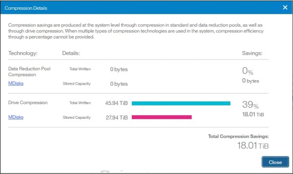
Figure 31 Compression details
After creating the fully allocated FlashCopy mappings, a summary of capacity consumption and savings from compression is shown (see Figure 32).

Figure 32 Storage consumption summary
The savings that are achieved after FlashCopy is used also are available) see Figure 33).

Figure 33 Savings results
Summary
For more than 10 years, IBM collaborated with Epic to help healthcare organizations optimize their IT environments.
IBM flash storage solutions deliver the performance, scalability, simplicity, and flexibility that are needed to take advantage of how hospitals and other clinical institutes store, access, secure, manage, share, and analyze data.
With IBM Spectrum Virtualize for enterprise functions and flash-based NVMe drives for security and performance, IBM FlashSystem 9500 is a powerful platform for demanding EHRs.
More information
For more information, see the following resources:
•IBM Data Storage for Healthcare:
•IBM Epic Alliance Team:
•Epic:
Appendix A: Epic hardware platform sizing process
Before an Epic solution deployment, Epic dedicates considerable resources to analyzing and understanding the customer’s specific requirements. To complete this process, a great deal of knowledge about the customer’s hospital, clinic, or health care environment, and knowledge about the Epic software, is needed. IBM does not have access to the information that Epic collects from its customers before software implementation; therefore, IBM cannot provide customers with initial sizing estimates for Epic implementations.
Epic provides each customer with a sizing document that outlines reasonably specific suggestions regarding the size of server and storage recommended. Next, the IBM account team works with the Epic customer to further refine the exact set of hardware that is required to implement Epic in production. Alterations in the configuration might be required based on several factors, including a customer’s IT implementation, equipment location, and cost considerations.
IBM strongly advises that you provision at least the Epic-recommended set of basic resources, such as CPUs, number of disk spindles, and suitable sized storage caches. Experience shows that the Epic estimates are reasonably conservative. In addition, IBM found that the growth of future customer hardware resource requirements typically exceeds original estimates.
|
Note: Epic provides hardware-sizing information with the assumption that the Epic software is the only application that uses the proposed configuration. Epic maintains strict response-time requirements for the database system with regard to data retrieval. The data is essentially 100% random access, which requires fast disk access with little opportunity to take advantage of I/O readaheads or the optimal use of storage cache.
|
The IBM recommendation is that the server and the storage components are not shared with other applications. The difficulty with a shared system materializes when trying to diagnose a performance issue in a production system. Trying to identify unplanned load excursions that presented by non-Epic applications, in addition to unplanned loads that are associated with the Epic environment, complicates the diagnosis process.
Initially, the IBM account representative must request a copy of the sizing guide that is provided to the customer by Epic. This document provides all of the information that is needed to design a working hardware configuration. The IBM account representative or Business Partner can communicate with the IBM Epic Alliance team and send the sizing guide copy by using email (mailto:[email protected]).
Appendix B: FS9500 configuration by using CLI
Complete the following steps to configure the FS9500 for the Epic configuration:
1. Create the source and target pools:
svctask mkmdiskgrp -datareduction off -easytier auto -encrypt no -ext 1024
-guiid 0 -name epic_pool -warning 80%
svctask mkmdiskgrp -datareduction off -easytier auto -encrypt no -ext 1024
-guiid 0 -name epic_fctarget_pool -warning 80%
2. Add drives to the pools:
svctask mkdistributedarray -driveclass 0 -drivecount 12 -level raid6
-rebuildareas 1 -strip 256 -stripewidth 12 epic_pool
svctask mkdistributedarray -driveclass 0 -drivecount 12 -level raid6
-rebuildareas 1 -strip 256 -stripewidth 12 epic_fctarget_pool
3. Crete the source volumes:
for i in {0..23}; do mkvdisk -mdiskgrp 0 -easytier off -name epic${i} -size 2560 -nofmtdisk -unit gb; done
4. Map the volumes:
for i in {0..23}; svctask mkvdiskhostmak -force -host 0 -scsi ${i} ${i}; done
5. Create the target volumes:
for i in {0..23}; do mkvdisk -mdiskgrp 1 -easytier off -name epic_fctarget${i} -size 2560 -nofmtdisk
-unit gb; done
6. Create the consistency group and FlashCopy maps, and then, start the consistency group:
svctask mkfcconsistgrp -name epic_cg
for i in {0..23}; do mkfcmap -source epic${i} -target epic_fctarget${i} -name epic_fcmap${i} -consistgrp epic_cg -copyrate 90 -cleanrate 0 -grainsize 64 -incremental; done
startfcconsistgrp -prep 1
Appendix C: Linux on x86 server configuration
Example 1 shows the script that is used to configure the volume group, file systems, and other parameters on Linux when Linux is used to host the Caché and Epic applications.
Example 1 Script example to configure the Caché and Epic applications
zz=""
for i in b c d e f g h i j k l m n o p q r s t u v w x ydo
pvcreate /dev/mapper/mpath${i}
zz="$zz /dev/mapper/mpath${i}"
done
vgcreate epicvg1 $zz
mkdir /epic rm
myfstab
myfstab
for i in 1 2 3 4 5 6 7 8 do
lvcreate -i 24 -l 12%VG epicvg1 --name epiclv${i} mke2fs -D -t ext4 /dev/mapper/epicvg1-epiclv${i} mkdir /epic/prd0${i}
mount -o sync, noatime, nodiratime, nobarrier, data=writeback
-t ext4 /dev/mapper/epicvg1-epiclv${i} /epic/prd0${i}
echo "/dev/mapper/epicvg1-epiclv${i} /epic/prd0${i} ext4 sync,
noatime, nodiratime, nobarrier, data=writeback 1 2" >>myfstab
done
# WIJ
lvcreate -i 24 -l 99%FREE epicvg1 --name epicwijlv mke2fs
-D -t ext4 /dev/mapper/epicvg1-epicwijlv mkdir /epic/prdwx
mount -o sync, noatime, nodiratime, nobarrier, data=writeback
-t ext4 /dev/mapper/epicvg1-epicwijlv /epic/prdwx
echo "dev/mapper/epicvg1-epicwijlv /epic/prdwx ext4 sync, noatime, nodiratime, nobarrier, data=writeback 1 2" >>myfstab
Appendix D: AIX on Power8 or Power9 configuration
Complete the following steps to configure the volume group, file systems, and other parameters on AIX on Power when AIX is used to host Caché and Epic applications:
1. Create a volume group that reflects the physical disks on AIX:
mkvg -f -S -s 16 -y epicvg0 hdisk2 hdisk3 hdisk4 hdisk5 hdisk6 hdisk7 hdisk8 hdisk9 hdisk10 hdisk11 hdisk12 hdisk13 hdisk14 hdisk15 hdisk16 hdisk17
2. Create eight logical volumes for the production database of 20 TB from the epicvg0 volume group:
for i in 1 2 3 4 5 6 7 8 do
mklv -a e -b n -y prlv0$i -e x -w n -x 19180 -t jfs2 epicvg0 17180 done
3. Create one logical volume for write image journaling:
mklv -a e -b n -y wijlv0 -e x -w n -x 1500 -t jfs2 epicvg0 1495
4. Create and mount the file systems:
for i in 1 2 3 4 5 6 7 8 do
crfs -v jfs2 -d prlv0$i -m /epic/prd0$i -A yes -p rw -a logname=INLINE -a
options=rw,rbrw,cio
mount -v jfs2 -o rw,rbrw,cio -o log=INLINE /dev/prlv0$i /epic/prd0$i done
Appendix E: Performance results and monitoring
When correctly configured, the IBM FlashSystem 9500 operates at or under a response time of one millisecond. This time is achieved even as IBM FlashCopy consistency groups are activated (for example, in support for backup solutions).
IBM Storage Insights is commonly used to provide storage monitoring solutions. It also is a best practice for improving service and support, and monitoring and managing IBM Storage Solutions.
Figure 34 shows the 50 K IOPS workload, and the activation of the copy services. Although the storage system is busier during the onset of the copy session, the read latency remains steady at 0.4 milliseconds. This level of latency outperforms the necessary 2-millisecond random read response. The 80-second burst write cycles also are absorbed easily without any noticeable change to write response and markedly complete in under 30 seconds.

Figure 34 Storage Insights performance monitoring of FlashCopy operation
IBM Storage Insights is available at no cost. A 30-day trial of the Professional version also can be activated. If you are an IBM Spectrum Control user, your IBM Storage Insights version can be upgraded to IBM Storage Insights for Spectrum Control (which provides the same Professional version capability at no cost).
1 Source: IBM Research
..................Content has been hidden....................
You can't read the all page of ebook, please click here login for view all page.