1.5. Solving the electromagnetic and thermal equations
The electromagnetic and thermal equations are partial differential equations, where the unknown is either a scalar or a vector quantity dependent on spatial coordinates and time. Numerical methods are often used to solve these equations. Nevertheless, in certain simple cases and for the comprehension of the involved physical phenomena, analytic methods are interesting.
1.5.1. Analytic methods
1.5.1.1. Transient state
In the one-dimensional case, the general form of the electromagnetic and thermal equations is as follows:
where, z is the propagation direction of the wave U and, p, represents internal sources.
For example, the one-dimensional formulation of magnetic potential A is:
and for the formulation in H, we obtain:
As for the thermal equation, it can be written as:
[1.61] 
1.5.1.2. Harmonic state
For a sinusoidal variation, the general form is given by:
[1.62] 
where ![]() with
with ![]() as the penetration depth of wave U.
as the penetration depth of wave U.
For the electromagnetic problem, the penetration depth is given by:
where ![]() = 2.
= 2.![]() .
.![]() with
with ![]() the frequency of the excitation currents (inductor).
the frequency of the excitation currents (inductor).
For the thermal problem:
For these analyses, the electromagnetic wave was assumed to always be sinusoidal. Furthermore, since the period of the electromagnetic waves is much less than the thermal time constant, the instantaneous induced powers are replaced with their effective values.
The general solution of [1.62] without the source term can be written as:
where, ![]() and
and ![]() or A and B are two integration constants to set with the boundary conditions.
or A and B are two integration constants to set with the boundary conditions.
The ![]() .e−
.e−![]() z term represents the incident wave and the
z term represents the incident wave and the ![]() .e
.e![]() z term represents the reflected wave.
z term represents the reflected wave.
For a semi-infinite device, there is no reflected wave. The solution is then given by:
For electromagnetic waves, this equation can be written as:
The induced power density is then:
where, P0 is the power per unit volume at the material’s surface.
The solution to the transient equation [1.61] is obtained through separation of variables. In some cases, it is also obtained using Laplace transforms [JAN 09]. These solutions are often used for the study of the thermal problem’s transient state. We shall discuss the solution to this equation in Chapter 4.
1.5.2. Semi-analytic methods
Semi-analytic methods combine analytic and numerical methods. There are a large number of semi-analytic methods in the literature. We can quote, for example, the boundary integral method, the method of coupled circuits or the shell element formulation. In this book, we show the shell element formulation and the method of coupled circuits.
The first method is well suited to solving the electromagnetic equations in 3D when one of the dimensions of the studied system is much less than the other dimensions. This is the case, for example, for metal or composite plates a few millimeters thick and a few meters wide. This method is also used in the systems where the electromagnetic skin depth is very weak compared to the dimensions of the studied material.
The method of coupled circuits, also called “moment method” (MM), is very close to physical considerations and consists of expressing the mutual and self-inductances between multiple inductors, the object to be heated, and eventually a magnetic circuit. For geometrically simple, yet common coils, these inductive terms may be given by analytic expressions.
1.5.2.1. Shell elements and surface impedance methods
When heating highly conductive materials by induction, the skin depth is very weak, especially for high electromagnetic frequencies. We can then replace these conductive parts with boundary conditions on the fields [SAK 92].
The electromagnetic phenomena within the conductor are replaced with a surface current layer K. From the expression of J, defined by equation [1.30], this current layer is expressed by:
[1.69] 
with
[1.70] ![]()
The current layer implies a discontinuity in the magnetic field’s tangential component at the non-conductor/conductor interface, which can be expressed as:
[1.71] ![]()
By substituting the expressions described in equations [1.69] and [1.70] into [1.71], an expression called the surface impedance condition, linking the electric and magnetic fields, is obtained:
This condition can be combined with the formulations in the other parts of the system to obtain electromagnetic fields.
1.5.2.2. Generalized shell element formulation of a conductive plate
The proposed generalized shell elements method consists of a numerical solution obtained throughout the studied domain, including on the thin region borders, and an analytic solution that takes into account the variation of unknowns through the thickness of the thin region. The latter is expressed as a function of the solution on the boundaries of the thin region.
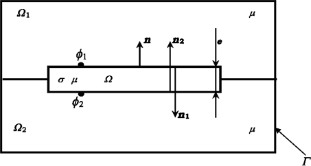
Consider an infinite plate of thickness e with two tangential fields H1s and H2s acting on its upper and lower surfaces (Figure 1.8). The analytic solution to Maxwell’s one-dimensional equations is given by the following relation:
Figure 1.8. Shell elements problem notation
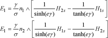
The electric field E at the plate’s surface is given by:
The electric field on the plate’s surfaces 1 and 2 is then:
These relations give a generalized surface impedance of the form:
[1.76] 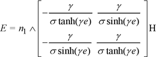
The solution on the boundary surfaces is given by:
In this case, the equation to solve is then:
[1.78] ![]()
with the boundary conditions at the plate surface expressed by the surface impedances of equation [1.76]. Equation [1.78] will be solved numerically.
To use the generalized shell elements in reduced scalar potential the conditions are [GUE 94]:
– region thickness very small compared to its other dimensions;
– region permeability near to that of the neighboring regions;
– no presence of multiply connected regions;
– if the skin effect is large, the source field must rather be tangential to the thin region’s surface.
The generalized shell element formulation developed in [GUE 94] uses the hypothesis that the thin region’s physical properties are isotropic. For anisotropic materials, we must extend this formulation to the cases of thin anisotropic regions with a tensorial electric conductivity [BEN 06].
1.5.2.3. Moment method
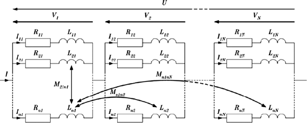
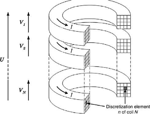
The principle of the MM consists of fractioning a set of N conductors (and/or a charge) into multiple n distinct inductor elements, within each of which current density is assumed to be constant. The discretization can be regular or not, depending on the conductor type, its dimensions, or the predictable current distribution inside it [CHE 95]. Generally speaking, for coils made of conductors with arbitrary cross-sections, this method can be presented by the Figure 1.9.
The whole elementary coil obtained in this way forms a mutually coupled device, which can be modeled using an equivalent electrical scheme.
1.5.2.3.1. Interactions between circuit elements
So far and in the absence of magnetic circuits, the equivalent electrical scheme of Figure 1.9 is equivalent to an associative parallel/series network of resistances and self- and mutual inductances (non-exhaustive representation of the mutual).
The resulting device is then governed by n.N first-order differential equations obtained from the modeled RL circuit, expressed with respect to either the currents Ii or the elementary magnetic induction flux ![]() ki. If all the quantities in play are sinusoidal, the various temporal differential operators can then be simplified by a factor involving the complex operator j and the pulsation
ki. If all the quantities in play are sinusoidal, the various temporal differential operators can then be simplified by a factor involving the complex operator j and the pulsation ![]() = 2
= 2![]()
![]() .
.
[1.79] 
Figure 1.9. MM principle: fractioning of inductor elements
It is also conceivable to apply the MM’s principle of mutuality to a similar network, taking the different parasite capacities between the elements into account [GUO 01].
Finally, knowing the modeling frequencies, solving the problem using this method simply consists of expressing the various inductances numerically [TAB 95] or analytically. By omitting the preceding indices from the formulation, we can define the law of conservation of magnetic flux going through a surface S, bounded by a closed loop C, by Stokes’ theorem. We can then calculate ![]() as a function of the magnetic vector potential A.
as a function of the magnetic vector potential A.
[1.80] ![]()
Generally speaking, the magnetic vector potential in an arbitrary point m, generated by a filiform inductor of length l with current I, is expressed by the following relation:
[1.81] 
The vector potential is thus collinear to the inductor, and ||r|| represents the distance between a point on the inductor and point m. For a current assumed to be unitary, formulas [1.79] and [1.80] yield a direct analytic solution to the self- and mutual inductances in a vacuum or in air.
1.5.2.3.2. Axisymmetrical case
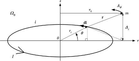
Let us consider a filiform coil, in air or vacuum, ![]() 0 (Figure 1.11) with current I, and with an associated cylindrical coordinate device (r,
0 (Figure 1.11) with current I, and with an associated cylindrical coordinate device (r,![]() , z). If we ignore helicity, the potential vector generated at point m has only one non-zero azimuthal component A
, z). If we ignore helicity, the potential vector generated at point m has only one non-zero azimuthal component A![]() , the expression for which can be deduced from the previous equation [DUR 68].
, the expression for which can be deduced from the previous equation [DUR 68].
[1.82] 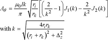
where J1 and J2 are the Legendre integrals of the first and second types. The Legendre integrals are defined for 0 ≤ k < 1, and can be approximated by limited developments (both classical and optimized). Generally speaking, for a conductor of any given cross-section, the current I can be expressed as a function of current density J, which means that the integral can be calculated numerically without worrying about the singularity at k = 1. For the analytic developments which will follow, we assume that this current density is uniform throughout the circular conductor cross-section S, and could also be used for conductors with rectangular cross-sections [BOU 89].
Figure 1.11. Vector potential created by a circular filiform coil
Let us consider the case shown in Figure 1.12, which consists of two conductive coaxial circular coils with circular cross-sections in a vacuum (or air).
Figure 1.12. Calculating the inductance of coaxial circular coils
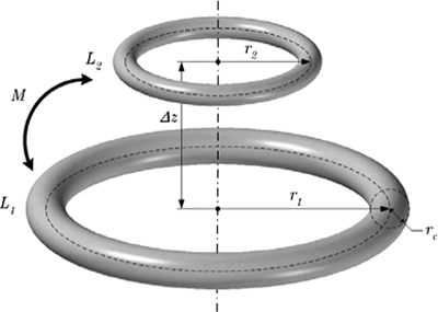
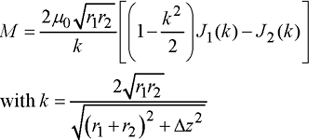
Mutual inductance M can be written from [1.79], [1.80] and [1.82]:
Self-inductance L1 (and similarly L2) is the sum of two terms. The first “internal” term Li is associated with the flux going through the section of the conductor between circles of radius r1 and r1–rc, and the second “external” term Le is due to the flux linkage of the coil of radius r1–rc. Assuming that the conductor’s radius is small compared to the coil’s radius, the inductance Li then becomes that of a cylinder of infinite length, i.e. ![]() 0/4
0/4![]() . Le is expressed from Stokes’ theorem for the contour of radius r1–r0, which can be approximated (using the polynomial expansions of J1 and J2) to:
. Le is expressed from Stokes’ theorem for the contour of radius r1–r0, which can be approximated (using the polynomial expansions of J1 and J2) to:
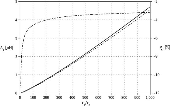
The expression mentioned above, which is valid for conductors with circular cross-sections, can also be considered for conductors with rectangular cross-sections. A comparison based on the previous analytical expression and a numerical calculation from [1.79], [1.81] and [1.82] shows that, for a large enough average coil radius, this approximation remains fairly accurate (Figure 1.13).
Figure 1.13. Proper inductances: conductors with equivalent square (—) and circular (---) cross-sections; relative error (—)
1.5.3. Numerical models
When the geometry of the electromagnetic and thermal devices is complex (or the physical properties depend on the field or temperature), the formulations derived in sections 1.2 and 1.3 cannot be solved analytically: numerical solutions are therefore required.
The basic principle of these methods is to discretize the studied problem to obtain a similar discrete problem, characterized by a finite number of unknowns.
The most commonly used methods for solving electromagnetic and thermal equations are the finite difference method [AME 77], the finite volume method [PAT 70], and the finite element method [DHA 05, BAS 03, DWO 88]. The finite difference method is used for axisymmetric or parallelelpiped-like geometries. The finite volumes method is used to solve hyperbolic, elliptic, or parabolic equations containing a divergence term. Finally, the finite element method is suited for each kind of system. In this book, we shall use the finite volume method to solve the thermal equation with regular geometry and the finite element method to solve the thermal equation and the electromagnetic equations with arbitrary geometry.
1.5.3.1. Finite volume method without velocity terms
In this method, the equation with partial derivatives is solved approximately using a grid of small disjoint volumes called finite volumes. The domain of study is the set of these small volumes.
Solving the heat equation using the finite volume method is based on the energy balance in an elementary volume. This balance can be written as follows:
[1.86] ![]()
where ![]() represents the thermal flux through the element’s surfaces, p the density per unit volume of the powers produced by the source in the element, v the volume element,
represents the thermal flux through the element’s surfaces, p the density per unit volume of the powers produced by the source in the element, v the volume element, ![]() the mass per unit volume, Cp the specific heat, and T the temperature. The flux
the mass per unit volume, Cp the specific heat, and T the temperature. The flux ![]() through each surface is calculated using the following Fourier relation:
through each surface is calculated using the following Fourier relation:
[1.87] ![]()
where ![]() is the thermal conductibility, s the surface, and n the outgoing vector normal to the surface.
is the thermal conductibility, s the surface, and n the outgoing vector normal to the surface.
For parallelepiped-like elements (Figure 1.14), the relations [1.86] and [1.87] become:
[1.88] 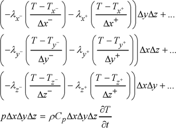
where T is the temperature at the center of the studied element and ![]() x,
x, ![]() y, and
y, and ![]() z are the element’s sides in the x, y, and z directions, respectively. The magnitudes with a negative sign represent the values in the negative direction of the appropriate axis, and those with a positive sign represent values in the positive direction. Thus, Tx- is the temperature at the center of the element to the left,
z are the element’s sides in the x, y, and z directions, respectively. The magnitudes with a negative sign represent the values in the negative direction of the appropriate axis, and those with a positive sign represent values in the positive direction. Thus, Tx- is the temperature at the center of the element to the left, ![]() x- is its thermal conductibility, and
x- is its thermal conductibility, and ![]() x- is the distance between the element centers to the left and the studied element.
x- is the distance between the element centers to the left and the studied element.
Figure 1.14. Parallelepiped-like element
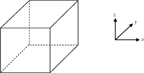
Writing this equation for all the elements of the mesh (taking boundary conditions into account) results in the following system of differential equations:
where, A is a sparse matrix, T is the temperature vector, P is the source power density vector, and I the identity matrix of order n, which is the number of elements. This system of equations is often solved using time steps ![]() t.
t.
[1.90] ![]()
where, k is the number of the current time step.
For nonlinear systems in which the thermal properties depend on temperature, equation [1.90] is solved iteratively.
For large temperature variations from one element to the next, the thermal conductivities of equation [1.88] must be replaced by their equivalent values at the interface. Let us consider the interface e between two elements P and E (Figure 1.15):
Figure 1.15. Interface between two elements
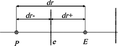
A one-dimensional analysis without source terms leads to the expression:
1.5.3.2. Finite volume method with a velocity term
If the material to be heated is in motion, the fluxes in equation [1.88] also contain the terms concerning mass transfer. For an interface e of surface area s, this term is calculated by the following expression:
where, Te is the temperature at the interface e, n the outgoing vector normal to the interface, and V the speed of the material there. If the material’s speed is low, Te is calculated using a linear interpolation between the temperatures of two elements on either sides of the interface. If the speed is large, however, a linear interpolation results in large errors in the calculation of temperature [PAT 70].
To overcome this complication, we use an analytical solution corresponding to the one-dimensional problem in each network. Let us consider equation [1.51] in one dimension in the u-direction without source terms:
with boundary conditions:
where Tj is the temperature at the center of element j, Tj+1 the temperature at the center of element j+1, and L the distance between the centers of both elements.
The solution of this equation is given by:
[1.95] 
with  the Péclet number (assumed to be constant) in the volume of the element. The temperature on the interface is then calculated by replacing u in [1.95] with the coordinates of the interface.
There are other methods for calculating Te, which can be more or less sophisticated than relation [1.95]. The presentation of these methods is beyond the context of this book. An interested reader can find information on these methods in [PAT 70].
1.5.3.3. Finite element method
The finite element method is the most commonly used numerical method to solve equations with partial derivatives. Using the variational formulation, it creates a spatial discretization to find an approximate solution to these equations. If the properties of the equations’ structure are conserved at the discrete level, the discrete solution approaches the exact solution more. Whitney elements have been and still are of great interest to finite element [BOS 98, REN 97, ALB 88, WEB 93].
Spatial discretization consists of cutting the domain of study ![]() in a finite number of simple elements (tetrahedrons, prisms…). Each element consists of
in a finite number of simple elements (tetrahedrons, prisms…). Each element consists of ![]() nodes,
nodes, ![]() edges, and
edges, and ![]() facets. The domain’s mesh then consists of the set of these entities. We will denote the number of nodes, edges, facets, and elements (tetrahedrical in this study) of the network by N, E, F, and V, respectively [DHA 05, DUL 96, LEM 99, BOS 93, HEN 04].
facets. The domain’s mesh then consists of the set of these entities. We will denote the number of nodes, edges, facets, and elements (tetrahedrical in this study) of the network by N, E, F, and V, respectively [DHA 05, DUL 96, LEM 99, BOS 93, HEN 04].
1.5.3.3.1. Nodal form functions
These are the 0th-order Whitney elements. To each mesh node n, we associate a scalar function wn, continuous over the entire domain of study, piecewise linear, equal to 1 at the node n and 0 at the other nodes of the mesh. With the nodal form functions, we can verify the following relation at each point in the domain:
The space generated by these functions is denoted by W0. Consequently, if ![]() is a scalar function defined in W0, then
is a scalar function defined in W0, then ![]() can be written as a linear combination of the functions wn:
can be written as a linear combination of the functions wn:
where, ![]() n represents the value of function
n represents the value of function ![]() at node n.
at node n.
1.5.3.3.2. Edge form functions
These are first-order Whitney elements. At each edge e with vertex ni and nj, we associate a vector function we such that:
wni and wnj are the nodal form functions associated with knots ni and nj. With the edge form functions, the circulation of we along edge e is equal to 1 and 0 at all other edges. The space generated by these form functions is noted W1. For a given vector v:
ve represents the circulation of v along edge e defined by:
The function we is continuous on each element and its tangential component is continuous when passing between two network elements.
1.5.3.3.3. Facet form functions
These are the second-order Whitney elements. For each facet ![]() (with vertices ni, nj, and nk) of the mesh, we associate a vectorial function wf:
(with vertices ni, nj, and nk) of the mesh, we associate a vectorial function wf:
wni, wnj, wnk are the nodal form functions associated with the nodes ni, nj, and nk.
The flux of wf going through facet ![]() is 1 and 0 for all other facets. The space generated by these functions is denoted by W2. If u is a function of W2, then:
is 1 and 0 for all other facets. The space generated by these functions is denoted by W2. If u is a function of W2, then:
where uf represents the flux of vector u through side ![]() , or:
, or:
The function wf is continuous in each mesh element and its normal component is conserved through all mesh facets.
1.5.3.3.4. Volume form functions
They are the third-order Whitney elements. To each volume v of the network, we associate a volume function wv such that:
where vol(v) is the volume of element v. The space generated by these functions is denoted by W3. If ![]() is a function of W3, then:
is a function of W3, then:
In this expression, ![]() v represents the volume integral of function
v represents the volume integral of function ![]() over element v.
over element v.
Referring back to the differential forms, the elements naturally suited to the discretization of the different scalar and vector variables in electromagnetism and heat transfer are:
– the nodal elements: electric and magnetic scalar potentials and temperature T;
– the edge elements: electric and magnetic vector potentials (T and A), electric and magnetic fields (E and H);
– facet elements: current density, magnetic, electric, and heat flux densities (J, B, D, and ![]() );
);
– volume elements: charge density ![]() v and power density p.
v and power density p.
1.5.3.3.5. Integral formulation
Let us consider a problem with partial derivatives of the form:
[1.106] ![]()
[1.107] ![]()
where, L is an nth order differential operator, B is an operator that defines the boundary conditions, ![]() and g are functions defined over
and g are functions defined over ![]() and
and ![]() , respectively. u is an unknown function over
, respectively. u is an unknown function over ![]() ∪
∪![]() . The problem with partial derivatives written in this form is called a strong formulation.
. The problem with partial derivatives written in this form is called a strong formulation.
We use a weak formulation of the problem by applying the method of weighted residuals [DHA 05]. This formulation leads to the following integral:
[1.108] ![]()
If u is a solution of [1.108] that verifies the boundary conditions defined by [1.107] for all test functions w, then u is also a solution of [1.106]. The great advantage of weak forms is that they are well suited for a numerical treatment and to the discretization by finite elements. To solve weak formulations in Wi spaces, we shall take the test functions w equal to the form functions, which is known as the Galerkin method. These functions can be wn, we, wf, or wv depending on the type of unknown under consideration.
If the unknown u belongs to a space with finite dimension Wi (i = 0, 1, 2, 3), then its interpolation in the Whitney elements space is:
The application of this relation for each function wi associated with each discrete entity (node, edge, facet, and volume) leads to a system of equations of the form:
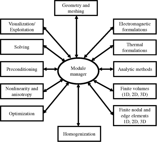
Since the three-dimensional problems are complicated by the size of the resulting matrices, preconditioning algorithms (along with iterative methods) become necessary to solve the resulting algebraic system. Further complications include the treatment of nonlinearity and anisotropy of some materials, such as composite materials. A computation and analysis software for coupled electromagnetic and thermal problems should therefore give all these necessary tools to answer these questions.
Figure 1.16. Computational software schema
