
3
Cooling the Data Center
3.1. System cooling technologies used
Cooling a “hot” device requires a “cold” fluid to capture its heat and transport it to the data center infrastructure, which will carry it away. In Chapter 2, we discussed how to extract the heat from an air-cooled device. In this Chapter 3, we discuss how the heat is transported and carried away by the data center cooling infrastructure and alternative cooling technologies.
Practically all the electrical power required in a data center is converted into heat, which has to be removed by a proper cooling system. The most suitable cooling solution should be designed, depending on the design criteria, to obtain a high energy efficiency, low cost and reliability. A cooling system should be designed to cover the worst-case scenario, although most servers generally work at much lower capacity than 100%. The control and prediction of temperature rising during a utility power outage is an important aspect for cooling system design. Air-cooled systems represent the backbone of data center cooling systems; they are evolving over the years to cope with the advance in the IT equipment. The evolution of air-cooled system is going toward localized cooling units and physical separation of the airstream within the data center in order to support the rising power densities. On the other hand, liquid-cooled systems are becoming promising and emergent solutions for cooling high power density data centers. Today, the IT equipment is reaching power densities that in some cases justify the liquid-cooled solutions; moreover, if the IT industry grows with the same trend of the recent years, air-cooled systems will not be able to accomplish the cooling process. The bulk cooling capacity is provided by the mechanical equipment: different systems such as chilled water systems, direct expansion air cooled systems and direct expansion glycol cooled systems are used. The heat rejection represents the last step in the heat removal process: cooling towers and dry coolers are the most common heat rejection systems for the data center industry.
3.2. Air-cooled data center
3.2.1. Conventional air-cooled data center
3.2.1.1. Machine room
Figure 3.1 represents a conventional air-cooled machine room.

Figure 3.1. Classic air-cooled machine room. For a color version of this figure, see www.iste.co.uk/brochard/energy.zip
At the periphery of the machine room are the CRAHs (Computer Room Air Handler), which extracts the hot air from the machine room and delivers cold air, as shown in Figure 3.2. In the center of the machine room, we find the IT equipment that are represented here by server racks, storage racks and tape robotics. CRAHs use fans, cooling coils and a water-chiller system to remove heat. This operation can cause some turbulence and hot spots in the machine room depending on the air flow and the heat capacity generated by the racks. The colors represent the temperature and red areas are hot spots (100°F/37.8°C) and dark blue areas are cold spot (60°F/15.5°C). These temperatures have to match the temperature supported by the IT equipment. For example, servers usually can operate at 35°C and under some conditions up to 45°C, while IT manufactures recommend a temperature between 18°C and 27°C.

Figure 3.2. Hot and cold air flows in the machine room. For a color version of this figure, see www.iste.co.uk/brochard/energy.zip
3.2.1.2. Refrigeration equipment
CRAHs by themselves do not produce cold air. The refrigeration equipment is usually outside the machine room, some on the data center roof, some in the basement or in an adjacent room. Table 3.1 presents a list of the cooling equipment.
Table 3.1. List and function of cooling equipment
| Name | Function | Energy needed |
| Chiller | produce cold water by a compressor mecanical action for CRAH or CDU | high |
| Cooling Tower | extract heat to the atmosphere from the hot water coming from data center by evaporative fluid material, cool it to near wet bulb temperature and return the cold water to the data center CRAH or water-side economizer | low |
| Dry-cooler | alternative to cooling tower using a closed circuit with air when outside temperature is too low for Cooling Tower, cool the "hot water" to near dry bulb temperature and return the "cold" water to the data center | medium low |
| Water-side economizer | extract heat from the hot air by a water condenser and reject it to the atmosphere via a dry cooler or cooling tower when enviromental conditions allow it | low |
| CRAH (Computer Room Air Handler) | extract hot air from the machine room with fans and blow cold air produced by the Chiller of Cooling Towers or Dry Coolers | low |
| CDU (Cooling Distribution Unit) | used in conjunction with RDHX to isolate and control the primary water loop from the secondary water loop | low |
| RDHX (Rear Door Heat eXchanger) | extract heat from the rack through a water circuit /coil with cold water produced from Chillers , Cooling Tower or Dry Cooler | low |
| In-Row Cooler | located in between racks to extract hot air from the machine room and return cold air produced by mecanical action | medium high |
3.2.1.3. Hot and cold aisle containment
The machine we have described so far with only CRAH in the machine room and chillers/cooling towers on the roof would have, under normal operation, a very bad efficiency, which is characterized by a PUE much larger than 1 and usually around 2. This is mainly due to the poor management of hot air and cold air with fans ingesting/blowing at the periphery of the machine room while the IT equipment is distant in the middle of the machine room. Different techniques are available to minimize the mixing of air flows. A very common and cheap one is the hot or cold aisle containment. It consists of organizing the racks in pairs of rows to isolate hot aisles and cold aisles from each other, and preventing hot and cold air from mixing by having the racks either back to back to blow their hot air in the hot aisle, or front to front to inlet the cold air in the cold aisle and by closing the aisle at each end and at the top to prevent the hot and cold air mixing within the machine room. In Figure 3.1, we see an example of cold aisle containment between the two rows of the servers’ racks with a blue-colored area in between the pair of rows.
3.3. ASHRAE data center cooling standards
The American Society of Heating, Refrigerating and Air Conditioning Engineers (ASHRAE) publishes 4,000+ standards for the design and maintenance of indoor environments. We are reproducing here some ASHRAE standards published by the Technical Committee 9.9 on Mission Critical Facilities, Data Centers, Technology Spaces and Electronic Equipment.
3.3.1. Operation and temperature classes
Temperature and operation of the data center is classified by ASHRAE.
Figure 3.3 presents four classes of ASHRAE TC 9.9 for Mission Critical Facilities, Technology Spaces & Electronics Equipment.
Classes are A1 with operating dry bulb room temperatures from 15°C to 32°C, A2 from 10°C to 35°C, A3 from 5°C to 40°C and A4 from 5°C to 45°C. Temperatures represent inlet temperature and humidity limits with altitude de-rating.

Figure 3.3. ASHRAE classes of data center operation. For a color version of this figure, see www.iste.co.uk/brochard/energy.zip
3.3.2. Liquid cooling classes
Table 3.2 presents the ASHRAE classification of liquid cooling classes from the Guide Line for Datacom Equipment Centers, Second Edition. The cooling classes are ranked from lower water temperature (W1) to higher water temperature (W5) and the cooling equipment required for each class. As we will see later, higher water temperature increases free cooling (see section 3.6) and improves TCO (see section 7.3).
Table 3.2. ASHRAE liquid cooling classes
| Liquid Cooling Classes | Main Cooling Equipment | Supplemental Cooling Equipment | Facility Water Temperature |
| W1 | Chiller/Cooling Tower | Water-side Economizer w/drycooler or cooling tower | 2°C–17°C |
| W2 | Chiller/Cooling Tower | Water-side Economizer w/drycooler or cooling tower | 2°C–27°C |
| W3 | Cooling Tower | Chiller | 2°C–32°C |
| W4 | Water-side Economizer w/drycooler or cooling tower | N/A | 2°C–45°C |
| W5 | Building Heating System | Cooling Tower | >45°C |
3.3.3. Server and rack power trend
Figure 3.4 presents the heat load trend from 2010 to 2020 per chassis and per racks published by ASHRAE.

Figure 3.4. ASHRAE 2015–2020 server power and rack heat load trends
It shows that servers are getting more power hungry and heat load per rack is moving from the 10–20 kW per rack to 40–50 kW per rack with dense power-hungry servers. We will present real examples of this trend in Chapters 4 when we discuss the processor and accelerator power and performance history, and in Chapter 5 when we present power and performance measurement of workload.
Figure 3.5 presents another way, the evolution of the rack heat load and their coling limits over time.

Figure 3.5. Data center rack cooling limits
The left Y-axis presents the air flow needed (in CFM) to cool the rack, with the corresponding heat load on the right side of the Y-axis. Full lines (red for 2U servers, orange for 1U servers and green for dense servers) represent the heat load of a 42-in nch rack full of such servers while the dotted lines represent the air-cooling limit for each type of servers. It shows that air-cooled racks will not be able to cool dense servers with heavy power load.
3.4. Liquid-cooled racks
As extracting heat from the periphery of the machine room is not efficient, a more effective solution is to extract heat from the back of the rack where fans are blowing hot air. A simple approach is to replace the rack door with a Rear Door Heat eXchanger (RDHX), as shown in Figure 3.6 and listed in Table 3.1.

Figure 3.6. Principle of passive RDHX. For a color version of this figure, see www.iste.co.uk/brochard/energy.zip
Passive RDHX replaces the existing rear doors of the IT enclosures. Chilled water circulates through the tube and fin coils above the dew point (no condensate). The RDHX has chilled water supply and return quick connections. Equipment exhaust air passes through the coil and is cooled before re-entering the room. Heat is removed from the room through the return water connection.
Figure 3.7 shows how RDHXs are connected to CDUs and Chillers through a primary and secondary loop.

Figure 3.7. RDHX, CDU and chillers. For a color version of this figure, see www.iste.co.uk/brochard/energy.zip
RDHX extraction capacity is limited since the RDHXs are passive, meaning there is no fan or mechanical action to help the heat extraction through the door. Figure 3.8 presents the passive RDHX capacity depending on the water temperature (in °C), the water flow rate (in gpm, gallon per minute) and the heat load of the rack (in kW). Please note the fan speed is the node fan speed in the server since RDHXs have no fan.

Figure 3.8. RDHX heat removal capacity for a 32 kW and 10 kW rack load. For a color version of this figure, see www.iste.co.uk/brochard/energy.zip
As we can see, depending on the rack heat capacity, inlet water temperature and water flow rate, a RDHX can absorb 100% of the heat or more meaning the RDHX is cooling the machine room. For the 32 kW heat load, 100% heat removal can be achieved with 10 gpm at 14°C or 12 gpm at 16°C, and 90% heat-to-water removal can be achieved with 8.5 gpm at 16°C or 11 gpm at 18°C. But a colder inlet water means more chiller work and a higher flow rate means more pump work and therefore more energy. That is the trade-off to be made to optimize the data center cooling and TCO, which is addressed in Chapter 7. When the rack load is very high (for example 40+ kW per rack, which occurs with dense servers using high TDP processors as shown in Chapter 4 and Figure 3.4), passive RDHX will not be able to extract 100% of the heat and either the remaining heat goes into the machine room air or other cooling devices have to be used, which is another trade-off to be made.
Active RDHX (ARDHX), which are offered by many companies, have fans inside the rear door to increase the airflow and the heat-to-water capacity at the expense of a higher cost and more power consumption.
Another similar technique is the “Hot Hut”, created by Google (Kava 2012). A “Hot Hut” consists first of a hot aisle containment with fans on top, which pull hot air across water-filed cooling coils and release the cooled air to the data center where servers/IT devices can use it again.
The impact of RDHX versus classic air-cooled center will be addressed on PUE and TCO in Chapter 5.
3.5. Liquid-cooled servers
RDHX is a more efficient way to cool a machine room for two major reasons. One is that heat is extracted closer to its source avoiding air turbulence and air mixing. Second is that water has a much higher heat capacity and much lower thermal resistance than air.
3.5.1. Water heat capacity
Figure 3.9 presents a comparison of the heat capacity and thermal resistance of water versus air.
cv is the heat capacity and:
is the 1D representation of the heat flux equation from thermodynamics, where q" is the heat flux, Rth is the thermal resistance and dT is the temperature gradient.
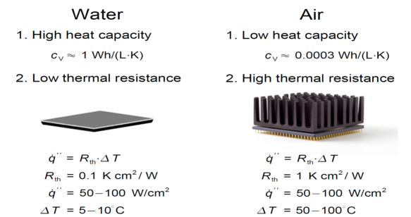
Figure 3.9. Water versus air heat capacity and thermal resistance. For a color version of this figure, see www.iste.co.uk/brochard/energy.zip
The consequence is that water requires a much smaller ∆T between the processor temperature and the inlet temperature than air. Therefore, to maintain a processor at temperature between 80 and 90°C, the inlet air temperature with air cooling has to be in the 20–30°C range, while the inlet water temperature can be up to 70°C. In practice, the highest inlet water temperature is in the 50–55°C range. Cooling directly the processor (or other active part of a node) with water is called direct water cooling (DWC) versus indirect water cooling as used with RDHX. Depending on the inlet water temperature, we will have cold (around 20°C), warm (around 30°C) or hot direct (40°C or higher) water cooling. We will come back to the influence of inlet water temperatures in Chapter 5.
3.5.2. Thermal conduction module
First utilizations of direct water-cooled technology were done with IBM thermal conductor module (TCM) for the IBM mainframes 3080 and 3090 in the 1980s–1990s (Blodgett and Barbour 1982). This expensive technology was needed due to the high-power consumption of these high-end processor (about 300 W per module). These processor and water-cooling technologies were slowly abandoned with the introduction of CMOS technology, which led to powerful microprocessors with a few watts of power consumption like CMOS VAX (Archer et al. 1987) and Intel 80x86 (Table 2.1). With the rise of CPU power consumption (205 W on Skylake, 250, 350 and 400 W on Cascade Lake) and GPU (300 W today and more in the future), water-cooling technology reappeared in the early 2010s for high-end commodity servers.
This is well illustrated in Figure 3.10.

Figure 3.10. Evolution of module heat flux from 1950 to 2020
More detail on the CPU and GPU power trend is discussed in section 4.1.
3.5.3. Full node heat removal with cold plates
The first large-scale commercial implementation of a water-cooled x86 server was done with the IBM iDataPlex dx360 m4, originally released as an air-cooled server in 2011 and delivered to LRZ SuperMUC in 2012 (IBM Newsroom 2012). Figure 3.11 presents the water loop assembly of the server.

Figure 3.11. Water loop assembly of the IBM iDataPlex dx360 m4. For a color version of this figure, see www.iste.co.uk/brochard/energy.zip
Besides the CPUs and memory modules, there are additional elements in a system board that require cooling, for example the voltage regulators (VRs) or the Intel platform controller hub (PCB). The water loop assembly covers all these elements and is composed of active and passive elements. For some of the onboard chips, such as the embedded service processor and other low power devices, passive water cooling is sufficient. Passive water cooling means the heat is extracted through a heat spreader connected to the water loop assembly before it goes to water. Active water cooling means the heat is extracted by cold plates, which are directly connected to the water loop. For the IBM iDataPlex dx360 m4, water flow rate is about 0.5 lpm (liters per minute) per node, inlet water temperature is between 20°C and 45°C and the heat-to-water ratio is up to 85% when the temperature delta between inlet water and room temperature is less than 15°C.
The water flow path is illustrated in Figure 3.12. Water enters the cooling loop through the left connector in the back of the chassis, flows to one CPU cold plate and to the second one in sequence and is then distributed in parallel over to the memory modules by the rear cold rail. After collecting heat from the memory modules by the front cold rail, water flows to the Patsburg Intel platform controller and exits the server through the right connector in the back.

Figure 3.12. Water flow path in the IBM iDataPlex dx360 m4. For a color version of this figure, see www.iste.co.uk/brochard/energy.zip
3.5.4. Modular heat removal with cold plates
As the cost to design and manufacture a full water-cooled server can be expensive, some companies are proposing kits of cold plate, tubing and manifolds to adapt on existing air-cooled servers by removing the heat sink and adding a water-cooled circuit. CoolIT1 and Asetek2 are offering such solutions for Intel and AMD CPUs, NVIDIA and AMD GPUs, and memory DIMMs. Some vendors are using such cooling devices to enable some of their servers with liquid cooling. The most common use of such modular solutions is to cool only the CPU or GPU of the server. We will study in Chapter 7 the PUE and TCO impacts of such a design, which we will call Hybrid, since only around 60% of the server heat goes to water while the remaining heat goes to air.
3.5.5. Immersion cooling
Immersion cooling is a different cooling technology based on liquid cooling where instead of using cold plates and heat spreader to cool the most power consuming parts, the server itself is totally immersed in a tank filled with some thermal conductive dielectric liquid coolant.
Immersion cooling has a higher heat-to-liquid ratio than cold-plate cooling as the whole heat of the server is extracted while cold-plate cooling heat-to-liquid ratio is between 60% and 90%. This allows more energy-efficient solutions and the ability to cool higher heat load racks. From a manufacturing perspective, it should be a simpler solution as no cold plate, and no tubing is added to the server. Still some modifications may be needed for immersion cooling. One modification is the need to take out the moving parts like fans. Another potential modification is the replacement of hydrocarbon-based thermal paste used between heat sinks and heat sources (see Figure 2.1) by thermally conductive epoxy-based material or Indium (Indium Corporation 2008) since thermal grease based on hydrocarbon will dissolve in the cooling liquid.
Immersion cooling can be used in two ways. With single-phase immersion cooling electronic components are immersed in a coolant in a sealed accessible tank where the coolant has a higher boiling point and remains in its liquid phase throughout the process. The heat from the chip is transferred to the coolant and classic pumps are used to flow the heated fluid to a heat exchanger and then cooled using the same techniques we presented previously such as cooling towers or dry coolers. With two-phase immersion electronic components are immerged in a sealed tank where the generated heat boils the coolant into a gaseous state, which rises to the top of the tank. The gas condenses on the lid or a condensation coil and drops back into the tank to repeat the cycle.
Immersion cooling has a great potential and dual-phase immersion can cool higher heat load servers or racks versus single phase. But it has also drawbacks like higher cost, potential safety issues and reliability problems of damaging electronics like power supply and logic boards (Coles and Herrlin 2016). That is why single-phase cooling has been used at some extent so far. It was used by Cray in a commercial product, Cray T90 (CEA 1996), and with commodity x86 servers in production (CGG 2012). But it has also some potential issues like reliability and maintainability, which has impacted its larger adoption. Nevertheless, immersion cooling is explored and tested today by IT companies (Alibaba Group 2018).
3.5.6. Recent DWC servers
There have been many other commercial DWC servers since 2012. We will focus on two of them: the IBM Power9 with NVIDIA V100, which was delivered as Summit to Oak Ridge National Lab, USA, and as Sierra to Lawrence Livermore National Lab, USA. These ranked, respectively, numbers 1 and 2 on Top500 in November 2018, and the Lenovo SD650 with Intel Xeon Skylake processor that was delivered as SuperMUC-NG to LRZ, Germany was ranked number 8. We will pay special attention to the SD650 since it is used to measure the power, thermal and performance impact of water cooling presented in Chapter 4 and in the TCO analysis presented in Chapter 5. It should be noted that in this Top10 of November 2018, four systems are water cooled: Summit, Sierra, SuperMUC-NG and Sequoia based on an IBM Blue Gene/Q system (IBM Icons n.d.).
3.5.6.1. IBM Power 9
IBM has been a pioneer of liquid cooling, starting with mainframes like the thermal conduction module (Blodgett and Barbour 1982) and later with Blue Gene (IBM Icons n.d.). For the Summit and Sierra systems that required very powerful and energy-efficient nodes, IBM coupled six NVIDIA V100 chips with two POWER 9 CPUs through NVLink (OLCF n.d.). Each compute node is DWC with eight cold plates (one per Power9 CPUs and one per V100 GPU). Each compute node is about 2.8 kW and each rack about 59 kW. This shows 50 kW per rack is today a reality. Inlet water temperature for the compute rack is 70°F (21.1°C) and the remaining racks are using RDHX.
3.5.6.2. Lenovo SD650
The Lenovo ThinkSystem SD650 is the third generation of water-cooled system after the iDataPlex dx360 m4 and the NeXtScale m360 m5.
Figure 3.13 presents one SD650 1 U tray, which hosts two-socket nodes side by side leading to a ½U density per 2S node. The water circuit is cooling in parallel the two nodes on the tray to minimize the water-cooling costs. The water path enters the tray through the blue arrow inlet, is split into two water paths (one for each node) and split again into two water paths, one for the CPUs and one for the 12 DDR4 DIMMs and four Apache Pass (AEP) slots, which are not populated on Skylake but will be on Cascade Lake when Optane DC Persistent Memory (or Optane DIMMs) is supported. The CPU water flow is going first to the CPU slot 1 (highlighted in green), then to CPU slot 2 (highlighted in red) and finally going to the outlet (highlighted in yellow). The impact of such water flow on the processor temperature will be presented in Chapter 5.

Figure 3.13. Lenovo ThinkSystem SD650 water-cooled node. For a color version of this figure, see www.iste.co.uk/brochard/energy.zip
The memory water flow is shown in Figure 3.14. Water flows in six parallel different streams to cool the DDR4 DIMMs and AEP slots, and a conductive plate conducts the heat from the disk and network cards to the memory water path.
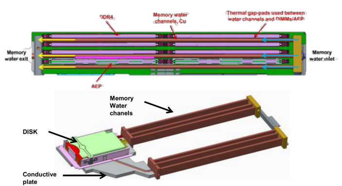
Figure 3.14. Lenovo ThinkSystem SD650 memory water channels. For a color version of this figure, see www.iste.co.uk/brochard/energy.zip
From a cooling perspective, the major differences between the SD650 and iDataPlex dx360 m4 are:
- – higher TDP processors are supported (205 W SKU and even 240 W SKU under some conditions vs. 150 W SKU);
- – higher heat-to-water ratio as all devices, except the power supply, are cooled with a better efficiency. For example, 95% of heat is going to water if the room temperature and inlet water temperature are within the following bounds: (air 5–35°C; water 10–50°C);
- – higher flow rate of 0.7 lpm per node versus 0.5 lpm per node;
- – wider range of inlet water temperature is supported (10–50°C vs. 18–45°C).
It should be noted that SD650 is a ½U 2S server with a shadow processor configuration (Figure 2.9) with water flowing first to CPU0 and then CPU1. This cooling difference impacts the CPU temperature and will be discussed in Chapter 5.
3.6. Free cooling
Free cooling occurs when chillers are not needed to produce cold water and cooling towers or dry coolers can be used instead. Hence, the name “free” cooling since the only power needed is for the pumps and fans when the free-cooling capacity can cover 100% of the need. Therefore, free-cooling usage depends on the environmental conditions, and in particular the outside temperature. Free cooling can start as soon as the temperature difference between the cold-water temperature going to the CRAH, the RDHX or the DWC loop and the outside temperature is between 2°F (1°C) and 4°F (2°C), which is pretty low. Therefore, increasing the room temperature and the water temperature will increase the free cooling of the system and reduces dramatically its PUE and TCO (see section 7.3).
3.7. Waste heat reuse
3.7.1. Reusing heat as heat
The simplest way to reuse waste heat is to use it for heating purposes. A few data centers have been doing it to heat their offices (see Chapter 7 for NREL and LRZ) or heating buildings close by or heating pools (Munroe 2016). The two major drawbacks of reusing waste heat for heating are the difficulty of transporting heat and the temperature of the exhausted heat needed. As the cost of insulated piping to carry and minimize heat loss is expensive, the cheapest way to circumvent the first difficulty is to choose a close “heating target”, which explains why this reuse of waste heat is still limited to the data center offices or close by buildings. Regarding the second difficulty related to the temperature of the exhausted heat, the temperature at which the data center operates is crucial. For an air-cooled data center using cold water to feed the CRAH, RDHX or DWC when return temperature is between 28°C (82°F) and 35°C (95°F), heat pumps can be used to increase the heat temperature to 55°C or more, which is the minimum temperature required to reuse efficiently heat, which means inlet water temperature is about 5°C lower. This means that if the inlet water temperature at which the data center operates has to be at least 23°C (73°F). This is well above the temperature at which conventional air-cooled data center operates, which is between 5°C (41°F) and 12°C (72°F). This means the data center needs to operate at higher temperature, like W2 or higher according to ASHRAE operating classes (Figure 3.4). Another potential drawback of such an approach is that the quantity of heat generated by the data center can be larger than the heating quantity needed by the “heating target” and that the need to heat a building is seasonal. In this case, storing the excess energy is a potential solution, which we will discuss in section 7.4. It should be noted that water cooling can minimize the difficulties we just described since a water-cooled system using warm water with inlet water temperatures like 30°C (86°F) will generate outlet water around 35°C (95°F), and possibly higher, up to 45–50°C, inlet water temperature with hot water cooling.
3.7.2. Transforming heat with adsorption chillers
Transforming heat into cold has been for a long time restricted to high temperature. Adsorption chillers are a new type of machine that is quite different from the previous generation of liquid desiccant absorption chillers. With solid desiccant adsorbers, the desiccant never moves and never changes phase. It is always a solid. There are very few moving parts and no chemicals. In fact, the refrigerant used is regular tap water with no additional additives. The unique property of adsorption machines is their ability to operate at reduced hot water temperatures as low as 130°F (54°C).
3.7.2.1. Adsorption chillers
Adsorption chillers generate chilled water using heat as the primary energy source. Contrary to the more common absorption chillers, the heatpumping effect is generated by a solid instead of a liquid sorption material, which absorbs the refrigerant, typically water. They are being applied, when only low-temperature waste heat is available.
Adsorption chillers are generally designed in two different ways:
- – Option 1 design: two-chamber approach using the same heat exchanger for evaporation and condensation of water vapor;
- – Option 2 design: four-chamber approach with separated heat exchangers for evaporation and condensation.
As shown in Figure 3.15, an adsorption chiller based on design option 1 consists of two identical vacuum containers, each containing two heat exchangers:
- – Adsorber: coated with the adsorbent (silica gel or zeolite);
- – Phase changer: evaporation and condensation of water.
- – During desorption (module 1), the adsorbent is heated up causing the previously adsorbed water vapor to flow to the condenser (red arrow), where it is condensed to liquid water.
- – During adsorption (module 2), the adsorbent is cooled down again causing water vapor to flow back (blue arrow) and evaporate in the evaporator generating cold. Water is evaporated at low temperatures, because the system is evacuated and hermetically sealed from the surroundings.
- – Two (or more) identical modules operate phase-shifted to provide continuous cooling.
In the option 2, design evaporation and condensation of the water vapor are carried out in separated vacuum chambers. This approach leads to a system as shown in Figure 3.16.

Figure 3.15. Adsorption chiller principle and phases (two chambers design). For a color version of this figure, see www.iste.co.uk/brochard/energy.zip
While in the option 1 design, the chiller consists of two or more adsorbers, which are alternatively heated and cooled in order to cause desorption and adsorption of water vapor, in the option 2 design (Figure 3.16), the right adsorber is being desorbed, whereas the left adsorber is adsorbing. In the next step, hot water and cooling water are switched and the right adsorber is in adsorption and the left adsorber in desorption state. Evaporation and condensation of the water vapor are carried out in separated vacuum containers where temperature is constant, which was not the case with option 1 design where temperature changed continuously. In order to close the refrigerant loop, the liquid condensate is returned to the evaporator.

Figure 3.16. Adsorption chiller principle and phases (four containers design). For a color version of this figure, see www.iste.co.uk/brochard/energy.zip
This design needs four vacuum valves, which also may operate passively by internal pressure differences, controlling the refrigerant flow and which sets higher requirements in designing a vacuum-tight system. On the other hand, due to the constant temperatures of evaporator and condenser, thermal coefficient of performance (COP) and cooling capacity are better. Moreover, because of lower internal temperature losses, higher temperature lifts may be achieved, which is especially important, if the waste heat temperature to the machine is low.
Such new generation adsorption chillers, with inlet hot water coming from the compute racks at about 55°C water temperature can produce cold water at around 20°C.
3.7.2.2. Coefficient of performance
In adsorption chillers, two types of energy are used to drive the machine: heat and electricity. Therefore, a distinction has to be made between thermal and electrical efficiency called the coefficient of performance (COP). In a data center, the adsorption chiller is cooling the hot fluid loop (HF) from the compute racks using this heat flow to generate chilled water to befed into the cold fluid loop (CF) using electricity (EL). Figure 3.17 summarizes this in the Sankey diagram.

Figure 3.17. Sankey diagram of the energy flows in an adsorption chiller. For a color version of this figure, see www.iste.co.uk/brochard/energy.zip
For the thermal efficiency, an adsorption chiller can be seen as a heating or cooling system. The thermal coefficient of performance of a heating or cooling system is measured by COPheating and COPheating as the ratio of heat removed or supplied to the energy required3.
For COPcooling, this means how much cold the chiller produces (Qcf) and how much waste heat is needed to produce this amount of cold (Qhf).
For COPheating, the medium temperature output of the chiller is compared to the high temperature heat input (Qhf). Because of energy conservation, this output is the sum of the two inputs (Qcf + Qhf), leading to:


which leads to:

and:

For the electrical efficiency, the electrical COP (COPel) is the ratio between the total amount of heat removed from the data center to the ambient (Qcf + Qhf), divided by the total amount of electricity Pel needed for this task. Adsorption chillers only need electricity for the controller and switching of hydraulic valves, therefore its share of the electricity demand is negligible. Thus, the electricity demand to be included into the calculation of COPel is dominated by the pumps and fans of the hydraulic installation.
Therefore, we have:

Comparing an adsorption chiller with a conventional electrical chiller, the overall electrical COP is of major interest.
The different cooling technologies we have described so far (conventional chillers and adsorption chillers) have very different COPel.
Figure 3.18 presents the COPel for adsorption chillers (adsorption cooling total), conventional chillers (compression cooling) and free cooling as measured on the CoolMUC-2 system at LRZ (see section 7.2). A higher COPel value means a more efficient cooling system leading to a lower PUE.
It shows that the energy efficiency of adsorption cooling is much higher than compression cooling and very close to free cooling since the electricity needed to power the adsorption chillers and its pumps is very low: for 1 kW of chilled water produced, adsorption cooling requires 65 W, while compression cooling requires 301 W and mixed compression plus free cooling requires 132 W.
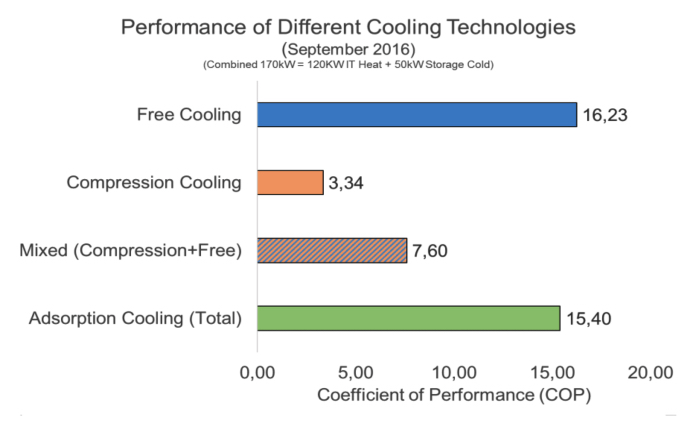
Figure 3.18. Measured COPel values of different cooling technologies. For a color version of this figure, see www.iste.co.uk/brochard/energy.zip
From now on, we will measure the thermal efficiency of adsorption chillers using COPcooling as defined in [3.2], which we will simply call COP.
3.7.2.3. Coefficient of performance and hot water
For quite some time, thermal driven cooling was dominated by liquid absorption chillers based on lithium/bromide-water or ammonia-water as sorption pairs, which do not operate at hot water temperatures between 45 and 55°C, which are typical for data centers using hot water cooling.
Adsorption chillers based on the solid adsorption material silica gel and water as refrigerant can generate chilled water at 18–20°C at a hot water temperature around 55°C with a COP of 50% as we will see in section 7.2.3. But with desorption temperatures of 55°C and less, the capacity of the silica gel chiller is considerably below its performance in the usual field of operation at driving temperatures between 70 and 90°C, which leads to the necessity of installing large units compared to the supplied cooling capacity.
In order to overcome this drawback, a series of R&D activities are currently being performed with the aim to develop a more compact adsorption chiller, which is specifically adapted to the conditions in data centers. These activities are mainly concentrated on choosing adsorption materials with adsorption characteristics, which are better adapted to the temperature conditions in data centers, as well as coating heat exchanger surfaces with these materials, in order to enhance heat and mass transfer in the adsorber.
The significance of the properties of the adsorption material and the heat and mass transfer between adsorbent and heat exchanger walls in the adsorber may be easily understood, if the basic terms influencing COP [3.2] and the specific cooling power (SCP) are taken into consideration:


where Hev and Had are the enthalpy of evaporation and adsorption, m is the mass of adsorption material in the adsorber, ∆X is the specific water uptake of the adsorbent during adsorption, Cev and Cad are the thermal mass of the evaporator and the adsorber, ∆Tev and ∆Tad are the temperature swing of evaporator and adsorber, tcyc is the cycle time and V is the volume of the machine.
The design target of adsorption chillers is to keep the thermal masses of adsorber and evaporator as small as possible and avoid a thermal swing in the evaporator as done with option 2 design. Due to the considerably lower thermal conductivity of adsorption materials, a reduction of thermal mass (and consequently the heat exchanger surface of the adsorber) improves COP but also increases the cycle time tcyc and leads to lower SCP [3.9]. Therefore, the dominant term which positively influences COP and SCP is m • ∆X.
Recently, a series of new adsorption materials have been studied as an alternative to silica gel in the field of lower driving temperatures. The most prominent groups of materials are a certain class of zeolites, where silicon is exchanged with phosphor (AlPOs) and metal organic frameworks (MOFs). These materials have the property that a large portion of the overall adsorption capacity is adsorbed in a very narrow range of temperature and vapor pressure conditions. Choosing a material, with its range within the limits of the operation conditions, leads to a considerably higher water uptake than for silica gel.

Figure 3.19. Water uptake of new adsorbent material. For a color version of this figure, see www.iste.co.uk/brochard/energy.zip
Figure 3.19 presents the water uptake of new adsorbents (zeolite AlPO-5 and MOF aluminum fumarate Al-Fu) versus silica gel at temperatures between 45°C and 55°C (outlet water temperature of the water-cooled servers) at an evaporation temperature of 18°C and an adsorption and condensation temperature of 30°C.
These new materials are very promising because for both groups of materials (zeolites and MOFs), coating technologies enable the adsorbents increase in mass in the adsorber while keeping good heat and mass transfer.
For zeolites, SorTech AG (now Fahrenheit GmbH) has developed a coating method that is based on direct crystallization of zeolite on heat exchanger surfaces by partial support transformation of the aluminum surface into zeolite, provided that the aluminum atoms to be incorporated into the lattice of zeolite during synthesis. This process leads to a very dense and stable layer of zeolite on the heat exchangers surface and ensures a good heat and mass transfer for high SCP (Wittstadt et al. 2017).
For MOFs, the Fraunhofer-Institute for Solar Energy Systems (ISE) has developed a binder-based coating method, as well a direct crystallization on heat-exchanger surfaces, thus solving the technical task of heat and mass transfer in a similar manner as with zeolite (Fröhlich et al. 2016)
Although there is no optimized adsorption chiller for data center applications on the market up to now (January 2019), these new approaches will boost the development of low-temperature chillers and novel products are expected in the near future.
- 1 Available at: https://www.coolitsystems.com/technology [Accessed April 30, 2019].
- 2 Available at: https://www.asetek.com/data-center/solutions-for-data-centers [Accessed April 29, 2019].
- 3 Available at: https://en.wikipedia.org/wiki/Coefficient_of_performance#Equation [Accessed May 1, 2019].