Here's my design; how well does it work?
DESIGN RESULTS can be communicated in several ways. In this chapter we focus on how to translate our design ideas into models and prototypes that can be used to test our design concepts and communicate our ideas to the client. Often the first step in such a process involves sketching or drawing our design, as we discussed in Chapter 9, because we can use these representations to create the prototype or model. One useful tool for this process is a three-dimensional (3D) representation of the designed object in a software program such as Cleo Elements/Pro™ (formerly ProEngineer) or SolidWorks™. This 3D representation can then be used: (1) as an input to a computational modeling program to simulate the design's performance under specified conditions; (2) as an input into a variety of rapid prototyping technologies, such as 3D printing; (3) to generate detailed engineering drawings of the design; and (4) to guide the tool path in computer numerical-controlled (CNC) machining. We now describe a few common modeling and prototyping tools.
10.1 PROTOTYPES, MODELS, AND PROOFS OF CONCEPT
For many engineering projects, we want to build three-dimensional, physical realizations of our concepts and designed artifacts. There are several versions of physical things that could be made—including prototypes, models, and proofs of concept—and they are often made by their designers.
Prototypes are “original models on which something is patterned.” They are also defined as the “first full-scale and usually functional forms of a new type or design of a construction (such as an airplane).” In this context, prototypes are working models of designed artifacts. They are tested in the same operating environments in which they're expected to function as final products. It is interesting that aircraft companies routinely build prototypes, while rarely, if ever, does anyone build a prototype of a building.
A model is “a miniature representation of something,” or a “pattern of something to be made,” or “an example for imitation or emulation.” We use models to represent some devices or processes. They may be paper models or computer models or physical models. We use them to illustrate certain behaviors or phenomena as we try to verify the validity of an underlying (predictive) theory. Models are usually smaller and made of different materials than are the original artifacts they represent, and they are typically tested in a laboratory or in some other controlled environment to validate their expected behavior.
A proof of concept, in this context, refers to a model of some part of a design that is used specifically to test whether a particular concept will actually work as proposed. Doing proof-of-concept tests means doing controlled experiments to prove or disprove a concept.
10.1.1 Prototypes and Models Are Not the Same Thing
The definitions of prototypes and models sound enough alike that it prompts a question: Are prototypes and models the same thing? The answer is, “Not exactly.” The distinctions between prototypes and models may have more to do with the intent behind their making and the environments in which they are tested than with any clear dictionary-type differences. Prototypes are intended to demonstrate that a product will function as designed, so they are tested in their actual operating environments or in similar, uncontrolled environments that are as close to their relevant “real worlds” as possible. Models are intentionally tested in controlled environments that allow the model builder (and the designer, if they are not the same person) to understand the particular behavior or phenomenon that is being modeled. An airplane prototype is made of the same materials and has the same size, shape, and configuration as those intended to fly in that series (i.e., Boeing 747s or Airbus 310s). A model airplane would likely be much smaller. It might be “flown” in a wind tunnel or for sheer enjoyment, but it is not a prototype. A prototype is the first of its kind; a model represents a device or a process.
Engineers often build models of buildings, for example, to do wind-tunnel testing of proposed skyscrapers, but these models are not prototypes. Rather, building models used in a wind-tunnel simulation of a cityscape with a new high-rise are essentially toy building blocks that are meant to imitate the skyline. They are not buildings that work in the sense of aircraft prototypes that actually fly. So, why do aeronautical engineers build prototype airplanes, while civil engineers do not build prototype buildings? What do they do in other fields?
10.1.2 Testing Prototypes and Models, and Proving Concepts
We introduced testing in discussing both models and prototypes. In design the type of testing that is often most important is proof of concept testing in which a new concept, or a particular device or configuration, can be shown to work in the manner in which it was designed. When Alexander Graham Bell successfully summoned his assistant from another room with his new-fangled gadget, Bell had proven the concept of the telephone. Similarly, when John Bardeen, Walter Houser Brattain, and William Bradford Shockley successfully controlled the flow of electrons through crystals, they proved the concept of the solid-state electronic valve, know as the transistor, that replaced vacuum tubes. Laboratory demonstrations of wing structures and building connections can also be considered as proof-of-concept tests when they are used to validate a new wing structure configuration or a new kind of connection. In fact, even market surveys of new products—where samples are mailed out or stuffed into sacks in the Sunday papers—can be conceived of as proof-of-concept tests that test the receptivity of a target market to a new product.
Proof-of-concept tests are scientific endeavors. We set out reasoned and supported hypotheses that are tested and then validated or disproved. Turning on a new artifact and seeing whether or not it “works” is not a proper proof-of-concept demonstration. An experiment must be designed, with hypotheses to be disproved if certain outcomes result. Remember that prototypes and models differ in their underlying “reasons for being” and in their testing environments. While models are tested in controlled or laboratory environments, and prototypes are tested in uncontrolled or “real-world” environments, both are controlled tests. Similarly, when we are doing proof-of-concept tests, we are doing controlled experiments in which the failure to disprove a concept may be key.
For example, suppose we had chosen Mylar containers as our new juice product and designed them to withstand shipping and handling, both in the manufacturing plant and in the store. If we think of all of the things that could go awry (e.g., stacks of shipping pallets that could topple) and analyze the mechanics of what happens in such incidents, then we might conclude that the principal design criterion is that the Mylar containers should withstand a force of X Newtons (N). We would then set up an experiment in which we apply a force of X N, perhaps by dropping the containers from a properly calculated height. If the bags survived that drop, we could say that they'd likely survive shipping and handling. However, we could not absolutely guarantee survival because there is no way we could completely anticipate every conceivable thing that might happen to a beverage-filled Mylar container. On the other hand, if the Mylar container fails a properly designed drop test, we can then be certain that it will not survive shipping and handling, and so our concept is disproved. The National Aeronautics and Space Administration (NASA) conducted a similar proof-of-concept test for gas-filled shock absorbers for one of the Mars landers. There are potential issues of legal liability involved in product testing (for example, for how much nonstandard use of a product can a manufacturer be held responsible?), but they are beyond the scope of this text.
Prototypes, models, and proof-of-concept testing have design because of their intents and test environments. These mind while planning them for the design process.
10.1.3 When Do We Build a Prototype?
The answer is, “It depends.” The decision to build a prototype depends on a number of things, including: the size and type of the design space, the costs of building a prototype, the ease of building that prototype, the role that a full-size prototype might play in ensuring the widespread acceptance of a new design, and the number of copies of the final artifact that are expected to be made or built. Aircraft and buildings provide interesting illustrations because of ample commonalities and sharp differences. The design spaces of both aircraft and high-rises are large and complex. There are millions of parts in each of these examples, and so many design choices are made along the way. The costs of building both airplanes and tall buildings are also quite high. In addition, at this point in time, we have ample experience with both aeronautical and structural technologies, so that we generally have a pretty good idea of what we're about in these two domains. So, again, why prototype aircraft and not prototype buildings? In fact, don't the complexity and expense of building even a prototype aircraft argue directly against the idea of building such prototypes?
Notwithstanding all of our past experience with successful aircraft, we build prototypes of airplanes because, in large part, the chances of a catastrophic failure of a “paper design” are still unacceptably high, especially for the highly regulated and very competitive commercial airline industry that is the customer for new civilian aircraft. That is, we are simply not willing to pay the price of having a brand new airplane take off for the first time with a full load of passengers, only to watch hundreds of lives being lost—as well as the concomitant loss of investment and of confidence in future variants of that particular plane. It is in part an ethical issue, because we do bear responsibilities for technical decisions when they impinge upon our fellow humans. It is also in part an economic issue, because the cost of a prototype is economically justifiable when weighed against potential losses. When we build prototypes of airplanes those particular planes are not simply thrown away as “losses” after testing; they are retained and used as the first in the series of the many full-size designs that are the rest of the fleet of that kind of airplane.
Buildings do fail catastrophically, during and after construction. However, this occurs so rarely that there is little perceived value in requiring prototype testing of buildings before occupancy. Building failures are rare in part because high-rises can be tested, inspected, and experienced gradually, as they are being built, floor by floor. The continuous inspection that takes place during the construction of a building, from the foundation on up, has its counterpart in the numerous inspections and certifications that accompany the manufacture and assembly of a commercial airliner. But the maiden flight of an airplane is a binary issue, that is, the plane either flies or it doesn't, and a failure is not likely to be a graceful degradation!
Another interesting aspect of comparing the design and testing of airplanes to that of buildings has to do with the number of copies being made. We have already noted that prototype aircraft are not discarded after their initial test flights; they are flown and used. In fact, airframe manufacturers are in business to build and sell as many copies of their prototype aircraft as they can, so engineering economics plays a role in the decision to build a prototype. The economics are complicated because the manufacturing cost of the first plane in a series is very high. Technical decisions are made about the kinds of tooling and the numbers of machines needed to make an airplane, and economic trade-offs between the anticipated revenue from the sale of the airplane and the cost the manufacturing process are evaluated. We will address some manufacturing cost issues in Chapter 13.
Another lesson we can learn from thinking about buildings and airplanes is that there is no obvious correlation between the size and cost of prototyping—or the decision to build a prototype—and the size and type of the design space. And while it might seem that the decision to build a prototype might be strongly influenced by the relative ease of building it, the aircraft case shows that there are times when even costly, complicated prototypes must be built. On the other hand, if it is cheap and easy to do, then it generally would seem a good idea to build a prototype. There certainly are instances where prototypes are commonplace, for example, in the software business. Long before a new program is shrink-wrapped and shipped, it is alpha- and beta-tested as early versions are prototyped, tested, evaluated, and, hopefully, fixed.
If there is a single lesson about prototypes, it is that the project schedule and budget should reflect plans for building them. More often than not a prototype is required, although there may be instances in which resources or time are not available. In weapons development contracts, for example, the U.S. Department of Defense virtually always requires that design concepts be demonstrated so that their performance can be evaluated before costly procurements. At the same time, it is interesting that aircraft companies (and others) are demonstrating that advances in computer-aided design and analysis allow them to replace some elements of prototype development with sophisticated simulation.
Sometimes we build prototypes of parts of large, complex systems to use as models to check how well those parts behave or function. For example, structural engineers build full-size connections, say, at a point where several columns and beams intersect in a geometrically complicated way, and test them in the laboratory. Similarly, aeronautical engineers build full-size airplane wings and load them with sandbags to validate analytical models of how these wing structures behave when loaded. A prototype of a part of a larger artifact is built in both instances, and then used to model behavior that needed to be understood as part of completing the overall design. We use prototypes to demonstrate functionality in the real world of the object being designed, and we use models in the laboratory to investigate and validate behavior of a miniature or of part of a large system.
10.2 BUILDING MODELS AND PROTOTYPES
There are principles behind and guidelines for building and testing prototypes and models. The important questions we must ask are: What do we want to learn from the model or prototype? Who is going to make it? What parts or components can be bought? How, and from what, is it going to be made? How much will it cost? We have already answered the first question in Section 10.1, but we should keep our answers in mind as we turn to the implementation details of (actually) building a model or a prototype.
10.2.1 Who Is Going to Make It?
We have two basic choices when we want a model or prototype: we make and/or assemble it in-house or we outsource it. With sufficient time and money, we can make just about anything we want, from an application-specific integrated circuit to a computational-fluid-dynamics (CFD) model of a pressure relief valve to a pilot-scale oil refinery. Three major factors enter into the decision about who makes our model: expertise, expense, and time.
Many companies and schools keep machinists, electronics technicians, and programmers on staff for building models. They often have facilities that individuals can use to build prototypes, and some schools even require students to learn how to use such facilities. However, it is rather rare to have facilities or expertise for making intricate or tight-tolerance items. Thus, we first want to ask if anyone on our design team has the necessary expertise, or is willing to learn. We should identify expertise and facilities that are available in-house. If the needed expertise is missing in-house, we should plan on having parts or components outsourced.
Time and cost are usually intertwined. If we need a part “yesterday,” it's not likely that we can outsource it without a spending a lot of money, but we may be able to go to our own machine shop and machine it in an hour. However, engineers aren't always allowed to use their company's machine shop, so we might have to convince a machinist to do it. Then the likelihood of getting it done right away will depend on the machinist's workload and her willingness to oblige. We can see that it is a good idea to cultivate good relationships with a company's (or a school's!) machinists and technicians. It is always a good idea to try to give them meaningful lead times, to ask their advice often, and to not ask for things that are silly or impossible. Treat technicians and machinists—and indeed, all staff—as professionals and as equals. In addition to being the right thing to do, this will make it much more likely that we can get their help when we need it.
Sometimes, especially for specialized items, it may still be cheaper and/or faster to have specific items outsourced. For example, gears and printed circuit boards are likely to be gotten cheaper and faster when outsourced.
If we do something outsourced, it will go much more smoothly if we prepare detailed specifications for what we are outsourcing. That might include properly drawn, toleranced, and specified mechanical drawings for machined or manufactured parts (see Chapter 9); accurate and double-checked Gerber files for printed circuit boards; or complete and correct part numbers for parts or components.
10.2.2 Can We Buy Parts or Components?
There are a lot of parts and components that are best bought from suppliers, unless we happen to be in the business of designing and making those particular items. For example, it is rarely worth the time, equipment, and expense to make screws or transistors: Common mass-produced items should always be bought—although it also a good idea to check your institution's stockroom(s) to see whether the parts are already available. Fasteners, such as nails, nuts, bolts, screws, and retaining rings should almost always be bought, as should common mechanical parts or devices such as pulleys, wheels, gears, casters, transmissions, and hinges. Similarly, electronic, electromechanical, and optical components such as resistors, capacitors, integrated circuits, electric motors, solenoids, light-emitting diodes (LEDs), lenses, and photodiodes can be bought.
TABLE 10.1 A short list of suppliers and their URLs for a variety of products that might be useful in building models and prototypes
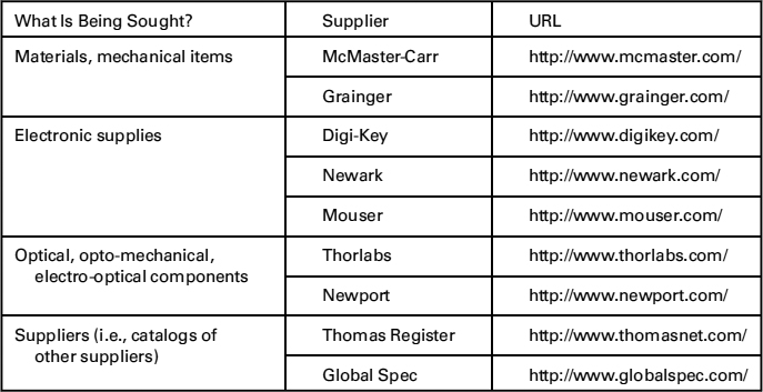
The Internet and the widespread use of just-in-time manufacturing have dramatically changed the ease with which we can find suppliers and parts. We show a list of some widely available suppliers and their URLs in Table 10.1. Many companies allow online ordering and provide fast (i.e., overnight) shipping of in-stock items. Some companies will ship both small lots and large quantities, and some websites provide excellent search capabilities (assuming we know the proper term for the part we want) and display real-time inventories.
It really does pay to spend some time searching for parts and components. An experienced engineer or a librarian can often be very helpful as we search. We should note the prices or cost when we find what we want because that will come in handy for our budget. We can likely find many, or even all, of our prototype components already available online or in a store—and it's far better to learn that before we start building, instead of just as we finish.
10.2.3 How, and from What, Will the Model/Prototype Be Made?
Now we turn to basic principles and best practices for making, machining, and assembling mechanical parts. The carpenter's maxim is: measure twice, cut once. We should create detailed, annotated drawings and plans before we start cutting or machining: it will pay huge dividends in ensuring that things fit together the very first time they are assembled, and will surely minimize reworking the problem or the parts.
Detailed plans should include a bill of materials, which we will describe in Chapter 13 as an important aspect of engineering economics in design. It is easier to construct a bill of materials during a virtual or paper assembly, and so identify all of the necessary parts before everything has been done. Then we can check on the availability of the parts to help our scheduling. It may also be useful to construct a process router: a list of instructions for how the prototype is to be fabricated and assembled.
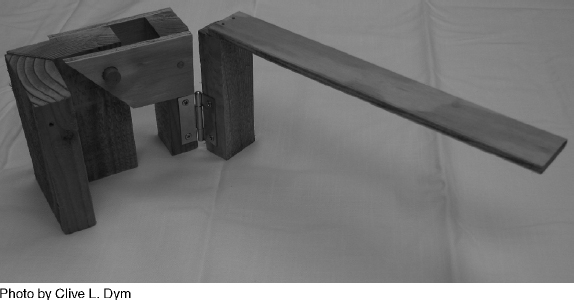
Figure 10.1 Team B's wooden model of their design for the Danbury arm support. The model was constructed to demonstrate and clarify the dual articulation of the arm motions that were to be supported.
True prototypes are typically made from the same materials that are intended for the final design. Of course, those materials may change for the final design as a response to what was learned from the prototype. A model, on the other hand, can be constructed from whatever material will assist in answering the questions for which the model was designed to pose. The most common materials for model construction are paper, cardboard, wood, plywood, polymers (such as PVC, ABS, polystyrene, and acrylic), aluminum, and mild steel. (See Appendix A for more details on materials choices.)
Figure 10.1 shows the model that team B built, and Figure 10.2 shows prototypes from both Danbury project teams. We note that the model was built of wood because one team member, being skilled in woodworking, realized that he could clearly demonstrate team B's arm concept with that model. The two prototypes were built largely of aluminum because both teams wanted to leave their prototypes behind so that Jessica and other Danbury students could actually—and safely—use them.
There are many options for constructing prototypes and models. We can construct mockups of a design from 2D shapes, machine parts directly, CNC machine parts, or use rapid prototyping technologies. Our choice of which of these to use depends on the cost, timing, and complexity of our design:
- Mock-ups: One option for making basic models or prototypes is to construct a mock-up of a 3D part from 2D cutouts. These 2D parts can be made using a vinyl cutter or a laser cutter, and parts are then assembled into 3D mock-ups of a design. Materials used for these mock-ups might be foam, thin plastic, or wood.
- Machining: We may have the option of machining parts or all of our prototypes ourselves in a machine shop. Typically, there are separate machine shops for woodworking and metalworking. Woodworking machines include drill presses for making holes, band saws for cutting at various angles, and lathes for reducing diameter and creating parts with symmetric curved surfaces. A metal shop includes lathes for reducing diameter of a part, tapping a hole or facing an end, and mills for creating slots, holes, and flat surfaces. Basic techniques for shaping and joining machined materials are described in Appendix A.
Figure 10.2 Prototypes of the Danbury arm support, made by teams A (a) and B (b).
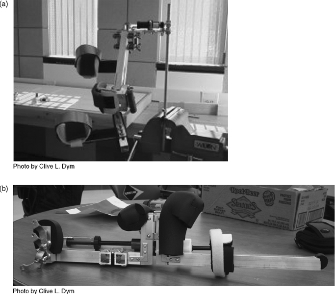
If our part is particularly complex, it may be simpler to use CNC machining to produce it. CNC machines range in size and cost and can produce very small objects or very large objects in a range of materials. These machines use the 3D computer-aided design (CAD) models and/or drawings of your part to create a step-by-step machine log in a software program such as Mastercam™, which is then input into the CNC machine. These machines can achieve much higher tolerances and can produce much more intricate parts than machining by hand.
If we have the option and choose to machine the prototype ourselves, we need to remember that safety in the workshop is critically important. Power tools can easily cause dismemberment and death. A moment's inattention can lead to a permanent change in lifestyle and career. For more details on common machine shop safety practices, see Appendix A.
- Rapid prototyping technologies: Rapid prototyping technologies have emerged in recent years as relatively fast and cheap ways to fabricate prototypes that would otherwise need to be injection molded. Rapid prototyping techniques use 3D CAD models as inputs, and convert these 3D files into thin 2D layers to build the 3D part. Rapid prototyping technologies include stereo-lithography and selective laser sintering, which involve using a laser to harden either a resin bath or a polymer powder in a particular configuration to build each layer.
Another technique is fused deposition modeling, in which a heated filament of a particular material is squeezed out of a tube one layer at a time onto a stage. The stage is then moved down a fixed increment and another layer completed. Fused deposition modeling utilizes standard engineering thermoplastics, most commonly acrylonitrile-butadiene-styrene (ABS), but more than one material can be used at once. Thermoplastics are used to make light, rigid, molded products. ABS is impact resistant and tough, making the parts produced from fused deposition modeling structurally functional. Parts made by this method can be sanded and machined postprinting to finish the part. Most commercial 3D printers using this technology have build resolutions of 0.254 mm (0.010 in), but the latest technology available has a build resolution of 16 microns (0.0006 in) and the capability of using multiple materials to build parts, with material properties ranging from rubber to thermoplastics.
3D printed parts can be very useful for communicating ideas to our client and can be created relatively quickly, but there are some drawbacks. Figure 10.3 shows both a 3D printed version of a screwdriver and its hand-machined counterpart. Both parts were made by HMC students in the design realization component of the E4 design course. The 3D printed version took 4 h to complete, while the machined part can take 15–20 h for a new machinist. The 3D printed version can be very useful for communicating overall size of the design and ergonomic features, such as the depth of the grooves in the handle. However, the printed blade and handle do not fit together, as the print resolution did not meet the required tolerances. In addition, small pieces, such as the pin, are very brittle and can be easily broken. It is easier to achieve specified tolerances by machining a part by hand, and if our tolerances are really tight, we should consider CNC machining.
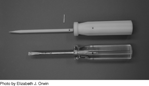
Figure 10.3 3D printed (top) and machined (bottom) versions of the HMC E4 screwdriver. Note that without sanding, the 3D printed blade cannot fit into the handle because of print resolution limits.
10.2.4 How Much Will It Cost?
We will describe some aspects of estimating cost in Chapter 13, but it is worth noting here that it is wise to plan for miscalculations of prices and of the numbers of parts and amounts of materials that we will use. Prices always seem to go up between the time items are priced and the time they are bought. And we often forget to include sales tax and shipping in our costs. So it's good to leave a margin for error, say 10-15%, especially if this is a first-ever model-building project. We should also be careful to ensure that any big-budget items really meet our needs before we order them: A 10% reserve won't help if the $100 item in the $125 budget is the wrong one.
10.3 NOTES
Section 10.2: The definitions quoted at the beginning of this discussion are from Webster's Tenth Collegiate Dictionary (Mish 1993).