Chapter 4. Introducing Microsoft Advanced Threat Analytics
![]() Protecting on-premises resources
Protecting on-premises resources
When enabling enterprise mobility in a hybrid environment where cloud services are integrated with an on-premises infrastructure, you need to ensure that on-premises security controls are in place to protect company data. The problem with security controls that are currently implemented in some environments is the limited protection provided when sophisticated security breaches occur or when a user’s identity is compromised. Although Microsoft Azure Active Directory Premium reports can help to identify suspicious activities around authentication, organizations need to have a mechanism to monitor on-premises resources and mitigate potential attacks.
Microsoft Advanced Threat Analytics (ATA) can help companies identify suspicious user and device activity. By leveraging advanced machine-learning technology, ATA helps identify suspicious user and device activity while providing clear and relevant attack information. This chapter explains this new member of the Enterprise Mobility Suite (EMS) and covers the design considerations that should be taking place before implementing it.
Protecting on-premises resources
Although there is a trend to move resources to the cloud, most environments are still in transition, which means they are in a hybrid mode. While in hybrid mode and adopting mobility, you must be fully aware of your threat landscape. However, being aware is not enough; actions must be taken to mitigate attacks in a world of constantly evolving cyber tactics. IT has to adapt as fast as the attackers. IT needs to identify abnormal behavior and take actions to either mitigate a potential threat or ignore it in cases of expected behavior for their environment. On-premises security becomes particularly important in “bring your own device” (BYOD) scenarios, where users are bringing their own devices to an on-premises infrastructure.
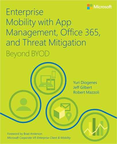
To enhance the security of your on-premises infrastructure, Microsoft includes ATA as part of the EMS solution. The goal is to have an end-to-end solution that carries security considerations for data and user identity throughout the entire communication channel, from the device, to the cloud, and to the on-premises datacenter, as shown in Figure 4-1.
Understanding ATA
Microsoft ATA uses machine learning for analyzing entity behavior. Using deep packet inspection technology, ATA analyzes all on-premises Active Directory network traffic. After analysis, ATA builds an Organizational Security Graph, a living, continuously updated view of all users, devices, and resources within an organization that understands normal network behavior. ATA looks for any abnormalities in the entities’ behavior and raises alerts, but not before abnormal activities have been contextually aggregated and verified.
More Info
For more information about entity relationship behavior, read https://msdn.microsoft.com/en-us/library/gg309412.aspx. For more information about deep packet inspection, read http://www.techrepublic.com/blog/data-center/deep-packet-inspection-what-you-need-to-know.
ATA analyzes the behaviors among users, devices, and resources, and their relationship to one another. It can also detect known attacks. ATA contextually aggregates suspicious activities before alerts are issued. What ATA detects is based on three variants:
![]() Abnormal user behavior, such as anomalous login.
Abnormal user behavior, such as anomalous login.
![]() Malicious attack, such as pass-the-hash. For more information about pass-the-hash attacks, read https://technet.microsoft.com/en-us/dn785092.aspx.
Malicious attack, such as pass-the-hash. For more information about pass-the-hash attacks, read https://technet.microsoft.com/en-us/dn785092.aspx.
![]() Known security issues and risks, such as exploitation of weak protocols.
Known security issues and risks, such as exploitation of weak protocols.
ATA can also collect relevant events from Security Information and Event Management (SIEM) systems or from domain controllers via Windows Event Forwarding (WEF). In summary, the sources of information for ATA are domain controller network traffic, Active Directory itself (via LDAP queries), and Windows event logs (including security event 4776, SIEM, and WEF).
To detect common attacks, ATA parses all the network traffic that comes from domain controllers, and then resolves the entities involved in a logical representation of the traffic. Once this process is done, results are sent to the ATA Center, where the parsed traffic will be stored and all detection engines will be run on the database. ATA adapts to changes, identifies abnormal behavior with its proprietary algorithm, and reports anomalies. Once ATA is deployed on-premises, it continually monitors the on-premises infrastructure to ensure protection based on the following four phases:
![]() Analyze In this phase, ATA uses preconfigured, nonintrusive port mirroring. All Active Directory–related traffic is copied to ATA while remaining invisible to attackers. ATA uses deep packet inspection technology to analyze all Active Directory traffic.
Analyze In this phase, ATA uses preconfigured, nonintrusive port mirroring. All Active Directory–related traffic is copied to ATA while remaining invisible to attackers. ATA uses deep packet inspection technology to analyze all Active Directory traffic.
![]() Learn ATA starts learning and profiling behaviors of users, devices, and resources, and then leverages its self-learning technology to build an Organizational Security Graph. This graph is a map of entity interactions that represent the context and activities among users, devices, and resources.
Learn ATA starts learning and profiling behaviors of users, devices, and resources, and then leverages its self-learning technology to build an Organizational Security Graph. This graph is a map of entity interactions that represent the context and activities among users, devices, and resources.
![]() Detect In this phase, ATA looks for any abnormalities in an entity’s behavior and identifies suspicious activities.
Detect In this phase, ATA looks for any abnormalities in an entity’s behavior and identifies suspicious activities.
![]() Alert If abnormal or suspicious activities occur, ATA triggers an alert. For each suspicious activity, ATA provides recommendations for the investigation and remediation at the ATA Console.
Alert If abnormal or suspicious activities occur, ATA triggers an alert. For each suspicious activity, ATA provides recommendations for the investigation and remediation at the ATA Console.
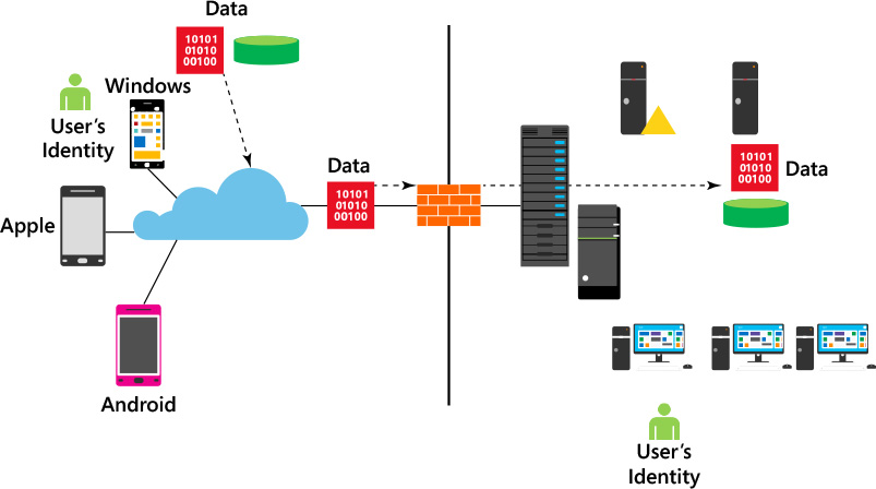
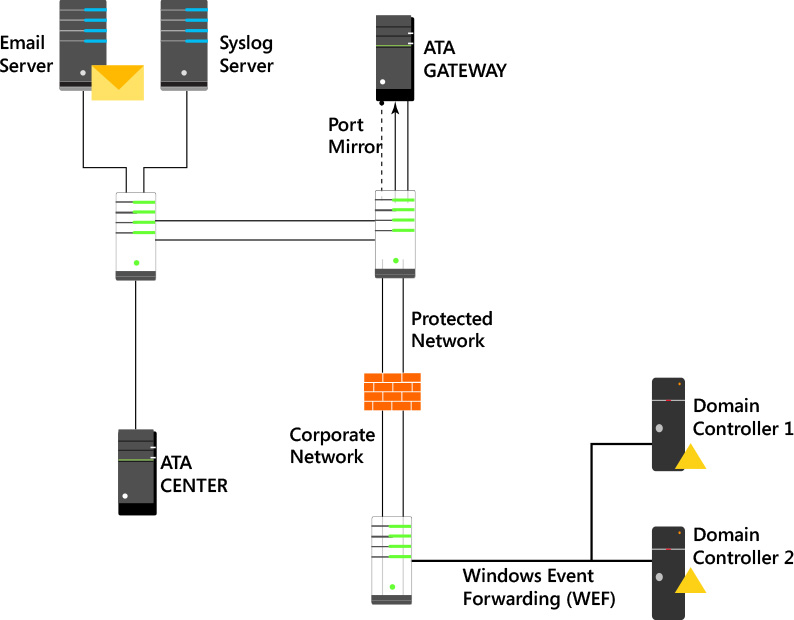
To further increase accuracy and save time for IT administrators, ATA doesn’t only compare the entity’s behavior to its own, but also to the behavior of other entities in its interaction path before issuing an alert. This means that the number of false positives are greatly reduced. To better understand how ATA works, you need to know which components are included in a common on-premises topology. Figure 4-2 shows a standard topology with ATA components.
There are two core components for ATA deployment: the ATA Gateway and the ATA Center. The ATA Gateway is responsible for analyzing network traffic to and from domain controllers, receiving data from entities located in the on-premises domain, receiving information from the SIEM system (if present), and transferring data to the ATA Center. All administration occurs via a web-management interface on the ATA Center, which is responsible for managing the ATA Gateway settings and detecting suspicious activities and abnormal behavior.
Communication between the ATA Center and the ATA Gateway is encrypted using Secure Sockets Layer (SSL) on TCP port 443. For this configuration to work properly, you need to configure two IP addresses on the ATA Center. The ATA Center service will bind port 443 to the first IP address and IIS will bind port 443 to the second IP address. Although you can use a single IP address and configure two different ports, having two IP addresses is the recommended setup.
ATA requires that you configure port mirroring in the network switch where the ATA Gateway is connected with the domain controllers. This requirement is necessary to allow ATA to perform deep packet inspection on traffic to and from the domain controllers to identify known attacks. ATA also uses network traffic to learn which users are accessing which resources and from which computers. In addition, ATA makes LDAP queries to domain controllers to create user and device profiles, using a custom user account that requires read-only access to the domain.
Important
One ATA Center can support multiple ATA Gateways. For more information about sizing, read the “Planning and designing ATA” section later in this chapter.
With ATA, there isn’t a need to create rules, thresholds, or baselines and then fine-tune each at a later time. Approximately three weeks after deployment, ATA starts to detect behaviorally suspicious activities. However, ATA will start detecting known malicious attacks and security issues immediately after deployment.
Deploy ATA in a restrictive communication environment
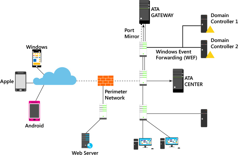
In some circumstances, you might need to deploy ATA in an environment that has a firewall that controls the communication between subnets or even within the same subnet. When the ATA Center and Gateway are in between a network device that filters the communication, such as a firewall, you will need to open ports to allow this communication to take place. The scenario shown in Figure 4-3 has the ATA Center isolated in a protected network. Use Table 4-1 to understand which ports should be open, the direction, and the purpose.
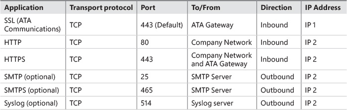
Another common scenario is when the ATA Gateway is located in a network behind a firewall, as shown in Figure 4-4. In this scenario, use Table 4-2 to understand which ports should be open, the direction, and the purpose.
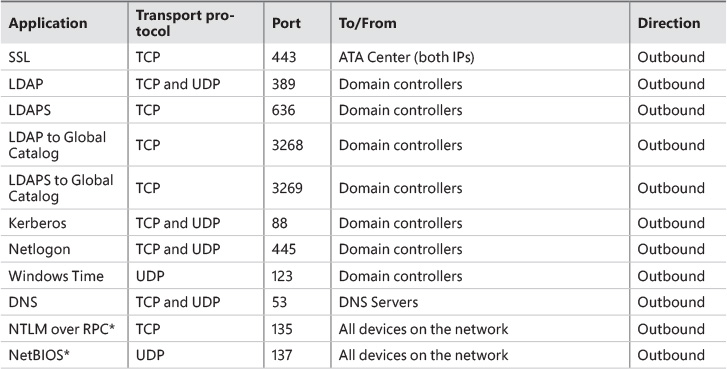
As part of the name-resolution process done by the ATA Gateway, these ports need to be open inbound on devices on the network from the ATA Gateways.
ATA architecture
As mentioned previously, ATA is distributed in two key roles (Gateway and Center). These roles have different tasks to perform, and their core architectures are slightly different. The most complex architecture is the ATA Gateway. Figure 4-5 shows the user-mode elements that are used by ATA Gateway.
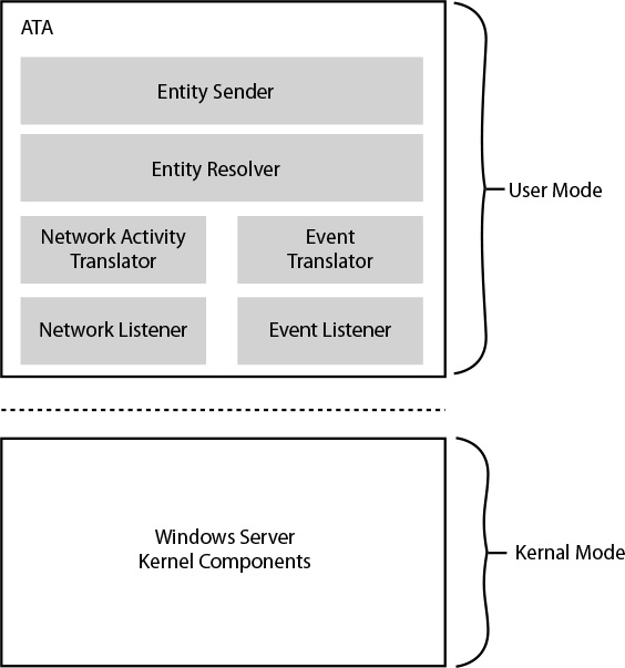
You can see that all core elements of ATA run in user mode and each has a unique task. The following list provides a brief explanation of each element:
![]() Entity Sender is responsible for sending the parsed and matched data to the ATA Center.
Entity Sender is responsible for sending the parsed and matched data to the ATA Center.
![]() Entity Resolver takes the parsed data (network traffic and events) and resolves the data with Active Directory to find account and identity information and match it with the IP addresses found in the parsed data. In addition, the Entity Resolver will also inspect the packet headers, enable parsing of authentication packets for machine names and properties, and identify and combine all these attributes with the data in the actual packet.
Entity Resolver takes the parsed data (network traffic and events) and resolves the data with Active Directory to find account and identity information and match it with the IP addresses found in the parsed data. In addition, the Entity Resolver will also inspect the packet headers, enable parsing of authentication packets for machine names and properties, and identify and combine all these attributes with the data in the actual packet.
![]() Network Listener is responsible for capturing network traffic and parsing the traffic. This is a CPU-intensive task, so you need to plan and design the solution well.
Network Listener is responsible for capturing network traffic and parsing the traffic. This is a CPU-intensive task, so you need to plan and design the solution well.
![]() Event Listener is responsible for capturing and parsing Windows events forwarded from a syslog server (in case one exists in your infrastructure).
Event Listener is responsible for capturing and parsing Windows events forwarded from a syslog server (in case one exists in your infrastructure).
![]() Network Activity Translator and Event Translator are responsible for converting raw network traffic and events into an ATA-logical representation of them.
Network Activity Translator and Event Translator are responsible for converting raw network traffic and events into an ATA-logical representation of them.
Enhance enterprise mobility security with ATA
According to Verizon Data Breach Investigation Report 2013, 76 percent of all network intrusions occur because of compromised user credentials. When users carry their mobile devices and use cloud apps, the threat landscape expands and the likelihood of data being compromised increases. If your company doesn’t have a system that monitors users’ behavior, it will be hard to identify users who are bringing a compromised device on-premises to access resources in the corporate network. Cyber security attacks are evolving, and in some cases it can take up to eight months before a breach is detected.
More Info
For more information, read http://www.verizonenterprise.com/resources/reports/rp_data-breach-investigations-report-2013_en_xg.pdf. Read this article for more information: http://blog.trendmicro.com/catch-me-if-you-can-how-apt-actors-are-moving-through-your-environment-unnoticed/.
ATA closes this gap for the enterprise mobility solution by leveraging all capabilities that were previously explained to identify potential threats. For companies embracing enterprise mobility, this is a critical step toward a safer deployment as employees use different devices and are exposed to more diverse threats. The fictitious company Blue Yonder Airlines (described in Chapter 1, “Understanding Microsoft enterprise mobility solutions”) will leverage ATA to monitor on-premises resources and identify abnormal behavior in the network.
Planning and designing ATA
Because ATA is a product that is installed on-premises, you must be aware of the prerequisites from the infrastructure perspective and from the server-side perspective. You must understand how to properly design the solution prior to deployment to start using it effectively.
Infrastructure considerations
You should review your current on-premises infrastructure prior to deploying ATA. Ideally, you should already have a good understanding of what expected network behavior is, knowing network peak times and the core protocols that are used in transit. From the networking perspective, you need to identify the subnets where the DHCP-managed IP address leasing has a short Time To Live (TTL) duration (seconds or minutes). This is an important consideration because, during the ATA installation, you can make the appropriate changes to the short-term IP address lease configuration to force ATA to reduce the cache lifetime for all IP addresses in that particular subnet (or subnets). This change is key to better accommodating the fast reassignment between devices. Evaluate not only the local area network (LAN) infrastructure, but also virtual private network (VPN) and Wi-Fi networks because usually these subnets have short-term IP address lease durations. Also, make sure to evaluate your network infrastructure to understand where the ATA Gateway and ATA Center will reside.
Before deploying ATA, ensure that your on-premises infrastructure has domain controllers running Windows Server 2008 or later, and that there is a user account created with read access in the domain that will be monitored by ATA. If your organization has an Active Directory infrastructure that has multiple organizational units (OUs) with a different access control list for each OU, make sure this account will have at least read access to all these OUs. Also keep in mind that you can deploy only one ATA instance per forest, even if this forest has multiple domains. If your environment consists of multiple forests, you will need multiple ATA deployments.
Port mirroring must be configured for each domain controller. This step is mandatory so that ATA can see all traffic to and from each domain controller. Each domain controller is configured as the source of the port mirroring, and the ATA is the target. This configuration can be done in a physical or virtual switch.
Important
From the supportability standpoint, some combinations of virtual and physical port mirroring aren’t supported. For more information, read the supported port mirror options in “Configure Port Mirroring” at https://technet.microsoft.com/en-us/library/mt429376.aspx. Also note that you can’t have a domain controller running in Azure Information as a Service (IaaS) because port mirroring isn’t supported there.
You must also take into consideration the number of domain controllers you have and the traffic that will be generated. One ATA Gateway can support multiple domain controllers; however, you must understand your current environment to correctly size the amount of ATA Gateways needed for each domain controller. Use the guidelines from http://aka.ms/atasizing to correctly size your ATA solution prior to deployment.
ATA Center considerations
To install the ATA Center, you must first have a server with Windows Server 2012 R2 (workgroup or in a domain-joined environment) configured with all current operating-system updates. The installation can be done in a physical server or in a virtual machine. The minimum hardware requirements are:
![]() CPU: Eight cores
CPU: Eight cores
![]() Memory: 48 GB
Memory: 48 GB
![]() Storage: 1000 GB per month to monitor two light domain controllers
Storage: 1000 GB per month to monitor two light domain controllers
![]() Network: One network adapter with two IPs
Network: One network adapter with two IPs
You can either install a self-signed certificate during the installation of the ATA Center or install a certificate from an internal or external public Certification Authority (CA) like VeriSign. If you decide to use a self-signed certificate during the installation, you can replace it for another one post installation. The certificate will be used by IIS and for server authentication purposes.
ATA Gateway considerations
From the operating system perspective, the ATA Gateway requirement is the same as the ATA Center. You can install ATA Gateway in workgroup or in a domain-joined environment. However, you can’t install it on a domain controller. The installation can be done on a physical server or a virtual machine. The minimum hardware requirements are as follows:
![]() CPU: Four cores
CPU: Four cores
![]() Memory: Eight GB
Memory: Eight GB
![]() Storage: Enough for the OS + 10 GB for ATA + crash dumps = at least 100 GB
Storage: Enough for the OS + 10 GB for ATA + crash dumps = at least 100 GB
![]() Network: Two network adapters; one for management and one to capture traffic from the domain controller
Network: Two network adapters; one for management and one to capture traffic from the domain controller
Important
The time synchronization between the ATA Center server and the ATA Gateway server must be within five minutes of each other.
Just as we recommended for the ATA Center, here you can also use a self-signed certificate during the installation of the ATA Center or install a certificate from an internal or external public Certification Authority (CA) like VeriSign. If you decide to use a self-signed certificate during the installation, you can replace it for another one post installation.