Chapter 6. Service Containers and Abstract Endpoints
In the next three chapters, we will examine the details of what makes an ESB. The ESB provides an architecture that brings together all the concepts described in previous chapters into an infrastructure that can span an extended enterprise and beyond. The base definition of an ESB provided by Gartner Inc. and discussed in Chapter 1, describes an ESB as consisting of four things: Message Oriented Middleware, web services, intelligent routing based on content, and XML data transformation.
Expanding on the definition from Gartner, we can go into more details of these key components:
Message Oriented Middleware (MOM)
Robust, reliable transport
Efficient movement of data across abstract data channels
End-to-end reliability
Web services
Service Oriented Architecture (SOA)
Abstract business services
Intelligent routing
Message routing based on content and context
Message routing based on business process rules
Business process orchestration based on a rules language such as BPEL4WS (Business Process Execution Language for Web Services)
XML transformation
Based on XSLT and independently deployed service types
The integration fabric that supports all of this requires an infrastructure, which includes the following:
Highly distributed, scalable service containers
Event-driven service invocation
Centralized management of distributed integration configurations
Diverse client connectivity and support for multiple protocols
Seamless, dynamic routing of data across physical deployment boundaries
Unified security and access control model
Distributed configuration and caching of deployment resources, such as XSLT documents and routing rules
Scriptable and declarative environment
Changeable behavior of integration components based on configuration and rules, instead of compiling behavior into code
An ESB provides a loosely coupled, highly distributed approach to integration. It can integrate nicely with applications built with .NET, COM, C#, and legacy C/C++, and can utilize J2EE components such as the JMS, JCA, and J2EE web services APIs. XML standards such as XSLT, XPath, and XQuery provide data transformation, intelligent routing, and querying of “in-flight” data as it flows through the bus. These standards are used together to provide an open-ended, pluggable, service-oriented architecture. This architecture supports both industry-standard integration components as well as proprietary elements through the use of standardized interfaces.
So, just how are all these components tied together, and what makes the ESB approach unique? Perhaps the most distinguishing characteristic of the ESB is its ability to be highly distributed. Many things contribute to making the ESB highly distributed, but the three components that stand out the most are the use of abstract endpoints for representing remote services, Internet-capable MOM, and a distributed lightweight service container.
SOA Through Abstract Endpoints
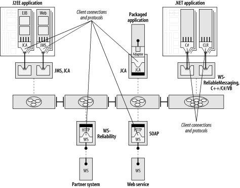
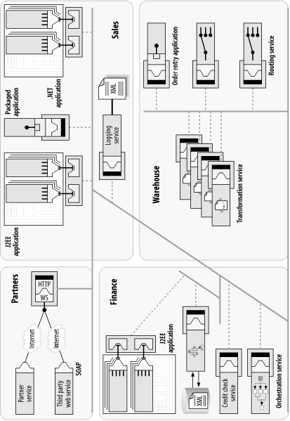
The square boxes in Figure 6-1 represent the applications and services that need to connect to each other and share data through the bus. From the perspective of the integration architect who is assembling services to form a process flow, all applications and services are treated as abstract endpoints. What the endpoints actually represent can be very diverse. An endpoint may represent a discrete operation, such as a specialized service for calculating sales tax. The underlying implementation of the endpoint could represent a local binding to an application adapter, or a callout to an external web service.
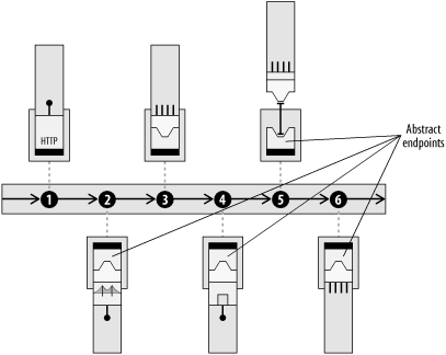
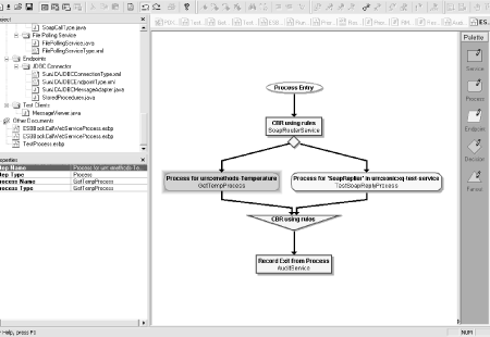
This endpoint abstraction allows an integration architect to use higher-level tools to assemble service endpoints into process flows (Figure 6-2).
An endpoint may represent a single, monolithic application, such as a legacy payroll system. It may represent a suite of applications or an ERP system from an application vendor. It may represent an island of integration from a successful integration broker project. It may represent a whole department or business unit that has a microcosm of its own, yet also needs to link into corporate information channels and share data. It may represent the interface to a business partner with completely separate IT systems.
All service endpoints in an ESB are equal participants in an event-driven SOA, whether the service represents a discrete operation or an interface to an entire ERP suite. From the point of view of the integration architect (you), service endpoints are just logical abstractions of services that are plugged into the bus. The task of building out an integration network involves tying together service endpoints and applying choreography, transformation, and routing rules into process flows between applications. The actual physical locations of the services can be anywhere that is accessible by the bus.
Messaging and Connectivity at the Core
In Figure 6-3, the series of connected rectangles in the center of the diagram represents the core of the ESB. A key component of this core is a highly scalable enterprise messaging backbone that is capable of asynchronously transporting data as messages in a secure and reliable fashion. The messaging backbone supports the asynchronous store-and-forward capability that was discussed in Chapter 5. This messaging core could represent a proprietary MOM, a MOM based on JMS, or a MOM based on WS-Reliability or WS-ReliableMessaging. Or, the messaging core could be a generic messaging engine that supports any combination of these.
The service endpoint provides an abstraction away from the underlying protocol (or MOM channel). The ESB allows the underlying protocol to vary depending on the deployment situation and the QoS requirements. The choice of protocol can vary, from proprietary MOM to unreliable HTTP, to WS-Rel*, depending on the criteria for that leg of the trip and the overall QoS requirements of a message flow. From the perspective of the integration architect who is weaving the fabric of integration, the task is to link together service endpoints into process flows. Using administrative tools supplied with the ESB, the technology behind the endpoint definition and the details of the underlying protocol can be dealt with separately, and can even change over time. It is the responsibility of the ESB to map the high-level process flows into individual service invocations across the designated transport.
Diverse Connection Choices
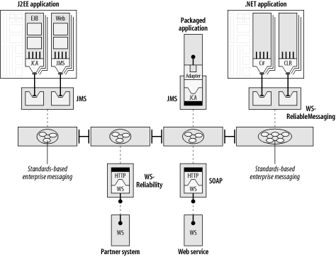
Figure 6-4 highlights some examples of client types and connection points, covering a broad range of options. The middleware at the core must be capable of supporting multiple connectivity choices. Providing a single JMS interface or a proprietary C-based interface is not enough. Diversity in connectivity is a core capability that is fundamental to making the ESB a realistic approach across a global enterprise.
Some large organizations that are in the process of integrating their enterprise have more than 1,000 distinct application types, with more than 10,000 actual instances of applications behind those endpoints. (This is also one of the reasons you need an enterprise MOM at the core.) It is not reasonable to expect that all applications across the board resort to the same interface technology, whether it be web services-based, Java-based, or .NET-based, to participate in an integration environment.
IT departments have too many other things to worry about to go back and significantly retool all their legacy apps. An application that needs to be integrated may be capable only of dumping and loading flat files and transmitting them over FTP. The application may have never been intended to interface with anything, and perhaps was written in C or COBOL. The application may have exposed a low-level, network socket-level interface as part of a one-of-a-kind point-to-point integration project, and can’t otherwise be tampered with. Some of the applications that participate in the data exchange along the bus may reside at a business partner’s site, and may therefore be able to interoperate with your applications only by using SOAP over HTTP. As we will see in Chapter 8, an ESB can even be used as an integration strategy to augment and replace EDI traffic. All of these situations are acceptable because the ESB provides connectivity options or “on-ramps” for each of these approaches.
Because the ESB can support multiple ways of connecting into it, applications don’t require any drastic changes to “get on the bus.” The motto for ESB adoption is “If you can’t bring the application to the bus, bring the bus to the application.” This means that applications should be able to connect into the bus with as little modification as possible. It is the bus, not the applications, that provides the flexibility in connection technologies.
Diagramming Notations
Before going on to discuss the core components of an ESB, it is important to examine some new diagramming notations that are introduced in this chapter. This chapter describes in detail some key concepts of an ESB, and uses a set of glyphs to describe each one. (The Preface to the book goes into an explanation of the history of these glyphs and shows examples of all of them; Chapter 11 will show how these glyphs can be used together to form sketches for integration patterns.) Figure 6-5 depicts a generic ESB endpoint.
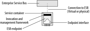
Throughout this book, an endpoint will always be shown as residing inside a service container, the details of which will be explained later in this chapter. There are different types of endpoints in an ESB, each with its own style of representative icon. Figure 6-6 shows how a SOAP or web services endpoint is visualized. Chapter 2 showed one of these in the “Refactoring to an ESB” section.
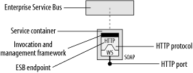
In Figure 6-6, the ESB endpoint that is labeled “HTTP” is an endpoint that uses the HTTP protocol. The HTTP endpoint either exposes a web service interface or acts as a client of a web services interface.
Figure 6-7 shows the icon for an ESB client API endpoint. The client interface exposes methods that an application or service would use to plug into the bus. For a Java client, the application interface would be JMS. For a C++ or C# client, the API would likely mimic the JMS API, but be implemented in either C++ or C#, respectively. For a custom ESB service, there can be a service API that exposes a DOM, SAX, or some other form of interface that treats a service invocation as an inbound SOAP message.
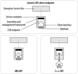
The dashed line between the ESB and the service container is a connection, usually a MOM connection. Note that the C++ client happens to be shown as slightly detached from the endpoint and the service container. This illustrates a separation between the physical implementation of the C++ client and the endpoint. For example, the ESB service container may be implemented in Java, and the C++ client may be hooked into the container using the Java Native Interface (JNI) or via a network layer. The client may also use the native on-the-wire protocol of the underlying MOM directly.
In practice, there may not be a physical container at all. For direct client API connections or protocol connections, the container may be more of an abstract concept than a physical implementation. The container is conceptually part of the bus, and therefore the dotted connection line is a virtual connection in the abstract sense. It may map to an underlying MOM connection in the physical implementation. The endpoint definition and the invocation and management framework could be transparently built into the bus fabric instead of being represented by a physically separate Java, C++, or C# process. These implementation details would also depend on the ESB vendor. The point is that these are representative forms of showing a service container with an endpoint. You, as the integration architect, have the flexibility to choose the appropriate rendition that most closely matches your perspective.
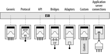
Figure 6-8 shows examples of the various connection types and protocols that an ESB should be able to support. They will be explained in more detail in the next section.
Independently Deployable Integration Services
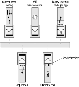
Integration capabilities of the bus are implemented as separate services. Specialized integration services, which can be extended and augmented using a service interface, provide the integration capabilities that allow applications to easily interoperate (Figure 6-9). Examples of such services include:
A specialized transformation service, with the sole responsibility of applying an XSLT stylesheet to convert an in-flight XML message from one dialect of XML to another
A content-based routing service, which applies an XPath expression to look contextually into the nodes of the XML documents as they pass through the service and make determinations on where to send the message next
An XML logging service, which extracts a copy of an XML message as it travels through a portion of a business process and logs it for auditing and tracking purposes
Chapter 8 explores more examples in a case study that uses custom services for EDI translators and SAP adapters.
Because these integration capabilities are themselves implemented as services, they can be independently deployed anywhere within the network. The result is precise deployment of integration capabilities at specific locations, which can then be scaled independently as required. It also means that services can easily be upgraded, moved, replaced, or replicated without affecting the applications that they cooperate with.
The ESB Service Container
The highly distributed nature of the integration capabilities of the ESB is largely due to traits of the ESB service container. A service container is the physical manifestation of the abstract endpoint, and provides the implementation of the service interface. A service container is a remote proces s that can host software components. In that respect, it has some similarities to an application server container, but with the specific goal of hosting integration services.
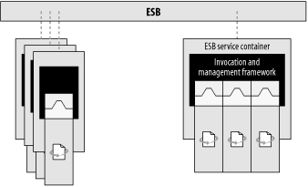
A service container is simple and lightweight, but it can have many discrete functions. As illustrated in Figure 6-10, service containers take on different roles as they are deployed across an ESB.
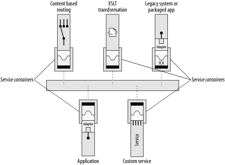
Unlike its distant cousins, the J2EE application server container and the EAI broker, the ESB service container allows the selective deployment of integration broker functionality exactly when and where you need it, and nothing more than what you need. In its simplest state, a service container is an operating system process that can be managed by the ESB’s invocation and management framework.
A service container can host a single service, or can combine multiple services in a single container environment, as illustrated in Figure 6-11.
An ESB service is also scalable in a fashion that is independent of all other ESB services. A service container may manage multiple instances of a service within a container. Several containers may also be distributed across multiple machines for the purposes of scaling up to handle increased message volume (Figure 6-12).
The Management Interface of the Service Container
An ESB service container should handle the inflow and outflow of management data such as configuration, auditing, and fault handling. Management interfaces should be implemented using the Java Management eXtensions (JMX) if the ESB implementation supports Java. A more detailed discussion on the use of JMX in an ESB can be found in Chapter 10.
As illustrated in Figure 6-13, an ESB service container supports the retrieval of configuration data from a directory service, and can also have a local cache of configuration data. This means that even if other parts of the ESB, including the directory service, become temporarily unavailable, the service container can continue to operate with its current set of configuration data.
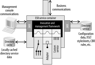
Management input data can originate from a remote management console issuing commands such as start, stop, shut down, and refresh the cache. Management output data can consist of event tracking, such as notification that a message has successfully exited the service or that a failure has occurred. These inputs and outputs can be managed by a JMX management console or redirected to some other management tool using standard protocols such as the Simple Network Management Protocol (SNMP).
The ESB Service Interface
The ESB container provides the message flow in and out of a service. It also handles a number of facilities, such as service lifecycle and itinerary management, that we will explore in a later section. As illustrated in Figure 6-14, the container manages an entry endpoint and an exit endpoint, which are used by the container to dispatch a message to and from the service.
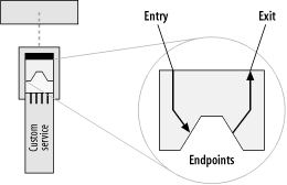
XML messages are received by the service from a configurable entry endpoint. Upon completion of its task, the service implementation simply places its output message in the exit endpoint to be carried to its next destination using the “request/reply” or “reply-forward” pattern discussed in Chapter 5. The output message may be the same message that it received. The service may modify the message before sending it to the exit endpoint. Or, the service may create a completely new message to serve as a “response” to the incoming message and send the new message in the exit endpoint. The following code example shows what a service implementation looks like:
public void service(ESBServiceContext ctx) throws ESBServiceException {
    // Get any runtime process parameters.
    Parameters params = ctx.getParameters( );
    // Get the message.
    ESBEnvelope env = null;
    env = ctx.getNextIncoming( );
    if (env != null) {
        ESBMessage msg = env.getMessage( );
        ... // Operate on the message
    }
    // Put the message to the Exit Endpoint
    ctx.addOutgoing(env);
}
What is placed in the exit endpoint depends on the context of the situation and the message being processed. In the case of a CBR service, the message content will be unchanged, with new forwarding addresses set in the message header.
In more sophisticated cases, one input message can transform into many outputs, each with its own routing information. For example, a custom service can receive a purchase order document, split it up into multiple output messages, and send out the purchase order and its individual line items as separate messages to an inventory or order fulfillment service. The service implementation in this case does not have to be written using traditional coding practices; it can be implemented as a specialized transformation service that applies an XSLT stylesheet to the purchase order document to produce the multiple outputs (if the ESB has an XSLT extension to support multiple outputs).
Auditing, Logging, and Error Handling
Auditing and logging play an important business function within an integration strategy. Part of the reason you want to integrate across a common backbone is to gain real-time access to the business data that is flowing between departments in an organization. A reliable communications backbone will ensure that the data gets to its intended destinations. An auditing framework will allow you to track the data at a business level.
As part of its management capabilities, an ESB container provides an auditing and logging facility. This facility can have multiple sources for tracking data. System-level information about the health of the service itself and the flow of messages can be tracked and monitored. Application-level auditing, logging, and fault handling are accomplished through additional endpoints that are available to each service. As illustrated in Figure 6-15, the service implementation has three additional endpoints at its disposal: a tracking endpoint, a fault endpoint, and a rejected-message endpoint. A service can be created such that a message can be placed in the tracking endpoint in addition to its normal exit destination. A rejected-message endpoint can be used for system-level errors, such as a malformed XML document, or any case in which the service itself throws an exception. The fault endpoint can be used for any application-level errors, or faults, that can occur.
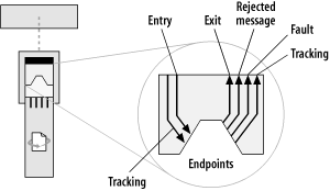
There is an underlying philosophy behind the way tracking, system errors, and application faults are handled. In addition to a normal exit endpoint to handle the outgoing flow of a message, additional destinations are available to the service for auditing the message and for reporting errors. The service implementation has these endpoints available for its own use. From the service implementation’s point of view, it simply places data into the tracking endpoint or fault endpoint, and the surrounding ESB framework takes care of managing the auditing, logging, and error reporting. A tracking endpoint can be configured to point to anything—a topic or queue destination, or even a call to an external web service. This approach provides a separation between the implementation of the service and the details surrounding the fault handling. The implementer of a service need only be concerned that it has a place to put such information, whether it is information concerning the successful processing of good data, or the reporting of errors and bad data.
Tracking can be handled at both the individual service level and the business process level. A business process may make use of different implementations of individual services over time. The tracking of a fault occurrence or the auditing of an individual message can be tied to the context of the greater business process that is utilizing the service at the time.
In Chapter 7, we will explore more about how auditing facilities are used. We will also see that the use of these endpoints is one way of doing auditing and logging with an ESB. Other approaches include placing a specialized XML persistence service in the path of a message in a process flow, which can be much less intrusive to each individual service implementation.
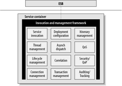
ESB Service Container Facilities
The container is an intrinsic part of the ESB distributed processing framework. In some sense, the container is the ESB—more so than the underlying middleware that connects the containers together. The container provides the care and feeding of the service. As illustrated in Figure 6-16, the ESB container provides a variety of facilities that a service implementation may have at its disposal. Facilities such as location, routing, service invocation, and management are taken care of by the container and its surrounding framework, so the implementation of a service does not have to be concerned with those things. The container also provides facilities for lifecycle management such as startup, shutdown, and resource cleanup. Thread pooling allows multiple instances of a service to be attached to multiple listeners within a single container. Connection management facilities provide the specifics of the binding to the underlying MOM, plus additional fault tolerance and retry logic.
QoP and QoS
Quality of Protection (QoP) and security, Quality of Service (QoS), and transaction services are also provided to the service via the ESB container. Some of these capabilities may be delegated by the service container to the underlying MOM that it is bound to. QoS options, such as exactly-once delivery of messages, are best delegated to a messaging infrastructure that is built for that. If the exactly-once delivery option is dependent on an implementation of a reliable SOAP specification such as WS-Reliability or WS-ReliableMessaging, it would likely still be delegated to a SOAP processor that has MOM qualities such as message persistence, store-and-forward, and duplicate detection.
Administration of ESB facilities
All of these facilities of the ESB container are intrinsically tied to the administrative functions of the ESB, which means that even if you are writing your own custom service, these facilities are assumed to be there and don’t have to be written into the service itself. Generally speaking, this type of “plumbing” is one of the reasons adopting a middleware infrastructure is so appealing. The ESB brings it to the next level by fully delegating this responsibility to the underlying “plumbing.”
In most cases, the container facilities don’t even need to be exposed to the implementation of the service itself. The container facilities by and large represent an agreement between the container and the underlying middleware. Each facility has its own configuration nuances that can be dealt with using an administrative tool that is part of the ESB offering. For example, a QoS setting for exactly-once delivery would be set as an administrative property of a service, not something a coder would do in the API. Of course, the individual capabilities within each of these facilities are likely to vary depending on the implementation from different vendors.
The method of administration of ESB facilities can range from a full-blown GUI to a command-line interface to an administrative API, depending on the implementation. Don’t assume that one administrative method is “better” than another when considering implementations; each has its purpose. A command-line interface can be a good approach for those accustomed to automating processes by building things into scripts. An API is useful when trying to build an ESB into a larger infrastructure that may already have its own set of user interface administrative tools.
Standardizing ESB Container Connectivity
Within the Java Community Process (JCP), the Java Business Integration (JBI) effort is underway to standardize the means by which components plug into an integration infrastructure. For an ESB, this will provide conformity across implementations. More details on JBI can be found in Chapter 10.
Service Containers, Application Servers, and Integration Brokers
I often get asked for clarification on just what the differences are between ESB service containers, an application server container, and an integration broker. This section will point out the main differences.
Adherence to Standards
You can think of the contrast of an ESB versus an integration broker as highly distributed and standards-based versus centralized, monolithic, and proprietary.
A hub-and-spoke integration broker engine includes four main pieces of functionality: application adapters, data transformation, routing rules, and connectivity (Figure 6-17). Today’s integration brokers were built when few standards were available to exploit, and are therefore largely proprietary. Also, as illustrated in Figure 6-17, some integration brokers have bolted on some standard interface technology, such as web services.
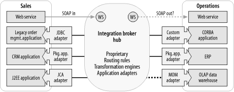
An ESB makes prevalent use of standard interfaces and standard protocols throughout. Integration brokers have been largely proprietary, which, as discussed in Chapter 2, can carry a steep learning curve and result in vendor lock-in. Integration based on standards can provide a number of business benefits beyond just future-proofing your integration strategy. Chapter 3 discusses the benefits of adopting standards throughout your integration projects.
Centralized Hub-and-Spoke Processing
In a hub-and-spoke integration broker, the message payload must travel to the rules engine in the hub to perform data transformations and receive subsequent routing instructions (Figure 6-18). Also, each link into the hub potentially runs over a different protocol and transport, limiting reliability to the weakest link.
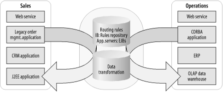
An ESB does not rely on any centralized processing engine, and lets the routing decisions occur at the remote nodes via itinerary-based routing. Hub-and-spoke has the advantage of centralized management and centralized control over routing and transformation rules. However, a good ESB should have a proper distributed management environment that allows remote containers to be updated with fresh information whenever necessary.
What’s Hosted in the Container
To date, the main function of an application server has been to host business logic and to serve up web pages that are often based on dynamic content. Application server vendors trying to get into the integration business have been building integration broker capabilities on top of their application servers.
Both ESB containers and application server containers provide a managed environment for lifecycle issues, instance management, thread management, and timer services. Security and transaction services are also common in most application servers and ESBs.
An ESB service container is intended to host integration services and to execute business process flow logic, and host them only when and where you need them. For example, process flow logic can route an invoice to the proper financial system. Process flow logic can be specified declaratively or written as code in specialized services. Other examples of integration services include hosting an adapter or a content-based router.
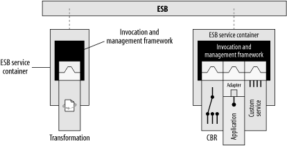
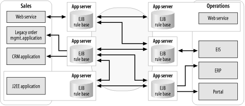
Integration brokers, including those built upon an application server stack, require that the entire IB/appserver stack be installed everywhere you want integration broker functionality (Figure 6-19). Think of what it would mean to install an entire application server at a remote location simply so that it can host a JCA container, which hosts a JCA adapter, which acts as a conduit to an ERP system.
In contrast, with the ESB approach, integration broker capabilities are distributed across a more loosely coupled integration network as integration components that are independently deployed and managed (Figure 6-20). The only software component that needs to be installed at the remote location is the ESB service container. The ESB service container can act as a JCA container directly, without the rest of the appserver or integration broker stack, which in this scenario is just excess baggage. This is one of the business reasons why the ESB is changing the economics of integration. Licensing costs aside, the real cost of deploying application servers everywhere is in the installation, configuration, and ongoing operational overhead and cost of ownership over time.
Management Substrate
Managing an application server, even when using JMX, requires a direct connection between the management console and the remote JMX agent for the application server. In a highly distributed deployment, this separate management connection significantly increases the number of holes that have to be punched through the firewalls (Figure 6-21).
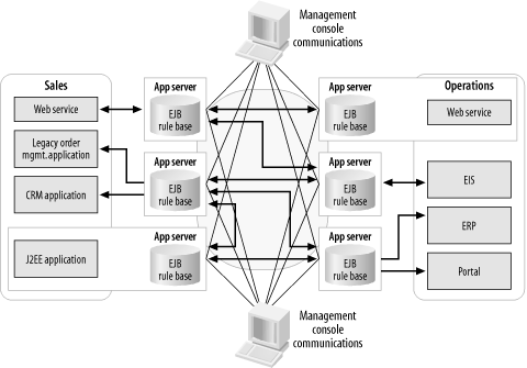
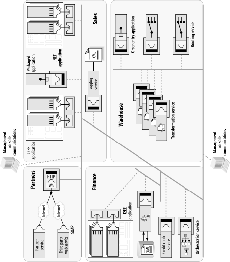
As we’ll discuss in Chapter 10, ESB management traffic is designed to share the bus with application traffic, as illustrated in Figure 6-22. This means that the firewall configuration has to be done only once.
Compiled Class Files Versus Declarative Rules
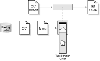
The main benefit of using XML standards (XPath, XSLT, XML DOM, and SAX) for transformation is that it makes the deployed processes much less brittle. For example, as shown in Figure 6-23, an ESB transformation service can be configured and deployed, merely by supplying it with the scripts and parameters it needs to use, as XML documents that are read in from a directory cache. Once deployed, the implementation is remarkably resilient to change in the XML schema. In many cases, changes in the XML schema will not invalidate the XPath selections within the XSLT, and new attributes and elements are carried along by the existing XSL templates. Even if the XSL script does change, it is easily redeployed. More information on service reuse and redeployment can be found in Chapter 7.
In contrast, compiled classes such as XML beans introduce a dependency on the XML schema that obviates adaptation to change. As shown in Figure 6-24, the use of the schema to generate Java code sets in motion a chain of dependencies that must then be retraced every time the schema is modified. This is because schema elements must be bound to Java objects. The problem is further compounded if the transform in question is deployed in multiple locations.
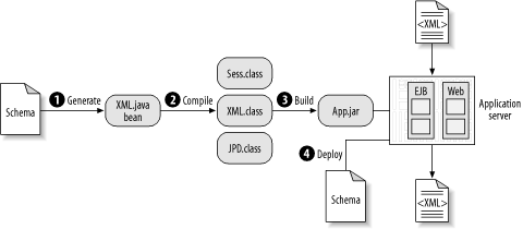
Table 6-1 summarizes the comparison between compiled code in an application server and the declarative functions that are inherent in an ESB.
|
J2EE appserver |
ESB | |
|
Web client proxy |
Session bean* |
HTTP endpoint** |
|
Process definition |
Compiled class (JPD)* |
Process/itinerary** |
|
Deployment parameters |
Bean descriptor** |
DS config params** |
|
Routing rules |
Message bean* |
Routing rules** |
|
Web service call |
WS proxy class* |
WS endpoint** |
|
Aggregation service |
Custom service* |
Process JOIN** |
|
Logging service |
Entity bean* |
XML service** |
|
Transformation |
XML bean* |
Transform service** |
|
Custom service |
EJBean* |
ESB service* |
| * Compiled code |
| ** Declarative artifact |
A key point to note is that the use of dynamically configured parameters, declarative scripts, and other runtime artifacts serves to reduce the amount of compiled code in the system, as illustrated in Table 6-1. The end result is a more flexible, loosely coupled deployment.
Abandon Application Servers?
You shouldn’t take this negatively if you are an adopter of J2EE application server technology. Application servers are an important part of an IT organization, and an ESB is designed to integrate with them very well. In Chapter 11, we’ll see a portal application design pattern in which application servers are used for both the frontend web container display logic and the backend business logic. The ESB is used in the middle to connect the two, providing an integration weave into the rest of the corporate fabric that is not application server-based.
Summary
In this chapter we explored the following:
How an ESB supports an SOA across a series of abstract endpoints. Endpoints can represent applications and services of any size and scope. An integration architect connects endpoints into process flows.
The details of an ESB container as a managed environment for services, and why it is a key component of an ESB architecture.
The comparisons between an ESB container and an application server container.
The next chapter will discuss the concept of itinerary-based routing and the role it plays in enabling a highly distributed SOA across independently deployed services. We will also discuss service reusability and examine some core ESB services, such as content-based routing and XSLT transformation, as well as some advanced ESB capabilities, such as an XML persistence service and an orchestration service.