

OBJECTIVES
103
CHAPTER
6
Requirements
Engineering
n
Define requirements engineering.
n
Discuss the steps of requirements engineering.
n
Describe the details of what to do and how to perform the tasks within
each step in requirements engineering.
n
Analyze several graphical languages that are used during requirements
engineering such as data flow diagrams, use cases, and entity-relationship
diagrams.
91998_CH06_Tsui.indd 103 1/10/13 6:31:23 AM

6.1 Requirements Processing
Requirements form a set of statements that describe the user’s needs and desires. In
developing a software system, these requirements must be clearly and fully understood
by the software engineers who develop the software system. However, we often find
requirements that encroach on the “how” part and enter into
the realm of solution design. Although we should try to limit the
requirements to the “what,” it is not always that clear-cut.
One of the top reasons for software project failures is incom-
plete requirement specifications, as discussed in Chapter 3. At the
same time, one of the important reasons for project success may
be attributed to clear requirements statements. The significance
of user requirements is now well appreciated. Managing require-
ments and user involvement is emerging as a key task in software development, regard-
less of the software development process model.
The following requirements engineering activities are involved in a software
project:
n
Elicitation
n
Documentation and definition
n
Specification
n
Prototyping
n
Analysis
n
Review and validation
n
Agreement and acceptance
Not all of these activities involving requirements are needed to the same degree for
all software projects. How much and when these activities are practiced and in what
sequence is the central theme of this chapter.
6.1.1 Preparing for Requirements Processing
The first step to requirements gathering and requirements engineering is to ensure
that all the preparations are made and that the requirements engineering activities are
planned. The requirements solicitors and the providers must both understand and agree
to a process whether the underlying structure follows an Agile and flexible approach or
a more traditional and rigorous one. A set of preparations, such as those shown in Figure
6.1, must be performed.
Requirements The statements that
describe what the software system should be
but not how it is to be constructed.
Requirements engineering A set of
activities related to the development and
agreement of the final set of requirement
specifi cations.
Figure 6.1 Preparation for requirements engineering.
Plan
for
requirements
activities
Agree on
resources,
process, and
schedule for
requirements
activities
Obtain and
organize the
agreed upon
resources and
process
104 Chapter 6 Requirements Engineering
91998_CH06_Tsui.indd 104 1/10/13 6:31:23 AM

One must first put together a plan for requirements engineering. The plan should
include the following:
n
Process (for requirements engineering) to be used
n
Resources needed
n
Schedule for completing the requirements activities
Depending on the size and complexity of the project, the plan itself may take several
hours to several days or weeks to develop.
Once the plan is drawn, it must be reviewed and agreed upon by all parties involved.
This agreement and commitment to the plan is extremely important because require-
ments are not just an imagination of the software designer or developer. The users and
customers must be involved because requirements represent their needs and desires.
Management must also be involved because resources are required to perform the
activities. The management from both the users’ side and the software development
side must be willing to commit the resources. Finally, the schedule for the requirements
engineering activities must be reviewed and agreed upon by all participants. There have
been situations where prototype development, reviews, and changes to the user inter-
face requirement alone have taken such a significant portion of the software develop-
ment resources and schedule that the project was doomed for a later schedule crunch
and cost over-run. It is sometimes advisable for requirements engineering to keep a fairly
open and flexible schedule. Most of the large enterprises today are experienced enough
to understand that complex projects need to have good requirements, and thus require-
ments engineering itself may be a costly and lengthy effort that should be addressed
separately from the rest of the software project.
After the plan is agreed upon, the resources—from experienced analysts to the
required prototyping tools—must be acquired and brought on board. Finding qualified
requirements analysts may be a time-consuming effort, for a good requirements analyst
must possess multiple talents such as communication skills, special industry skills, and
technical skills. The people involved must also be properly trained on the tools and the
process that will be used in the requirements engineering activities.
For most large software projects, the preparation effort, which may be viewed as
satisfying the entrance criteria for requirements engineering activities, is important and
vital to the success of the rest of the software project.
6.1.2 Requirements Engineering Process
Once the preparation for requirements engineering is completed, the actual require-
ments development may commence. There are many different steps within require-
ments engineering. It is essential to ensure that the planned and agreed-upon require-
ments engineering process is clear to all participants. Figure 6.2 is an example of a
common requirements engineering process.
The process begins with requirements analysts performing the elicitation and gath-
ering of requirements from the users and customers. The gathered information is then
analyzed. During the analysis step, the various requirements statements are checked for
accuracy and conflict, categorized, and prioritized. Even though there is an arrow from
6.1 Requirements Processing
105
91998_CH06_Tsui.indd 105 1/10/13 6:31:23 AM
requirements analysis back to requirements elicitation, there is usually very little oppor-
tunity to continue going back because of the scarce availability of the users who provide
the requirements information. The analyzed material is then processed through three
potential subactivities.
1. Requirements definition and documentation
2. Requirements prototyping
3. Requirements review
Clearly, the analyzed requirements must be properly defined and documented. If nec-
essary, some of the requirements, especially the user-interface aspects, need to be proto-
typed. In large systems, this effort itself may resemble a mini development project. The
defined and documented requirements statements and the prototyped user interfaces
must be reviewed by the users. The users must commit their time and people during the
requirements elicitation and review periods. These three substeps may iterate among
themselves and also with the analysis step. The iterations must be properly managed, or
it will turn into a vicious cycle of schedule and resource consumption.
The last two steps of the requirements engineering in Figure 6.2 involve the delivery
of a finalized requirements specification document. This document must be agreed
upon and will serve as the contract between the customer and the software develop-
ment organization. Once the requirements specifications are agreed upon, they become
the baseline. Thereafter, any modification or change request needs to be controlled and
managed through a change control process to prevent the infamous project scope-
creeping problem, where the project slowly grows in size without anyone’s detection.
Requirements scope-creep may happen any time during the software development
cycle and is one of the worst causes of schedule and cost overrun.
How many of the activities shown in Figure 6.2 need to be performed depend on
the specific software project. Recently, some of the Agile software developers have
mistakenly abandoned a large segment of requirements engineering. On the con-
Figure 6.2 A requirements engineering process.
Requirements
elicitation
Requirements
agreement
Requirements
analysis
Requirements
definition
Requirements
prototyping
Requirements
specification
Requirements
review
106 Chapter 6 Requirements Engineering
91998_CH06_Tsui.indd 106 1/10/13 6:31:23 AM

trary, Agile processes actually recognize the difficulty with requirements changes and
requirements gathering and advocate constant interactions with users to ensure that
the requirements are interpreted correctly. The mistake of not taking the time and
effort to gather and understand requirements can be costly, and it is not advisable for
many good reasons. The following examples of negative consequences that occur if
requirements engineering is not performed illustrate the positive reasons to perform
requirements engineering:
n
There are no documented requirements to base testing on.
n
There are no agreed-upon requirements to control scope-creep.
n
There are no documented requirements to base the customer training or customer
support activities on.
n
It is very difficult to manage project schedule and cost without clear and documented
requirements.
It is thus clear that it is extremely unwise to base software development without any
requirements engineering activities.
At the other end of the spectrum are the excessive costs of efforts devoted to pro-
totypes, reviews, the creation of voluminous documents, and other bureaucratic and
wasteful activities. There are, however, times when the requirements analyst is asked to
develop a requirements specification for the purpose of producing a document called a
request for proposal (RFP) for inviting software development bids from many different
software suppliers. In the case of creating an RFP, requirements analysts are often found
to err on the side of overengineering. Most of the time, we need to be performing some-
where between these two extreme ends of the spectrum.
6.2 Requirements Elicitation and Gathering
Many software engineers start their careers in coding, designing, or testing a software
system. Only a few of them become requirements analysts after they have acquired
some business and industry domain knowledge. The majority of requirements analysts
come from the business side with good industry domain knowledge and good commu-
nication skills. Some experienced user/customer support personnel have also progressed
to attain the position of requirements analyst. Both communication skills and industry
domain knowledge are important in eliciting user requirements. Communication skills
are needed because users/customers do not always know how to state their needs
(Tsui 2004). The requirements analyst must be a good listener and interpreter. It is also
essential that the analyst possesses industry domain knowledge because each industry
often has its own unique terminology. For example, the medical and health industry
has a vocabulary that is distinctively different from that of the aerospace industry or the
financial industry. In order for requirements analysts to function successfully and be able
to properly solicit requirements, they must be well experienced in the specific industry.
Users and customers are often intimately involved in the development of software
and are continually clarifying the requirements, as we saw in Chapter 5, where Agile
processes were discussed. This mode of operation has worked well for small software
projects. However, it is impractical to expect the users and customers to be in constant
6.2 Requirements Elicitation and Gathering
107
91998_CH06_Tsui.indd 107 1/10/13 6:31:23 AM

communication with the developers for large, complex, and lengthy software projects.
We will always need the experienced, subject matter expert requirements analysts for
large projects because of the limited availability of the knowledgeable users.
There are two levels of requirements elicitation. At the high level, the requirements
analyst must probe and understand the business rationale and justification for the
software or the software project. At the low level, the requirements analyst must elicit
and gather the details of the users’ needs and desires. In either case the requirements
analysts must be prepared to conduct the elicitation and gathering. They must have a
set of organized questions to ask the users. The actual elicitation may be conducted in
several modes:
n
Verbal
n
Written (preformatted form)
n
Online form
Both written and online forms force the requirements analyst to have thought
through the questions and enforce some discipline in the preparation. However, ask-
ing users to fill in preformatted forms can be too rigid. Thus a verbal follow-up is highly
recommended. The personal and direct contact with the users will often trigger good
follow-up questions and will also allow users to expand on their input. Throughout all
the elicitation and gathering process, the requirements analyst must be patient, listen
carefully, and ask for more information when needed—vital skills during this phase.
Listening is especially difficult for some requirements analysts, who tend to be more
outgoing and assertive.
The requirements analyst should also gather existing information that is available
in the business process document, business and technical policy document, previous
system manuals, and so on. The requirements for the new software or software project
can often be clarified and explained by information gathered in the past. Reading and
analyzing existing documentation is another necessary skill that requirements analysts
should possess.
6.2.1 Eliciting High-Level Requirements
At the high level, the requirements analyst will need to seek out the management and
executives who sponsored the software project to understand the business rationale
behind it. The business rationale translates into requirements in the form of constraints
on the software product and software project. The category of information that contrib-
utes to this high-level business profile includes the following:
n
Opportunity/needs
n
Justification
n
Scope
n
Major constraint
n
Major functionality
n
Success factor
n
User characteristics
108 Chapter 6 Requirements Engineering
91998_CH06_Tsui.indd 108 1/10/13 6:31:23 AM

Opportunity and needs state what high-level problems the software suppliers have
been brought in to address. This is usually a business-oriented problem rather than a
purely technical problem. For example, the customer may have too high an inventory
or may be losing 50% of customer orders due to poorly managed paper documents. To
solve the problem, the customer needs a solution that may or may not include software
but will usually involve a cost. In order to justify the solution and the cost, there must
be some type of business payback. The requirements analyst in our inventory problem
example needs to find out how high the inventory is. The customer may state that there
is $2 million of extra inventory, and that is too high for them. The customer may also state
that their customer orders need to increase by 30% above the current number. These all
translate to justifications for the software project that is about to be commissioned by
the customer.
The customer may have other issues and problems but states that the aforemen-
tioned inventory and customer orders are the two top problems that need to be solved
as soon as possible. These statements establish the limits and scope of the software
project. In this case, inventory control and order processing are the scope and become
the areas for major requirements.
The requirements analyst must also understand any major constraints. One of the
major ones is likely to be the allotted budget for the software project. The project
budget is usually proportional to the business problem—in our example, the $2 mil-
lion in excess inventory. Information on budget constraints is important when detailed
requirements are being prioritized, and it contributes to the decision process of what is
needed versus what is nice to have. Another major business constraint is the schedule.
Although business executives understand that systems cannot be built overnight, their
needs are always immediate. The implications of schedule constraints and the actual
schedule must be clear to the requirements analyst.
It is vital to have a list of what the customer and the business executives perceive as
the major functionality the new software will be delivering. In the inventory and order
processing example, the major functionality to be delivered may be as follows:
n
Improved inventory control via automating order and shipping processing
n
Online customer order
n
Online delivery/shipping control
Although more-detailed functional requirements must be elicited, these high-level
statements put the proper customer expectations in place. They also facilitate high-level
scoping of the software project and direct the requirements-gathering attention to the
proper area of the business.
The success factor of the software project goes back to the opportunity and needs
that were stated earlier. The software project, upon completion, must resolve the prob-
lems stated in the opportunity and needs. In this example, it must be able to reduce the
inventory carried to less than before. It must also not lose customer orders. Furthermore,
if these goals must be met within the next year, then the software system must be com-
pleted far before next year to allow time for training the users and for actual usage of
the system by the customer, who must have time to utilize the system long enough to
6.2 Requirements Elicitation and Gathering
109
91998_CH06_Tsui.indd 109 1/10/13 6:31:23 AM

experience any of the benefits. The requirements analyst must be able to translate this
into a schedule requirement that the system must be up and running by a certain date.
Oftentimes, the executives and paying customers are not necessarily the day-to-day
users of the system. The success of the system depends heavily on how well these users
are trained. Thus it is imperative to gather and analyze a user profile, which should
include the person’s job title and formal responsibilities, job activities, education and
experience levels, and technical competence.
These high-level business-related requirements are essential to the overall success
of the software project, and they can be used as a source for formulating the high-level
project goals. The requirements analyst should turn these high-level requirements into
high-level goals during the later analysis stage, and then have them reviewed and agreed
upon by all constituents. Even when a few detailed requirements may be misplaced, the
project is often deemed a success if the high-level business goals are met.
6.2.2 Eliciting Detailed Requirements
Once the high-level requirements are gathered, the detailed requirements must be
elicited. During this activity, some of the more technically savvy requirements analysts
should be brought in. While the requirements discussions should, in principle, stay above
the actual implementation and only address what is needed, often the users will venture
into a discussion of how to solve a particular problem. If a software system already exists,
the users will often base their discussion of requirements on that currently existing sys-
tem. Often during these requirements-gathering engagements, both the requirements
analyst and the users may enter into imaginative and technical conversations.
Again, as in high-level requirements solicitation, there needs to be preplanned infor-
mation that should be elicited. At the detailed level, it is so easy to engage in a lengthy
discussion on a specific topic and lose control. There are six main categories of informa-
tion that must be addressed, shown in Figure 6.3, as dimensions of requirements.
Figure 6.3 The six dimensions of requirements.
Business flow
Requirements
Individual functionality Data, formats, and information needs
Systems with other interfaces
User interfaces
Other constraints such as performance,
reliability, and security
110 Chapter 6 Requirements Engineering
91998_CH06_Tsui.indd 110 1/10/13 6:31:23 AM

Individual functionality is the most obvious group and is usually the natural starting
point of requirements elicitation. The requirements analyst is asking the users and cus-
tomers what their problems are in terms of what functions need to be performed. For
example, a functionality need for a payroll area may be initially stated as “there is a need
to provide direct deposit payroll to the financial institution of the user’s choice.” In this
case, direct deposit is a functionality requirement.
Functionality by itself is not enough; it must be explained in the context of the busi-
ness flow or in the context of how the users’ perform their tasks. For example, a function-
ality such as online purchasing needs to be described in the context of specific goods
such as airline tickets. This same online purchasing functionality placed in the business
flow context of purchasing corporate equities may require a slightly different set of steps.
Thus business flow is an important category of information that must be gathered at the
detail-requirements information level. This is similar to the notion
of developing use cases in object-oriented methodology where
the functionalities are performed by actors within some business
context called a scenario; see Schneider and Winters (1998) for
more details on use cases.
Another category of requirements that must be collected at the detail level is the
information pertaining to data and data formats. At the minimum, there must be some
discussion of the application’s input and output data. What is the information that
needs to be entered into the system and for what purpose? If the entered data follow
some business process flow, then that flow should also be described. If there are data
that serve as input for some processing, those must also be described. For example, in
payroll processing, the federal and state tax rules may be bought in a file form. These
tax rules, as a purchased input file, still need to be described. The output data provide
additional information and come in several forms. One is the result of a query. The for-
mat of the query response must be defined. The other is a report. Each report format
needs to be clearly defined. In addition to these application data, there is the applica-
tion system’s information such as error messages or warning messages. Included in
this last category of application system’s information is the help text. There should be
a statement of how much help text is needed. This description of data touches upon
the next category, user interfaces.
How the input and output of a software system is presented falls in the domain of user
interfaces. Today’s software interfaces are mostly graphical in nature. Still, different users
have their unique preferences. For example, both radio button and drop-down window
may be used for logical “exclusive-or” types of choices, and the users’ personal or busi-
ness preferences may dictate one versus the other. Thus the requirements statements
must be clear on the icons used for the interfaces. The flow of the software application
is also a user interface, and it usually mimics that of the business flow. However, there
are times the software needs to purposely differ from the existing business flow because
the software system is meant to improve the current business process. The user interface
requirements, both the look and the flow, are often captured by prototyping the inter-
face. The users are then asked to review and comment on the prototyped interfaces.
Besides interfaces with users, there are other interfaces such as those with an existing
application or to a network system. These interfaces must be clearly identified. In many
situations, the existing system interface already has many clients tied to it. In such cases,
Use case A sequence of actions that a
system should perform within the business
flow context of the user or the actor.
6.2 Requirements Elicitation and Gathering
111
91998_CH06_Tsui.indd 111 1/10/13 6:31:24 AM

the requirement statements should not only describe the interface but also indicate the
likelihood of future changes. There are several dimensions to such an interface:
n
Transfer of control (evocation of the interface)
n
Transfer of data (directly or through a database)
n
Receipt of responses (success or failure, error types and messages)
n
Retry capabilities
The most often forgotten portion of the interface is the description of errors and error
messages along with the respective recovery and retry methodologies.
The last group of requirements addresses issues such as reliability, performance, security,
and adaptability. This category serves as a catchall group and acts as a prompter for all the
nonfunctional requirements that are important to the software project. In large transaction-
oriented applications, it is imperative that a performance requirement on transaction rate
be specified. In life-threatening applications, the reliability and the availability parameters
must be defined in the requirement statements. Availability addresses the system being up,
and reliability addresses the issue of it functioning properly without defect and according to
specification. In large financial applications or communications applications, the protection
of the data and the protection of the transmission of the data are of paramount significance.
For these applications, the requirement statements must address the issue of security. Each
of these requirements or constraints on the software may be applied to a deeper and more
specific level. For example, the requirements statement may specify an acceptable response
time of a user query of product choices in a web-based retail application. There may be
other constraints such as transportability or maintainability that should all be described in
this category. In addition, there may be requirements related to the software project rather
than to the product. The customer may request that the software be written in a certain
programming language or with a certain tool because the customer is considering future
modification of or support of the software product themselves.
6.3 Requirements Analysis
Even after the requirements are elicited and collected, they are still just an unorganized
set of data. They must still be analyzed. The analysis of the requirements consists of two
main tasks:
1. Categorizing or clustering the requirements
2. Prioritizing the requirements
There are many ways to categorize requirements. In clustering and grouping require-
ments, it is important to look for consistency and completeness. We will discuss several
approaches to analysis and categorization of requirements. The methodologies all evolve
around business and usage flow.
6.3.1 Requirements Analysis and Clustering by Business Flow
The requirements may be grouped in many ways. One of them is, in fact, categorizing
them by priority, which will be discussed later. A natural clustering of requirements may
follow the six dimensions of requirements that were discussed earlier:
1. Individual functionality
2. Business flow
112 Chapter 6 Requirements Engineering
91998_CH06_Tsui.indd 112 1/10/13 6:31:24 AM

3. Data, formats, and information needs
4. User interfaces
5. Interfaces with other systems
6. Constraints such as performance, reliability, and security
These categories are not always mutually exclusive. At times there may be some
overlap. For example, under the category of constraints, there may be a requirement
addressing reliability in the form of back-up recovery speed. In the individual func-
tionality group there may be a requirement describing the need for back-up recovery
function. During the analysis time, an overlap such as this example must be clarified
so that there is no duplication. Each requirement must be labeled so that it is uniquely
identifiable and traceable. A simple categorization scheme may be devised for the six-
dimensionality by utilizing a prefix and a number as shown in Table 6.1.
The prefix identifies the category or the dimension of the requirements. When analyz-
ing the requirements, it is best to start with the business flow category. Pick a business
flow first. Assign it the first number, such as BF-1, then associate all the functionality
requirements and number them IF-1.x. The additional x may be used if there is more
than one functionality related to the workflow. In Table 6.1, there are three functionality
requirements, IF-1.1, IF-1.2, and IF-1.3, related to the business flow, BF-1. The data and
their respective data formats related to BF-1 are numbered the same way with DF-1.x.
There are two data requirements related to BF-1 in the table, and there are two user-
interface requirements related to BF-1. There is one system interface requirement and
an additional constraint requirement related to BF-1. The numbering scheme of all cat-
egories is tied to business flow.
Given a business flow, BF-n, there may not be a requirement in the other five catego-
ries related to this business flow. For example, there may not be any further constraint. In
that case there will not be an FC-n. A particular requirement in some nonbusiness flow
category, such as a data requirement, may belong to more than one business flow require-
ment. That is, there may be a DF that is related to two business flows, BF-x and BF-y. The
question is whether this DF should be labeled as DF-x or as DF-y. During the analysis of
requirements, we have to determine which one of the two business flows uses the data for
its primary purpose. The DF will take on the number of the BF that utilizes it for its primary
purpose. In the event the DF is equally important to both business flows, then it will take
on the number of the business flow that first utilizes it. The requirements analysis method-
ology here is based on clustering the five categories of requirements around the business
Table 6.1 Requirements Categorization Scheme
Requirement Area Prefix Requirement Statement Numbering
Individual functionality IF IF-1.1, IF-1.2, IF-1.3, IF-2.1
Business flow BF BF-1, BF-2
Data and data format DF DF-1.1, DF-1.2, DF-2.1
User interface UI UI-1.1, UI-1.2, UI-2.1
Interface to systems IS IS-1
Further constraints FC FC-1
6.3 Requirements Analysis
113
91998_CH06_Tsui.indd 113 1/10/13 6:31:24 AM

flow requirements. The obvious question is what we should do if we have a requirement
that does not easily fit any business flow. One way is to have a designated null business
flow and have all the “misfit” requirements grouped with the null business flow. The num-
bering scheme is just a way to make the association of five categories of requirements
to each business flow. Thus business flow must be included in the discussion during the
requirements elicitation stage. Otherwise, these five categories of requirements will be
grouped by some artificial or conjectured business flow. This methodology of keying
on business flow as the principle requirement is similar to the object-oriented use case
methodology.
6.3.2 Requirements Analysis and Clustering with Object-Oriented Use Cases
Object-oriented (OO) use cases are utilized to describe the requirements of a system.
They are also used for the analysis of requirements and contribute to the design and
testing of the system. A use case is fundamentally a depiction of the following require-
ment information:
n
Basic functionality
n
Any precondition for the functionality
n
Flow of events, called a scenario, for the functionality
n
Any postcondition for the functionality
n
Any error condition and alternative flow
In developing OO use cases, the requirements elicitation and analysis are mingled
together. Once the information is collected, the requirements analysis portion has sev-
eral steps, starting with identification of system boundaries.
The term system here means the product that is to be developed may include both
hardware and software. The identification of system boundaries starts with the delin-
eation of what is included and excluded from the system but may still be needed for
interfacing with the system.
OO utilizes the word actors—an unusual term that refers to all external interfaces with
the system. Figure 6.4 presents a graphical representation of an actor. The modeling lan-
guage used by OO, as stated in Chapter 4, is Unified Modeling Language (UML). The actor
Figure 6.4 A graphical representation of an actor in Object Oriented terminology.
114 Chapter 6 Requirements Engineering
91998_CH06_Tsui.indd 114 1/10/13 6:31:24 AM

symbol of a human stick figure is just a part of the UML notation. A copy of UML may be
obtained from the Object Management Group, which is a nonprofit computer industry
consortium (see the Suggested Readings section at the end of this chapter).
Examples of actors include users of the system, other systems, hardware, network,
and operators. Each actor takes on a certain role with regard to interfacing with the sys-
tem. To identify these actors, which are external to the system but interface with it, the
requirements analyst should ask the following questions:
n
Who uses the system?
n
Who operates and maintains the system?
n
What other systems use this system?
n
What other systems are used by this system?
Some examples of actors may be the user of an order shipping system and an external
system that interfaces with it. They might be described as follows:
n
Shipping clerk: A user of the system who packages the customer-ordered items, places
ship-to address labels, ships the ordered items, and tracks the delivery of the ordered
items.
n
Customer order system: An external system that processes customer orders and pro-
vides customer order information to the order shipping system.
After identifying the external system, the next step in the use-case analysis is to iden-
tify all the activities related to each of the actors. These activities are the things that the
actors want the system to perform and become the use cases. Thus each actor is related
to a set of use cases. The listing of the use cases is the process of identifying what is inside
the system. That is, the use cases will define the requirements of what the system must
perform. An example from the order shipping system use case described at a high level
would be as follows:
n
Shipping label processing: Upon request from the shipping clerk, process the ship-to
address from the customer order system database and print the delivery address on
the special label.
n
Shipping item list processing: Upon request of the shipping clerk, the ordered items list
is processed from the customer order system database and printed out in duplicate
copies, one to be included in the customer package and the other kept as a record.
We can group the order shipping system requirements with its use cases and actors
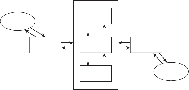
using UML notation, as shown in Figure 6.5. Note that the two actors, shipping clerk and
customer order system, are depicted by the human stick figures, and they are outside
of the rectangular box. The two earlier described requirements as use case statements,
shipping label processing, and shipping item list processing, are depicted as oval-shaped
figures inside the rectangle. The rectangle represents the system. In this case, the rect-
angle represents the shipping system. The boundaries of the rectangle stand for the
shipping system boundaries. While the use cases are depicted at a high-level form in
Figure 6.5, the details of each use case may be further specified in a separate form with
additional UML notations. We will not go into the details of the UML notations here. We
6.3 Requirements Analysis
115
91998_CH06_Tsui.indd 115 1/10/13 6:31:24 AM

have demonstrated how the requirements can be stated in use-case form, grouped, and
related to the actors.
During the requirements analysis phase, we might ask further questions about the
system boundary. For instance, in processing shipping labels, should the shipping clerk
also worry about the weight and the resulting shipping cost? If so, is weighing the items
a manual step to be handled by the shipping clerk outside of the order shipping system,
or should the order shipping system include an automatic weight calculation and cost
computation functionality? Performing system boundary analysis as a part of the require-
ments analysis can further improve and firm up the completeness of requirements.
In OO use-case methodology, the steps of identifying the following factors serve as a
good requirements analysis methodology:
n
Actors
n
Related use cases
n
Boundary conditions
Even though use cases are further expanded on later with details on preconditions,
postconditions, activity flows, alternate paths, and error processing to help the design of
the system, the use cases specified during the requirements phase describe only what
the system needs.
6.3.3 Requirements Analysis and Clustering by Viewpoint-Oriented
Requirements Definition
Viewpoint-oriented requirements definition (VORD) is a requirement analysis method
based on the understanding that requirements are not viewed the same by all the differ-
ent stakeholders. The customers who pay for the system often
have a different perspective on requirements than those who
interface with the system on a daily basis. For a large, complex
system that has many subcomponents, the different users will
articulate the requirements with varied emphasis and diverse
Viewpoint-Oriented Requirements
Definition (VORD) Both a requirements
elicitation and a requirements analysis
methodology.
Figure 6.5 Use-case notation in UML.
Shipping
label
processing
Shipping
item list
processing
Shipping clerk Customer order system
116 Chapter 6 Requirements Engineering
91998_CH06_Tsui.indd 116 1/10/13 6:31:24 AM

specifics. For example, with today’s large enterprise resource planning (ERP) systems,
there are several major components including financial, human resource, planning, and
inventory. The financial person using the system will provide requirements with the
financial lingo and an emphasis on finance. The human resource person will have
another perspective, using the human resource termin ology and having a bias toward
human resources.
Sometimes the same requirement is stated in such different forms and context that they
seem to be different requirements. Other times, the different requirements overlap so much
that they should be reorganized and combined in a totally different way. The key is that there
are many stakeholder viewpoints to the requirements. The disparate viewpoints often result
in distinctly different perspectives of the same problem and they are used to help categorize
and structure the requirements. The VORD methodology is divided into four steps:
1. Identify the stakeholders and the viewpoints.
2. Structure and categorize the view points, eliminating duplication and placing
common ones together.
3. Refine the identified viewpoints.
4. Map the viewpoints to the system and the services that the system is to provide.
For more extensive descriptions and details on VORD, see Sommerville (2004) and
Sommerville and Sawyer (1997).
6.3.4 Requirements Analysis and Prioritization
Categorizing and clustering requirements is only a part of an analysis that enables us to
identify inconsistencies across groups of requirements and possible incompleteness in
requirements. An additional problem is that many times all the identified requirements
cannot be developed and delivered due to constraints such as the following:
n
Limited resources
n
Limited time
n
Limited technical capabilities
As a part of the requirements analysis tasks, we need to prioritize the requirements
so that the higher priority ones are developed and released to the customers first. Often
a multirelease software product is planned out over several quarters or even years by
prioritized requirements. Establishing the priority of the requirements may be based on
many criteria, including the following:
n
Current customer demands
n
Competition and current market condition
n
Future customer needs
n
Immediate sales advantage
n
Critical problems in the existing product
The requirements analysts usually perform the prioritization task with the help of
many other people in the organization. Sometimes the customers and industry experts
are also brought into the prioritization discussions. Much of the software requirements
prioritization is performed with experienced people and customers using an informal
6.3 Requirements Analysis
117
91998_CH06_Tsui.indd 117 1/10/13 6:31:24 AM

approach where the most persuasive or vocal people can bias the priorities of their
favorite requirements. Although this approach is not perfect, it is far better than not
prioritizing and trying to include everything. A typical requirements prioritization list is
shown in Figure 6.6.
A requirements priority list is more like a table and includes multiple columns of
information. It starts with a requirements number, then a brief description of the require-
ment itself is provided. The source of the requirement is important for the planners. The
assessed requirement priority, along with the source of that requirement, contribute to
the decision of whether a particular requirement is included in the current release, next
release, or some future release. This informal approach is frequently used, but often pro-
duces suboptimal results.
A more methodical approach is to pair the requirements and compare their values
in pairs, as proposed by Karlsson and Ryan (1997). This approach, called the analytical
hierarchy process (AHP), places more rigor into the requirements prioritization process
and is often bypassed by the more marketing-oriented people. Each requirement is com-
pared with each of the other requirements in a pairwise fashion. An “intensity value” is
assigned to this relationship. The requirement with the highest overall intensity values
will essentially be the highest priority requirement. The requirement with the next high-
est overall relative intensity value will be the next highest priority requirement and so on.
An example of AHP will clarify this approach.
Consider the situation where there are three requirements, R1, R2, and R3. The scale,
or intensity value, for comparing the pairs of requirements is set from 1 through 9. Given
a pair of requirements, (x, y), the intensity value is considered to be 1 if x is deemed to
be of equal value to y. It is 2 if x is a little more valuable than y and so on until 9, where
x is deemed to be extremely more valuable than y. For our example, consider the matrix
shown in Table 6.2 as the representation of the pairwise value.
In this example, requirement 1 is equal in value to itself; thus the intensity value is
1 for the (Req1, Req1) pair. Requirement 1 is deemed three times more valuable than
requirement 2, and the intensity value for the (Req1, Req2) pair in row 1 column 2 is 3.
*Priority may be 1, 2, 3, or 4, with 1 being the highest.
Figure 6.6 Requirements prioritization list.
Requirement Brief Requirement Requirement Requirement Requirement
Number Description Source Priority* Status
1
2
One-page query
must respond in
less than 1 second
Help text must be
field sensitive
A major
account
marketing
representative
Large account
users
Priority 1
Priority 2
Accepted for
this release
Postponed for
next release
118 Chapter 6 Requirements Engineering
91998_CH06_Tsui.indd 118 1/10/13 6:31:24 AM

Requirement 1 is valued at five times that of requirement 3 as the table shows. When we
visit the pair (Req2, Req1), the value is just the reciprocal of that of the pair (Req1, Req2)
as shown in row 2 column 1. The intensity value is 1/3, which is the reciprocal of 3.
We next calculate the sum of each column in Table 6.2 and then divide each element
in the column in Table 6.2 by the sum of that column. The resulting normalized matrix is
represented in Table 6.3.
We now sum up each of the rows. The sum of row 1, representing requirement 1, in the
normalized table is 1.92. The sum of row 2 is 0.47, and the sum of row 3 is 0.61. Because
there are three requirements in all, each of the row sums will be divided by 3. The results
are 1.92/3 = 0.64 for requirement 1, 0.46/3 = 0.15 for requirement 2, and 0.61/3 = 0.20 for
requirement 3. These three values for the three requirements now represent the relative
values of the requirements. That is, requirement 1 carries 64% of the total requirements
value, requirement 2 carries 15% of the total requirements value, and requirement 3 is
worth 20% of the total requirements value. This provides us with a prioritization scheme
of requirements with the following weights:
n
Requirement 1: 64
n
Requirement 3: 20
n
Requirement 2: 15
Requirement 1 has the highest priority and the most weight, followed by requirement
3 and then requirement 2. The AHP-based pairwise value prioritization scheme forces
us to look at the details of requirements by pairs and may not be practical when we are
dealing with tens of thousands of requirements. It is, however, a reasonable scheme for
prioritizing a small number of requirements.
The prioritization of requirements may sometimes be considered as a classification
scheme, as well. It helps us to classify or prioritize which requirements will be imple-
mented and released when.
Table 6.2 A Pairwise Comparison Matrix
Req1 Req2 Req3
Req1 1 3 5
Req2 1/3 1 1/2
Req3 1/5 2 1
Table 6.3 A Normalized Pairwise Comparison Matrix
Req1 Req2 Req3
Req1 .65 .5 .77
Req2 .22 .17 .08
Req3 .13 .33 .15
6.3 Requirements Analysis
119
91998_CH06_Tsui.indd 119 1/10/13 6:31:24 AM

6.3.5 Requirements Traceability
Although we have mentioned the need for requirements traceability, we have not elabo-
rated on the reason. There are several reasons to ensure that requirements are traceable.
The most significant is the ability to track back after development and verify that all
requirements have been developed, tested, packaged, and delivered. It is also important
to be able to account for anything extra that is not traceable back to the requirements.
There should not be any functionalities or properties that are unaccountable. Kotonya
and Sommerville (1998) have listed four types of traceability:
1. Backward from traceability: Links the requirement to the document source or the
person who created it.
2. Forward from traceability: Links the requirement to design and implementation.
3. Backward to traceability: Links design and implementation back to the require-
ments.
4. Forward to traceability: Links documents preceding the requirements to the
requirements.
In addition, there may be a need to retain information that links related requirements.
That is, some requirements may have corequirements or pre- or post-requirement rela-
tionships. Requirements relationship matrices may be developed to keep track of the
relationships between requirements or relationships to design, and so forth.
The earlier discussion on organizing and prioritizing requirements implied that each
requirement must be uniquely identifiable. This unique identification of requirements is
also important if the requirements are to be traceable.
6.4 Requirements Definition, Prototyping, and Reviews
Requirements definition, prototyping, and review are represented as three activities in
Figure 6.2 that come after requirements analysis. In practice, these activities actually over-
lap with requirements analysis and should be looked upon as a set of iterative activities
within the broader context of analysis.
Requirements definition involves formally spelling out the requirements. The notation
used is often English or English accompanied with other notations. One of the simplest
notations for defining requirements in terms of English is the input–process–output
approach shown in Figure 6.7.
At the writing of this material, the most popular notation in the industry is UML, which
was introduced earlier. Another notation that has been popular in graphically depicting
Figure 6.7 An input–process–output diagram.
Requirement
Number Input Process Output
12: Customer
order
• Itemsbytypeand
quantity
• Submitrequest
• Accepttheitems
and respective
quantities
• Displayacceptance
message
• Askforconfirma-
tion message
120 Chapter 6 Requirements Engineering
91998_CH06_Tsui.indd 120 1/10/13 6:31:24 AM
a system’s data flow is the data flow diagram (DFD). This notation was introduced as part
of the structured systems analysis techniques in the late 1970s by software engineer-
ing pioneers such as DeMarco, Gane, and Sarsen. The entity-relationship (ER) diagram
is another popular notation used to show the relationship between entities. It was first
introduced as part of the entity-relationship model by Peter Chen in 1976. All of these
modeling notations or languages may be used for requirements definition and analysis
as well as for design. In fact, the preferred approach is to use the same notation starting
at requirements analysis and continuing through the design of the software.
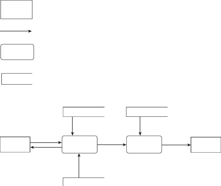
As illustrated in Figure 6.8, a data flow diagram is composed of four elements: (1)
source or destination of data, (2) flow of data, (3) processing, and (4) data store. A high-
level example of using a data flow diagram to depict a customer order system is shown
in Figure 6.9. In this example, both the source and the destination of the data is the cus-
tomer. The shipping clerk only receives data. Orders are processed by order processing,
Figure 6.8 A data flow diagram.
Source or destination of data
Flow of data
Processing
Data store
Figure 6.9 An example of a data flow diagram depicting a customer order system.
Inventory information Package data
Product availability
information
Customer credit,
address, etc.
Packaging
details
Orders
Invoice
Customer information database
Order processing
Customer
Packaging
Shipping
instructions
Shipping
clerk
Shipping
labels
6.4 Requirements Definition, Prototyping, and Reviews
121
91998_CH06_Tsui.indd 121 1/10/13 6:31:25 AM

and shipping instructions are sent to packaging. There are three data stores, which may
be currently in paper file form and later converted to databases during the design phase.
The data flows are represented with arrows and accompanied by a description of the
information that is flowing.
Although the ER diagram is not used to show the flow of information, it is used to
depict the relationship among entities. It is also used to show the attributes of the entity.
Again, as is the case with a DFD, it is initially used during the requirements analysis phase
and kept on through the design phase. An example is shown in Figure 6.10, which illus-
trates the relationship between the objects or entities of author and book. The relation-
ship is that the authors write books. That relationship is shown with a line connecting the
two objects and with the word writes shown above the line. The relationship may have
two constraints:
n
Cardinality
n
Modality
The cardinality specifies the number of participants. Note that in the requirement
shown in this figure an author may write several books, but a book may not have
multiple authors. Thus it is somewhat restrictive. An advantage of using well-defined
language, such as the ER diagram, is that it is more precise. The restrictive relationship
between the authors and the books, as stated in Figure 6.10, should trigger someone
to ask if it is in fact correct at a requirements specification review time. The crow’s foot
represents multiple occurrences. There may be several forms of cardinality:
n
One-to-one
n
One-to-many
n
Many-to-many
An example of a one-to-one relationship may be a diagram that shows people sitting
on chairs. Each person sits on only one chair, and each chair may be occupied by only
one person. The one-to-many example is already shown in Figure 6.10. A many-to-many
relationship can be shown by changing the Figure 6.10 example so that it shows a rela-
tionship where an author may write several books and a book may be written by several
coauthors.
Figure 6.10 An entity-relationship diagram.
Author Book
writes
1 m
Cardinality: Specifies the number of occurrences of entities
Modality: Specifies the necessities of relationship to exist
Author Book
122 Chapter 6 Requirements Engineering
91998_CH06_Tsui.indd 122 1/10/13 6:31:25 AM

The modality of the relationship specifies whether the existence of an entity depends
on its being related to another entity via this relationship. In Figure 6.10, a circle shows
that book is optional because there are authors who have not completed any book.
However, the vertical bar indicates that author is mandatory in that there is no book
without an author. Thus the requirement shown in Figure 6.10 states that books are
optional and authors are mandatory in this relationship.
Each of the entities shown in the relationship may have several attributes. During the
requirements phase, these attributes are also defined and analyzed. A pictorial example
of an entity and its attributes is shown in Figure 6.11. The entity, employee, and its attri-
butes are shown in both graphical and tabular forms. The tabular form may add further
columns to record, as part of the requirements. As the project moves along into the
design phase, the tabular form may be converted into a data dictionary.
Using various modeling languages such as UML, DFD, or ERD to define the require-
ments is a form of prototyping. In this case, we are prototyping the functional flow, the
data flow, or the data attributes. As part of the requirements gathering and analysis, the
user interface is a vital component that cannot be forgotten. Here we are not interested
in the system internals and the algorithms. Instead, we focus on the users and their
interaction with the system. We focus on the main use cases and their interfaces with the
users. Two main aspects of user interface must be analyzed during requirements time:
n
Visual looks and display
n
Interaction with people and flow
In the early days, the user interfaces were modeled with paper boards and flip
charts and were known as low-fidelity prototyping. Today, the user interface is pro-
totyped with machine-executable code during requirements gathering and analysis
time. These prototypes are sometimes kept and turned into the final release code. One
of the earliest tools used for rapid prototyping of the user interface was HyperCard,
which runs on Apple computers. Today, one of the most popular tools for quick user
Figure 6.11 Example of an entity and its attributes.
Employee
Address
Street City State Zip
Name Age
Employee
–Name
–Age
–Address
–Street
–City
–State
–Zip
(a) Graphical (b) Tabular
6.4 Requirements Definition, Prototyping, and Reviews
123
91998_CH06_Tsui.indd 123 1/10/13 6:31:25 AM

interface prototyping is Microsoft’s Visual Basic. Also, with the growing popularity of
Agile methods, the user-interface requirements are often prototyped with heavy user
participation (see Ambler 2004). In addition to visual interfaces, there is a small but
growing demand today for audio and video interfaces. For an introduction to Internet
video, see Stolarz (2005) and for more details on developing and prototyping good
user interfaces see Hix and Hartson (1993) and Shneiderman and Plaisant (2005).
Closely related to requirements analysis and user-interface prototyping is the review
of requirements with the users and customers. These reviews may be conducted
informally and very frequently as proposed by the Agile methods or they can be more
formal in nature. Formal reviews and inspections methodology was first introduced by
Michael Fagan of IBM in the early 1970s. Although the target of all those early formal
inspections was to reduce design and programming errors, the same inspection process
may be used for reviewing requirements in reducing errors and misunderstandings of
requirements as early as possible. Most of the practitioners choose a hybrid between
the formal inspections and informal reviews. Whichever review technique you choose,
it is important to realize that reviewing requirements with users and customers is an
essential part of the requirements analysis and prototyping. Catching requirements
errors early is of extreme significance in that a single requirement error often expands
into multiple design errors, each of which in turn may become a source of several
programming errors. Preventing a requirement error from escaping is definitely an
economically worthwhile activity.
After reviews are conducted, any modification and correction must be made to the
requirements definitions. Sometimes a follow-up review over the modifications and
changes is necessary if the extent of corrections is very large. Although it is better not
to become overly bureaucratic, these changes must be documented clearly so that a
requirement error, as mentioned earlier, does not escape through downstream activities
such as design, coding, and testing and end up in the customer release.
6.5 Requirements Specification and Requirements Agreement
Once the requirements have been analyzed and reviewed, it is prudent to put them into
a requirements specification document. The amount and extent of detail that must be
included in this depends on several parameters:
n
Size and complexity of the project
n
Subsequent multiple follow-on releases that have been planned
n
Estimated and expected number of customer support activities
n
Knowledge and experience of the developers in the subject area
The more complex and large the number of requirements, the more there is a need to
specify the requirements formally and completely. The more follow-on releases that are
planned, the more clearly and orderly the requirements specifications must be to allow for
such future activities. If the estimated number of customers is large, perhaps in the millions,
then the requirements specification must be detailed and complete so that maintenance
and support activities can be performed in an orderly fashion. If the testers, designers,
and code developers have very little subject matter knowledge or experience in the
124 Chapter 6 Requirements Engineering
91998_CH06_Tsui.indd 124 1/10/13 6:31:25 AM

application domain area for which the software is being developed, then it is imperative
to have a detailed requirements specification document.
IEEE has a recommended standard, guideline 830, for the Software Requirements
Specification document that complies with the IEEE/EIA Standard 12207.1-1997.
Essentially, the guideline specifies that the following material should be included in a
software requirements specification (SRS):
n
Introduction: Provides an overview by describing the purpose, scope, references, and
definitions of terms.
n
High-level description: Provides a general description of the software product, its major
functions, user characteristics, major constraints, and dependencies.
n
Detailed requirements: The following is provided here: (1) detailed description of each
functional requirement by input, process, and output; (2) descriptions of interfaces
that include user interfaces, system interfaces, network interfaces, and hardware
interfaces; (3) a detailed description of performance requirements; (4) a list of design
constraints such as standards or hardware limitations; (5) additional descriptions
of attributes such as security, availability, and recoverability; and (6) any additional
unique requirements.
A copy of this IEEE guideline may be purchased at the IEEE website listed in the
Suggested Readings section.
As the last step of requirements engineering, the requirements specifications docu-
ment should be “signed off.” This may be in a form of a formal document such as a
contract, or an informal communication such as an email. Regardless of the final form of
sign off, this activity closes the requirements phase and provides a formal baseline for the
requirements specifications. Any future changes should be controlled or at least closely
monitored to prevent uncontrolled growth and changes of requirements in the future.
Uncontrolled requirements changes represent a major problem and are a critical cause
for many software project failures, as discussed in Chapter 3.
6.6 Summary
This chapter covered the following major steps of requirements engineering:
n
Elicitation
n
Documentation and definition
n
Specification
n
Prototyping
n
Analysis
n
Review and validation
n
Agreement and acceptance
For requirements elicitation, both high-level and detailed information gathering were
discussed. More specifically, the following detailed information categories were identi-
fied as part of the elicitation process:
n
Individual functionality
n
Business flow
6.6 Summary
125
91998_CH06_Tsui.indd 125 1/10/13 6:31:25 AM

n
Data, formats, and information needs
n
User interfaces
n
Interfaces with other systems
n
Constraints such as performance, reliability, and security
The gathered requirements need to be analyzed through categorization and group-
ing. Several methodologies, including prioritization techniques, are introduced for
grouping the requirements. Also, requirements need to be traceable.
Although English is still the predominant language for documenting the require-
ments, there are several modeling languages that are used today. These include UML,
DFD, and ERD. As part of the requirements analysis cycle, requirements are also proto-
typed using these modeling languages. Executable prototypes are more popular today,
especially with user interfaces. The user and quality reviews of these prototypes and
categorized requirements are essential in preventing errors from escaping into later soft-
ware engineering activities and into the customer release. Thus as many of the require-
ments as possible should be reviewed.
Finally, a software requirements specification document should be produced and
signed off by the customer as a baseline for any future modification.
6.7 Review Questions
1. List and describe at a high level the steps involved in software requirements engi-
neering process.
2. What are the three main items that must be planned prior to conducting require-
ments engineering?
3. What are the six main dimensions of requirements that you need to address when
collecting requirements?
4. List four items that are included in the description of high-level business profile.
5. List and describe three items that you will need to consider when prioritizing
requirements.
6. What is the viewpoint-oriented requirements definition method used for?
7. Consider the situation where you have the following four requirements for an
employee information system:
n
Response time for short queries must be less then 1 second.
n
In defining employee record, user must be able to enter employee name and
be prompted for all the remaining employee attributes that are needed for the
employee record.
n
Employee information may be searched using either the employee number or
employee’s last name.
n
Only an authorized search (by the employee, by managers in his or her chain
of command, or human resource department personnel) will show employee
salary, benefits, and family information.
126 Chapter 6 Requirements Engineering
91998_CH06_Tsui.indd 126 1/10/13 6:31:25 AM

Perform an analytical hierarchy process and rank these based on your choices.
8. Explain in an ER diagram the relationship between programmers and modules
where a programmer may write several modules and each module may also be
written by several programmers.
9. What are the four types of requirements traceability?
6.8 Exercises
1. Discuss why it is important to document the requirements specified; list three
reasons.
2. Based on your answer to Exercise 1, discuss how a novice Agile software devel-
oper involved in collecting and documenting requirements may misapply the
Agile methodology.
3. During analysis of requirements, we often have to categorize and then prioritize
items. Discuss why we would need to do these activities.
4. In collecting requirements for an employee information system, the employee
is a major entity. What are some of the attributes of this entity that you would
consider asking as part of the requirements? Express the entity and attribute in an
entity-attribute table. Add an additional column to the table and express the data
characteristics for each of the attributes.
5. Using one of the books on UML presented in the Suggested Readings section as
a reference, discuss the similarity between use case in UML and business flow in
the six dimensions of requirements.
6. What purpose does the final signing off of the requirements specifications docu-
ment serve? What are the potential problems that may arise if there is no such
process?
6.9 Suggested Readings
S. W. Ambler, The Object Primer: Agile Model Driven Development with UML2, 3rd ed. (New
York: Cambridge University Press, 2004).
P. Chen, “The Entity-Relationship Model—Towards a Unified View of Data,” ACM Trans-
actions on Database Systems 1 (March 1976): 9–36.
T. DeMarco, System Analysis and System Specification (New York: Yourdan Press, 1978).
M. Fagan, “Design and Code Inspections to Reduce Errors in Program Development,” IBM
Systems Journal 15, no. 3 (1976): 182–211.
M. Fowler, UML Distilled: A Brief Guide to the Standard Object Modeling Language, 3rd ed.
(Reading, MA: Addison-Wesley, 2003).
C. Gane and T. Sarsen, Structured Systems Analysis: Tools and Techniques (Upper Saddle
River, NJ: Prentice Hall, 1979).
6.9 Suggested Readings
127
91998_CH06_Tsui.indd 127 1/10/13 6:31:26 AM

D. Hix and H. R. Hartson, Developing User Interfaces: Ensuring Usability Through Product and
Process (New York: Wiley, 1993).
IEEE Computer Society, Software Requirements Specifications guideline, which com-
plies with IEEE Recommended Practice for Software Requirements Specification, http://
ieeexplore.ieee.org/ie14/5841/15571/00720574.pdf, accessed September 2012.
J. Karlsson and K. Ryan, “A Cost-Value Approach to Prioritizing Requirements,” IEEE Soft-
ware (September/October, 1997): 67–74.
G. Kotonya and I. Sommerville, “Requirements Engineering with Viewpoints,” BCS/IEE
Software Engineering Journal 11, no. 1 (January 1996): 5–18.
——Requirements Engineering: Processes and Techniques (New York: Wiley, 1998).
D. Leffingwell and D. Widrig, Managing Software Requirements: A Unified Approach (Read-
ing, MA: Addison-Wesley, 2000).
M. Mannion et al., “Using Viewpoints to Determine Domain Requirements,” In E. J. Braude,
Software Engineering Selected Readings (Los Alamitos, CA: IEEE, 2000): 149–156.
Object Management Group, Unified Modeling Language, http://www. omg.org.
K. Orr, “Agile Requirements: Opportunity or Oxymoron?” IEEE Software 21, no. 3 (May/
June 2004): 71–73.
B. Ramesh and M. Jake, “Towards Reference Model for Requirements Traceabiltiy,” IEEE
Transactions on Software Engineering (January 2002): 58–93.
K. Ryan and J. Karlsson, “Prioritizing Software Requirements in an Industrial Setting,”
Proceedings of the 19th International Conference on Software Engineering (1997): 564–565.
G. Schneider and J. P. Winters, Applying Use Cases: A Practical Guide (Reading, MA: Addi-
son-Wesley, 1998).
B. Shneiderman and C. Plaisant, Designing the User Interface: Strategies for Effective Human-
Computer Interaction, 4th ed. (Reading, MA: Addison-Wesley, 2005).
I. Sommerville, Software Engineering, 7th ed. (Reading, MA: Addison- Wesley, 2004).
I. Sommerville and P. Sawyer, Requirements Engineering: A Good Practice Guide (New York:
Wiley, 1997).
D. Stolarz, Mastering Internet Video: A Guide to Streaming and On-Demand Video (Reading,
MA: Addison-Wesley, 2005).
F. Tsui, Managing Software Projects (Sudbury, MA: Jones and Bartlett, 2004).
K. E. Wiegers, Software Requirements, 2nd ed. (Redmond, WA: Microsoft Press, 2003).
128 Chapter 6 Requirements Engineering
91998_CH06_Tsui.indd 128 1/10/13 6:31:26 AM
..................Content has been hidden....................
You can't read the all page of ebook, please click here login for view all page.