
This appendix documents the Matrix class as used in the project in Chapter 3. This class can be used to drive an LED matrix, as shown in Chapter 3, for example:
When working with the MAX7219 to display a bar graph in an LED matrix
To control a CPU meter using PWM
To display a Pi symbol on the matrix
This class is very simple compared with that for GPIO and MAX7219. What you will notice immediately in the sections that follow is that the Matrix class inherits from the MAX7219 class. By doing so, it supports all the methods provided by the MAX7219 but adds a few more related to the Matrix operation.
With the default build and install PREFIX=/usr/local, your installed librpi2 header files should be located in /usr/local/include. In your program use:
#include <librpi2/matrix.hpp>
If necessary, add the compiler option -I/usr/local/include.
With the default build and default install PREFIX=/usr/local, your installed librpi2 library should be located here:
/usr/local/lib/librpi2.a
When linking your program, add the options -L/usr/local/lib -lrpi2 to the link step of your make file.
The public portion of the Matrix class is shown below (note how this class inherits from MAX7219, which is documented in Appendix D):
class Matrix : public MAX7219 {
    ...snipped for clarity...
public:

    Matrix(int clk,int din,int load);
    ~Matrix();

    void set_meter(int gpio_pin);   // Configure 1 mA Meter
    void set_deflection(double pct);// Set meter deflection

    int display(int row,int v07);   // Display a bar
    int Pi();                       // Draw Pi
};
Like the MAX7219 constructor, this constructor requires arguments:
Matrix(int clk,int din,int load);
Three arguments determine how the Matrix is wired to the Raspberry Pi GPIO pins:
clk: This is the GPIO output connected to the MAX7219 CLK input (clock)
din: This is the GPIO output connected to the MAX7219 DIN input (data input)
load: This is the GPIO output connected to the MAX7219 LOAD input (load strobe)
The Matrix constructor calls upon the MAX7219 constructor to initialize the device (see Appendix D for the device initialization steps that are performed).
Like the MAX7219 class, part of the Matrix constructor initialization includes the GPIO class as well. However, a constructor does not return any error indication if the GPIO access fails (GPIO access requires root access and a common cause for failure). For this reason, you should instantiate the GPIO class ahead of the Matrix and test for its success (see Appendix A). Once one instance of GPIO succeeds, the others are guaranteed to succeed because they share common resources.
An example instantiation of GPIO and the test is given below:
GPIO gpio;

if ( gpio.get_error() != 0 ) {  // Test that GPIO opened ok
    fprintf(stderr,"%s: GPIO
",strerror(errno);
    exit(1);
}

Matrix matrix(16,26,21);      // Instantiate matrix class
To display a bar graph row on the Matrix display, use the display() method:
int display(int row,int v07);
The function returns zero upon success or a system error code upon failure.
The row argument selects the matrix row (0 through 7), while argument v07 selects the bar graph height (0 though 8). A value of zero displays a blank row, while values of 1 through 8 show the corresponding number of LED pixels in a bar graph. The following example illustrates how to display a bar graph in row 3 with a height of 4 LED pixels:
Matrix matrix(16,26,21);
int rc;

rc = matrix.display(3,4);  // row 3 bar graph is 4 pixels high
assert(!rc);
When the mtop command exits, it leaves the Matrix display showing a π (Pi) symbol. It does so by invoking the Pi() method:
int Pi();
The method returns zero when successful or a system error code when it fails. An example is shown below:
Matrix matrix(16,26,21);
int rc;

rc = matrix.Pi();
assert(!rc);
Figure E-1 shows how the Pi is formed on the display:
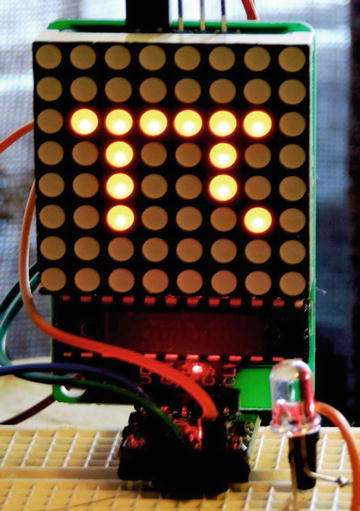
Figure E-1. Pi shown on the LED matrix
If you want a meter to move in tandem with total usage, you can configure the GPIO pin for it using the set_meter() method:
void set_meter(int gpio_pin);
Using this method, you can configure which GPIO pin should be used for PWM modulated output. It must, however, be one of the PWM pins:
GPIO 12 or 18 for PWM0
GPIO 13 or 19 for PWM1
No error code is returned.
The set_deflection() method takes a floating point value in percentage (0 through 100.0) and adjusts the PWMx peripheral to provide a meter deflection. See Chapter 3 for more information.
void set_deflection(double pct);
The following method call puts the meter deflection at 75%:
Matrix matrix(16,26,21);
int rc;

matrix.set_deflection(75.0);