
Designers had been asking for 3D manipulation tools in Flash for a long time. In fact, this feature has been requested in some form or another since the beginning of the product line. That makes sense if you consider that the mid-1990s promise of Virtual Reality Modeling Language (VRML) gave web surfers a taste of 3D before Flash ever hit the market. VRML was a great idea, but it was ahead of its time and, sadly, didn't go very far. In any case, it was more of a programmer's pursuit than something a designer would want to grapple with.
Then came Flash, which sparked an explosion of stylish 2D designs that began to reshape what the web experience meant. Over the years, intrepid designers began experimenting with ways to simulate three dimensions in their SWFs. They used centuries-old techniques to accomplish these goals—for example, increasing the size of an object to "move it forward"—which were the same practices used in real-life painting and sketching. Nothing in the Flash interface provided direct assistance. This all changed in Flash CS4. The requested tools arrived, and they're here to stay in CS5. If you'll pardon the pun, they open a whole new dimension in creative potential.
Here's what we'll cover in this chapter:
Understanding the 3D environment
Using the 3D tools
Positioning symbols in 3D space
The following files are used in this chapter (located in Chapter09/ExerciseFiles_Ch09/Exercise/):
The source files are available online at www.friendsofED.com/download.html?isbn=1430229940.
What you'll learn in this chapter pertains to the 3D-related tools in the Flash CS5 Tools panel, along with some workflow suggestions to help you get the most out of them. This will be enough to introduce you to a new playground.
If you want to supplement the benefits of the new 3D tools with older techniques, consider checking out Flash 3D Cheats Most Wanted by Aral Balkan, Josh Dura, et al. (friends of ED, 2003). To learn about simulating 3D with ActionScript 3.0, see Chapters 15 through 17 of Foundation ActionScript 3.0 Animation: Making Things Move! by Keith Peters (friends of ED, 2007). For the perfect introduction to using a 3D engine (Away3D) to create "real" 3D in Flash, see The Essential Guide to 3D in Flash by Richard Olsson and Rob Bateman (friends of ED, 2010).
When it comes to 3D in Flash, consider this feature as you would pizza. No matter what the server brings from the kitchen, you're going to love it. Capisce? Good. Now that you're thinking of a delicious pie with all your favorite toppings, tease your mind back to Flash for a moment. Between bites, wrap your brain around three levels of wow factor:
Good ("Hey, this is super cool!")
Better ("My jaw just hit the floor!")
Best ("Somebody bring me oxygen!")
Game consoles like the Wii, PlayStation 3, and Xbox 360 have redefined what consumers expect in terms of 3D interactivity. This is the bring-me-oxygen stuff—the Best level—which isn't available in Flash. We need to mention that right out of the gate. (Hey, are you going to eat that pepperoni?)
On the design side of things, you would need specialized 3D modeling software to produce that sort of content for game consoles, television, or film. We're talking about software like Maya, 3Ds Max, Blender, or Cinema 4D. These industrial-strength powerhouses are designed specifically for the task and are capable of turning out extremely complex, high-resolution output. Examples include everything from Hollywood aliens, dragons, and virtual stunts, all the way to vehicle mock-ups, such as the Hot Rod created by Belgian CG artist Laurens Corijn for cg.activtutsplus.com, shown in Figure 9-1.
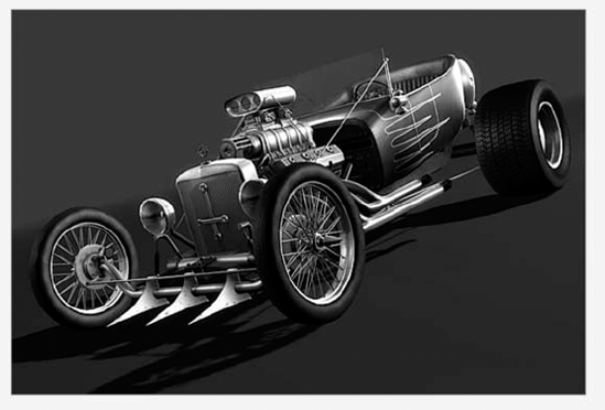
Figure 9-1. Highly complex 3D models are created in software designed for the task, which doesn't include Flash (car modeled by Laurens Corijn).
For better or worse, advanced 3D modeling is not the sort of field trip you'll be taking in Flash CS5—at least, not with the new drawing tools. Don't let that get you down, though. For you code jockeys, be aware that ActionScript does give you a surprising range of possibilities, but you'll probably want to use third-party code libraries to pull it off.
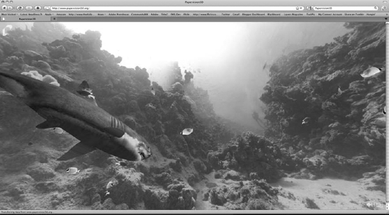
For the jaw-dropping stuff—the Better level—you'll want to check out Papervision3D (www.Papervision3D.org/). This is open source software (created by core team members Carlos Ulloa, Ralph Hauwert, John Grden, Tim Knip, and Andy Zupko) consisting of a framework of ActionScript 3.0 and 2.0 class files. Papervision3D allows programmers to create a range of 3D primitives (basic shapes, from which other shapes can be built), and even import COLLADA (an open XML standard) data files from external modeling applications, and then bring those models to life in complex ways, as shown in Figure 9-2. Yup, that's Flash, and every fish, including the shark, is interactive. In addition, the entire scene gives you a complete 360-degree view of the reef when you drag the mouse. Interactive. In many ways, this is comparable to VRML.
If you're experienced with previous versions of Flash, you may have heard of Swift 3D (www.erain.com). Swift 3D is a best-of-breed, low-cost modeler closely integrated with Flash in that it exports models as SWFs. These SWFs can then be loaded or imported into your normal work files and used to simulate three-dimensional objects. The latest version of Swift 3D even exports to Papervision3D, so you're in good hands with this product. Designers typically import Swift 3D assets as elements of otherwise two-dimensional layouts. That workflow is every bit as useful in Flash CS4 as it has been in the past, but it's not the topic we're covering here.
What you'll learn about in this chapter is the super-cool stuff—the Good level—and a great place to start if you're new to nonscripted 3D in Flash (which pretty much means anyone using Flash CS5 for the first time). We won't be covering 3D in terms of ActionScript. It's simply a topic that merits its own book (such as The Essential Guide to 3D in Flash, mentioned earlier), and we again direct your attention to www.Papervision3D.org or www.away3d.com. What you are about to discover, behind that heavenly melted mozzarella, is a pair of shiny tools that first appeared in Flash CS4 that give you direct three-dimensional manipulation of your symbols. But first, we need to cover a bit of theory.
When you open your eyelids and cast your gaze ahead, even if all you can see are the tweed walls of your cubicle, you have a horizon in front of you. Turn your head, and it's still there. The horizon might be hidden, but the principles of perspective still apply, just as gravity still applies even when you climb a tree or take a dive in the swimming hole. In a theoretical sense, this horizon holds something called a vanishing point, which is a special location, usually off in the distance, where the parallel lines in your view seem to converge. It's a natural optical illusion, and you see it every time you stare down a length of railroad tracks. In linear perspective drawings, you can have as many as three vanishing points, but Flash keeps things manageable for you by providing one. Here's how it works.
Imagine you are in a huge square in front of a museum. The square is paved with square paving stones, and you take a picture from where you are in the square to the front door of the museum. If you drawn lines along the surface of the square that follow the parallel lines in the pattern of the paving stone, those lines will eventually intersect at a place, as shown in Figure 9-3, called the vanishing point.
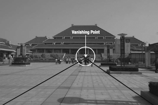
Figure 9-3. The vanishing point is the location where parallel lines appear to converge on the horizon.
That vanishing point is your key to understanding how the 3D Rotation and 3D Translation tools, coupled with the Transform panel and Properties panel, give you access to 3D manipulation in Flash. Without this concept, you can still experiment with these tools and have plenty of fun. But if you want to actually wallpaper a three-dimensional cube with movie clips or project a photo on to a wall that isn't displayed head-on, you should keep a firm grip on the notion of those perspective lines. By actually drawing them as temporary guides over your artwork, you'll find the new 3D tools a ton easier to work with.
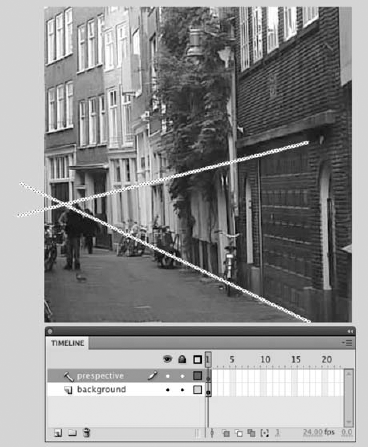
Consider the real-world example of the Amsterdam street scene shown in Figure 9-4. You're going to use this photo to get acquainted with the new tools, so let's put those perspective lines in place. Here's how:
Open the
Amsterdam.flafile from theExercisefolder for this chapter. Note the already-imported photo in a layer namedbackground.Create a new layer, and name it
perspective. Right-click (Windows) or Control+click (Mac) the new layer's name, and selectGuidefrom the context menu. This converts the layer into a guide layer, which means you can see its contents during authoring, but anything on this layer will disappear in the published SWF, which is exactly what you want.Select the
Linetool, and make sure theObject Drawingbutton is not selected in theToolspanel. Use theLinetool to draw some lines, like those in Figure 9-4, into theperspectivelayer. Start from the lower-right corner, and follow the edge where the garage door meets the street.Repeat this process with another line that follows the top of the garage door, until you can pin down the vanishing point to the far left.
Save your file, because you're going to revisit it later in the chapter. You can compare your work with the completed
Amsterdam.flain theCompletefolder, which shows the two lines already in place.
As we've mentioned, Flash CS5 provides two 3D tools: the 3D Rotation tool and the 3D Transformation tool.
In terms of visual cool factor, the 3D Rotation tool falls into the realm of "wicked cool." This tool allows you to quickly and intuitively rotate a movie clip in 3D space. In previous versions of Flash, this was possible only with shapes, and even that technique required a bit of careful nudging with the Free Transform tool. You simply couldn't do this with a symbol. Now you can, and that means you can perform perspective transforms on complex artwork, imported photos, and, yes, even video. Kind of makes the corners of the mouth go up, doesn't it?
To illustrate how groundbreaking this is, let's start with how it used to be.
Prior to this release of Flash, 3D perspective was not exactly up there in the realm of "really easy to accomplish." You needed to actually draw in perspective by hand or use the Free Transform tool to simulate 3D rotation. Let's go "old school" and see how that technique works:
Create a new FLA file, and select the
Rectangletool. Make sure theObject Drawingbutton is not selected so that your shape is nothing more than a fill, with an optional stroke. Color settings don't matter. Draw a square approximately 300 × 300 pixels.Once you've drawn your shape, double-click to select it, and then change to the
Free Transformtool. You'll see a number of buttons appear in the options area of theToolspanel.Click the
Distortbutton—it looks like a paper airplane at the bottom of theToolspanel, which lets you make perspective distortions by individually clicking and dragging each corner of your square. Go ahead and do precisely that. With a bit of practice, you can reshape the square to appear as if you're standing above it, looking slightly down on it, as shown in Figure 9-5.Click away from the reshaped square to deselect it. Now double-click the shape to select it again. When you do—assuming that
Free Transformis still your current tool—you'll notice that the shape's bounding box no longer follows the contours of the shape. That's to be expected, since the bounding box represents the full area required to contain the shape.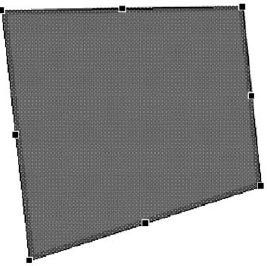
Figure 9-5. The
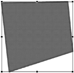
Distortoption of theFree Transformtool lets you simulate perspective with shapes.At this point, if you want to adjust your perspective distortion (see Figure 9-6), you'll find it much harder to accomplish with precision, simply because the bounding box no longer matches the corners or edges of the shape. Worse, you can't do a thing with imported photos, if that's your aim. Let's see the problem with photos.
Import the
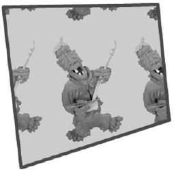
FigurineSmall.jpgincluded in theExercisefolder for this chapter to yourLibrary, and set it as the bitmap fill for the reshaped square. Notice that the bitmap simply tiles inside the shape and doesn't "play along" with this distortion game in the least (see Figure 9-7). After all, this is a simulation of perspective, not the real thing.
Note
If bitmap fills have you scratching your head, flip back to Chapter 2 for a quick refresher.
If you want to turn your world around—practically speaking, and in a good way—you'll need to step over to the 3D Rotation tool. This is where it gets really neat, folks.
Start a new Flash document, and import the
Figurine.jpgimage from yourExercisefolder to the stage.Select the photo, and convert it to a movie clip symbol.
Step 2—converting to a movie clip—is the deal maker. Without it, the 3D drawing tools are useless. They work with movie clips, period. Keep that in mind, whatever artwork you intend to spin around in 3D space. Fortunately for you, movie clips are a supremely useful symbol.
Select the
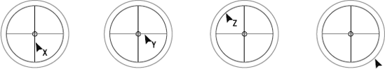
3D Rotationtool, and click the movie clip. You'll see a somewhat complex looking bull's-eye.Figure 9-8 shows the same bull's-eye repeated four times, with the mouse pointer moving from area to area. Notice how the mouse pointer changes. Each of those lines and circles has a meaning. Hover near the vertical red line (far left in the figure), and the mouse pointer turns into a black arrow with an
Xnext to it. This line controls the x-axis rotation, which you'll see in just a moment. Hover near the horizontal green line—the second bull's-eye in Figure 9-8—and you'll see the letterY, which controls y-axis rotation. Hover near the inner large blue circle, and you'll see aZ, which controls the z-axis. The outer orange circle (far right in the figure) isn't associated with a letter, because it affects all three axes at once. The tiny circle in the middle represents the 3D rotation center point, and it's basically the pivot for this sort of rotation.To see what an x-axis rotation does, hover near the vertical red line, and then click and drag sideways, slowly back and forth. You'll see a pie chart-like wedge appear inside the bull's-eye (see Figure 9-9), which gives you an idea of the current size of the angle. In the figure, the angle is approximately 45 degrees.
To adjust y-axis rotation, hover near the horizontal green line, and then click and drag slowly up and down. For z-axis and all-axis rotation, click and drag in any direction you please.

The visual effect on the movie clip is easy to see. As shown in Figure 9-10, the rotations work as follows:
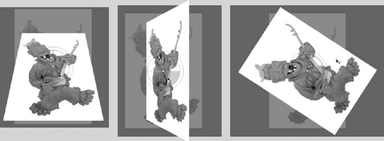
Experiment with rotation, keeping an eye on the
Transformpanel (Window
Still in the
Transformpanel, scrub each of the hot text values in the3D Rotationarea. They provide an alternate way to rotate along the x, y, and z axes—with the added benefit that you can enter exact values by hand.Feel free to save your file.
Now that you understand rotation, it's time to learn how to position your object in Flash's 3D space. This sort of movement is called translation, and it features a tool all its own.
Because Flash is primarily a two-dimensional interface, the 3D Translation tool may not immediately make sense. Without the context of a vanishing point, it may seem like nothing more than another version of the Selection tool. It lets you move things, but the way it works is more restrictive than the Selection tool, which, by contrast, lets you simply click and drag. So what gives? To answer that question, let's take another visit to that street in Amsterdam. The plan is to project the figurine image on to that garage door.
Open the
Amsterdam01.flafile you saved earlier in the chapter. When it opens, you will see the vanishing point guides created earlier and the figurine image, which is a movie clip, sitting in the photo layer.Select the figurine. Use the
Free Transformtool or theTransformpanel to resize the photo to about 65 percent of its actual size (approximately 100 × 100 pixels). Try to have the top and bottom corners on the right edge of the photo somewhat align with the guides. An easy way of doing this is to move the transform point to the bottom-right corner of the movie clips.Note
According to recommended best practices, you would normally import a photo that doesn't require such a change in scale, because even though it looks small in the SWF, the actual imported file is big, which adds to the SWF's file size. In this exercise, you're giving yourself leeway as you experiment.
At this point, it's time to make use of the perspective lines in the guide layer. Using the
Selectiontool, click the figurine movie clip to select it. Twirl down the3D Position and Viewarea of theProperties panel, and note theVanishing pointvalues at the bottom of that area, next to aResetbutton, as shown in Figure 9-12.Until you adjust it otherwise, the vanishing point is centered on the stage. Click and scrub the
Xvalue slowly to see a set of crosshairs appear over the photo.The crosshairs represent the official vanishing point Flash uses to position 3D objects. When your goal involves matching up assets to actual background images, you'll find that helps to match Flash's vanishing point with the real-world vanishing point in your reference artwork. Let's do it.
Scrub the
Xvalue far to the left so that the horizontal portion of the crosshairs lines up with the point where the perspective lines intersect. When you're satisfied, do the same with theYvalue to lift it a bit higherClick the figurine to select it, and switch to the
3D Translationtool. You'll see a pair of arrows arranged in an L shape on the image.Figure 9-13 shows the same set of arrows repeated four times, with the mouse pointer moving from area to area, changing as it does. The arrows and the heavy dot each have their own meaning. Hover near the horizontal red line (far left in the figure), and the mouse pointer turns into a black arrow with an
Xnext to it. This arrow controls the x-axis position. Hover near the vertical green line, and you'll see the letterY, which controls the y-axis position. You'll use this in just a moment.The heavy dot takes a bit more dexterity. Hover in the center of the dot, and you'll see a
Z, which controls movement along the z-axis. Hover near the edge of the dot, and you won't see any letters. Why? Dragging at this point lets you reposition the 3D center point for this object, which affects how translation is applied (the center point's position isn't nearly as obvious with translation as it is with rotation).Hover near the green y-axis arrow, and then click and drag down until the photo appears to rest on the perspective line that runs along where the door meets the street.
Use the
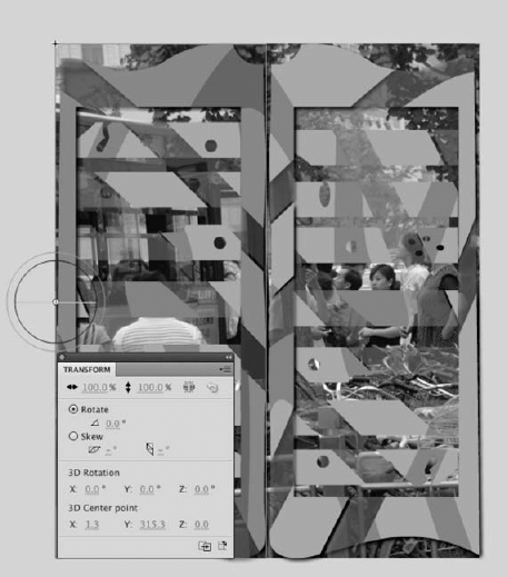
Transformpanel to scrub theYvalue in the3D Rotationarea until the bottom edge of the photo roughly follows the line of the pavement as it meets the buildings (see Figure 9-14). You can alternatively use the3D Rotationtool to accomplish the same task, but theTransformpanel gives you a bit better control. If you're surprised at how much the image gets stretched, don't worry. We'll show you how to fix that later in the chapter. The stretch is because of the "distance" of the vanishing point, off to the side. What you need to pay attention to is how the top and bottom edges of the image roughly follow the vanishing point guides.With the
Transformpanel open, scrub across theResizevalues at the top to shrink the image. Be sure that the link icon is selected to ensure uniform scaling. As you scale the image, notice how theXandYvalues shown in Figure 9-15 aren't the same. This is because of the 3D translation applied to the image that aligns it to the perspective.Use the
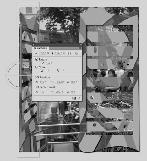
Y Translationarm to move the image so that its bottom edge sits on the bottom vanishing point guide.With the image somewhat in place and resized, you are now going to put it into its final position. What you won't be doing here is changing over to the
Selectiontool and pulling and pushing the image into place. You will need to use the3D Translationtool, theTransformpanel, and thePropertiespanel to "slide" the image into position on the x-axis and to "push" it into the door on the z-axis.To understand X and Z movement—at least in the current scenario—think of those perspective lines in terms of the ones shown in Figure 9-3 in the square in front of the museum. In that earlier figure, the line seems to be growing out of the image toward you, because its vanishing point is at the "back" of the square. In that case, or when the vanishing point is centered on the stage, Z movement causes the object to get bigger or smaller as it moves "out" or "in." The apparent scaling is a perspective effect that happens because the z-axis is pointing at you. In this case, the z-axis is pointing somewhere over your right shoulder. It's as if you're looking at the figurine image from the side. Why? Because the vanishing point is over to the left.
Let's illustrate this.
Hover over the heavy dot until you see the letter
Zappear in the mouse pointer. Slowly drag up and down. The image still changes scale, but more important, it moves sideways, zooming along the pavement. That's because the "front" of the z-axis is pointing toward the right, and the back is pointing toward the vanishing point at left.Now hover over the horizontal red line until you see the mouse pointer acquire an X. Click and drag slowly left and right. At first, the movement might look similar to Z movement, but there's an important difference. Yes, there is some left-and-right movement, but because of the position of the vanishing point, the photo seems to be moving "onto the street" or "into the door," as depicted in Figure 9-16.
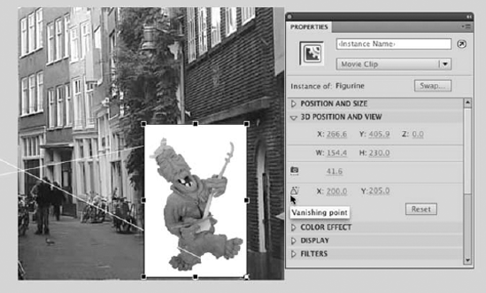
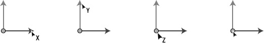
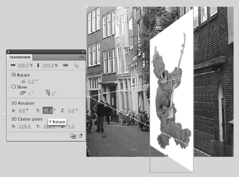
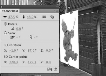
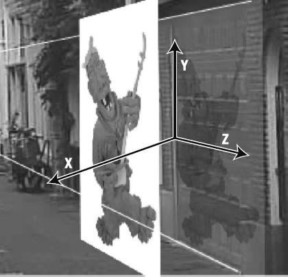
Figure 9-16. The orientation of the x-, y-, and z-axes depends on the position of the vanishing point.
As you are most likely discovering, using the arrows on the 3D Translation tool to move a selection can be a bit tricky. Here's a more precise method:
Select the image on the stage and open the
Propertiespanel.Twirl down the
3D Position and Viewoptions.Switch to the
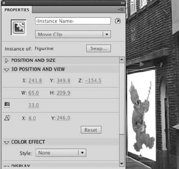
3D Translationtool, and scrub across one of the handles. Pay attention to how the values in the X, Y, and Z areas, as shown in Figure 9-17, in thePropertiespanel change as you drag the arrow. Now scrub across the values in thePropertiespanel. The selection moves on the axis you are scrubbing.What does that little camera in the
3D Position and Viewproperties do? Scrub across the value. That little gem is thePerspective Angle, and as, you have seen, it moves the selection along the sight line of the vanishing point.To finish, get the image into position as shown in Figure 9-17. To get the bottom to line up with the road, open the
Transformpanel, and adjust the Y value in the 3D rotation area.With the image selected, twirl down the
Color Effectproperties and selectAlphafrom theStyledrop-down. Reduce theAlphavalue to50%.Turn off the visibility of the guide layer, and deselect the image. It now looks, as shown in Figure 9-18, like someone is projecting the image onto that garage door.

The orientation of movement along any of the three axes (x, y, and z) depends entirely on the location of the vanishing point. When the vanishing point is centered on the stage, the z-axis is pointing nearly straight at you. This means z-axis movement will increase and decrease the size of the object, as it apparently moves closer and farther from you. As illustrated in the previous exercise, this orientation can change.
Without ActionScript, it isn't possible to point the x- or y-axis directly at you, but you can approximate these orientations by setting a very high number, such as 10000, for the X and Y values in the Vanishing point setting in the Properties panel's 3D Position and View area. Extreme positions for the vanishing point result in the following orientations:
Significantly high or low X value: Z movement becomes horizontal.
Significantly high or low Y value: Z movement becomes vertical.
Significantly high or low X and Y values: Z movement becomes diagonal.
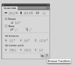
Fiddle enough with these settings, and you'll get seasick! Just remember that you can always start from scratch very easily by selecting your movie clip and clicking the Reset button in the Properties panel and the Remove Transform button in the Transform panel. In spite of the utility of this tip, you can quickly find yourself in a pickle when positioning numerous objects—not just one—in the 3D space of the stage. We hope the following suggestions make your journey a bit easier.
Parallax is an optical illusion that gives an otherwise flat 2D image the illusion of depth. We have all experienced this effect. Imaging you are sitting in your car zipping along the highway. The line in the road seem to be a blur, whereas the cows in the field move across your line of sight rather slowly and the forest in the distance behind the cows appears to hardly move at all.
Though the technique has been liberally used by science-fiction movies for years, it really didn't catch massive attention until Ken Burns, in his Public Broadcasting Service (PBS) movie The Civil War (www.pbs.org/civilwar/), used it to bring grainy black-and-white civil war photos to life. In the movie, the camera would slowly pan across an image seeming to move forward into the image or backward across the image.
The introduction of the 3D tools in Flash hands you the opportunity to create your own parallax effects in your movies. In this exercise, we are going to put a series of 2D images into motion to create the effect. Along the way, you will discover how objects can be animated in 3D space and how important movie clips are to the process of creating the illusion of parallax. Let's get started.
Note
The files used in this exercise are freely available from the NASA website (www.nasaimages.org/). The images on this site are stunning and, because they are part of the Internet archive, are available, for free, to anybody who chooses to use them for whatever purpose.
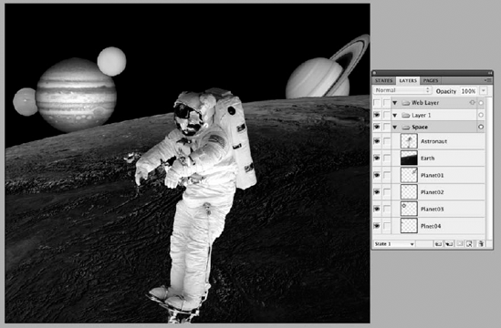
Open the
SpaceFinal.pngimage inyour Exercisefolder in Fireworks CS5 or Photoshop CS5. When the image opens, as shown in Figure 9-19, you will see that we have created the scene to be used in this project. Each of the images has been placed on its own layer, and the background for the images is transparent. Feel free to move things around. When you finish, save the file as a PNG image, and quit Fireworks or Photoshop.Open the
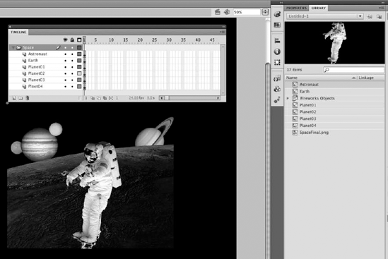
Space.flafile in yourExercisefolder. When the file opens, you will see we have imported the Fireworks image into theLibrary.In the
Propertiespanel, change the stage color to black(#000000).Open the
SpaceCompositionmovie clip found in theFireworks Objectsfolder. We are going to do a little house cleaning before we start moving stuff around.Select layer 1, and delete it from the timeline. There is nothing n this layer, so it isn't needed.
Select each object on the screen—
Astronaut,Earth, and each of the four planets—and convert them, as shown in Figure 9-20, to a movie clip.
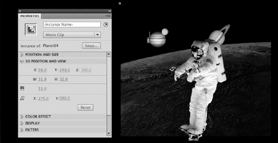
The next step in the process is to get each image positioned in 3D space. We will accomplish this by adjusting each movie clip's screen position using the z-axis. To wrap your mind about what you are going to do, think of the monitor's screen as being position zero. As you move deeper into the screen—positive numbers—the objects will appear to get smaller, and if you move away from the screen—negative numbers—the objects will appear to get bigger. This isn't the case. The objects don't resize; they either recede into the distance or appear closer to you. Let's get started:
Open the
Propertiespanel, and twirl down the3D Position and Sizeproperties. Select each object on the screen, and use the followingZvalues:Astronaut: −10Earth: 10Planet 01: 350Planet 02: 450Planet 03: 550Planet 04: 700
When you finish, the scene will look a bit different, as shown in Figure 9-21, because you have used depth to move the objects in the movie clip closer to or farther away from the surface of your computer screen.
The next step is to get the whole thing into motion and give the project the appearance of a camera panning through space.
Click the
Scene 1link to return to the main timeline. When the timeline opens, right-click frame 1, insert a motion tween, and drag the span out to frame 350.The "magic" happens here. Select the movie clip on the stage, open the
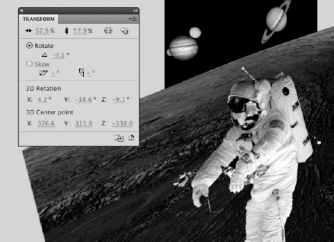
Propertiespanel, and change theX, YandZaxis settings in the3D Position and Viewarea to bring the movie clip "closer" to the viewer.Open the
Transformpanel, and in the3D Rotationarea change theX,Y, andZvalues, as shown in Figure 9-22, to create the illusion of a "fly through" and rotation.
Up to this point in the chapter, we haven't properly illustrated what the 3D center point does. Let's remedy that by showing you how to animate a pair of swinging doors. Ready to make your grand entrance?
Open the
swingDoors.flafile from theExercisefolder for this chapter. You'll see three layers in the main timeline—image,Door Right,Door Left—and a handful of items in theLibrary.Select the
3D Rotationtool, and click the movie clip that contains the left door. Hover over the center of the bull's-eye so that no letters show in the mouse pointer, and drag the bull's-eye—or use theTransformpanel—to move the 3D center point to the middle of the left side of the door, as shown in Figure 9-23.Why the left side? Because this door naturally swings on its hinges, and the 3D center point is roughly analogous to a hinge. Why the middle, rather than a corner? That's just an arbitrary choice. Given the angle of the doors, there really is no perspective. In this case, hinging the middle is the way to go. Click the movie clip that contains the right door. Reposition this movie clip's 3D center point in the upper right. This time, the hinge is on the other side, which makes sense. If you leave the 3D center point at its default value for each movie clip, the doors will spin like ballerinas.
Right-click (Windows) or Control+click (Mac) frame 1 of the
Door Leftlayer, and selectCreate Motion Tween. This converts the layer to a tween layer, but it's not quite enough.Right-click (Windows) or Control+click (Mac) the
Door Leftlayer again, and select3D Tween, which puts a check mark in that choice whenever you open the context menu again. (You can remove the check mark if you ever change your mind.)Repeat steps 2, 3, and 4 for the
Door Rightlayer.Extend the two tween layers to frame 30, and add a frame to frame 30 of the Image layer. Select the left door's movie clip, and use the
3D Rotationtool or theTransformpanel to "swing the door in" about 90 degrees (see Figure 9-24). Do the same thing for the right door.To improve the illusion, darken the doors while they're swinging in. Still at frame 30, use the
Selectiontool to select each door in turn. In thePropertiespanel, chooseBrightnessfrom theStyledrop-down list of theColor Effectarea, and set its value to−34%.To add some polish, add a new layer, and name it
Audio.Select
WindowUsing the
Selectiontool, click into frame 80 of each layer, and press the F5 key to pad out the frame span of each layer. This allows the audio to fully play out, without looping too early, when you test your movie.Select
Control
As cool as the 3D tools are, they do have a limitation in terms of how three-dimensional depth (generally the z-axis) corresponds to the stacking order of your layers, and even the stacking order of numerous symbols inside a single layer. In short, stacking order overrides 3D depth. If you drag the layer of one 3D movie clip above the layer of another 3D movie clip, the movie clip on the higher layer will always appear on top, no matter how you adjust its z index.
There are pros and cons to everything, and the pro here is that layers and in-layer symbol stacking continue to operate the way they always have. For longtime Flash users, this will feel familiar and comfortable. If you're new to Flash, this behavior may throw you for a loop, but you can work around it. The challenge arises when you want to perform a 3D tween that moves one object in front of another, when its original position was behind (and therefore obscured). Let's look at a hands-on example:
Open the
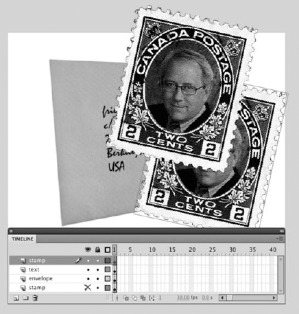
AirheadMail.flafile from theExercisefolder for this chapter. You'll see an envelope with a couple postage stamps above it, one stacked behind the other, as shown in Figure 9-25. There's another stamp in a hidden layer behind the envelope, but we'll get into that in a moment. Just be aware that both of the visible stamps are located in the same timeline layer.Select the
3D Translationtool, and click the unobscured stamp (the one on top) to select it. Adjust its z index to scale the stamp smaller and larger.In terms of 3D space, a higher z-index value seems to "push the stamp away," making it smaller. No matter how far you "push," you'll find that you cannot move the upper stamp behind the lower one. To do that, you'll have to use the old-fashioned approach.
Right-click (Windows) or Control+click (Mac) the upper stamp, and select
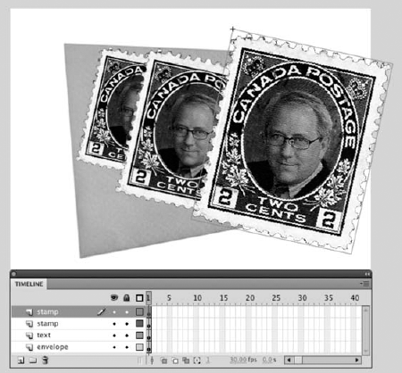
ArrangeUnhide the bottom timeline layer (named
stamp, just like the top timeline layer). This reveals a third stamp partially obscured by the envelope.Using the
3D Translationtool again, adjust the z index of either stamp in the upperstamplayer. As in step 2, nothing you do moves either stamp behind the envelope or the stamp in the bottomstamplayer.To bring the lowest stamp above the other two, you'll need to move its layer. Click the lower
stamplayer, and drag it above the otherstamplayer, as shown in Figure 9-26.This is all well and good for still compositions, but how does it work for animation? You can't very well drag layers around in the middle of a tween. The trick is to split your animation over two layers, as shown in Figure 9-27. Check out
AirheadMailAnimated.flain this chapter'sCompletefolder to see the animation in action.
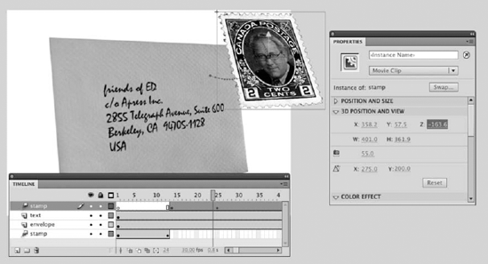
In what appears to be one smooth motion, the stamp emerges from behind the envelope, flies in front of it, and settles into place for mailing. In actuality, the magic happens at frame 14, where the movie clip abruptly ends in the lower stamp layer and reappears in the upper stamp layer to continue its above-the-envelope movement.
We began the theory part of this chapter with a cube and thought it fitting to come to a close with the same shape. (We wanted so badly to describe that as "coming full circle," but it felt like we were mixing metaphors!) For this final exercise, we're going to show you how to build a box out of a series of square movie clips. What you do with the box is up to you. We certainly hope it will spark some inspiration. In any case, we're pretty confident you'll find it motivating that you can—sort of—rotate the thing after it's built.
To really stay with the theme, we are going to use a series of images featuring the work of Toronto-based architect Will Alsop. If you ever visit Toronto and you visit the Art Gallery of Ontario, you will see what looks like a box supported on a series of colored pencils. This building is the work of Alsop and was designed as an addition to the Ontario College of Art.
Ready to be there or be square? Let's jump in:
Open
3DCube.flafrom the Chapter 9Exercisefolder. We've done the tedious part for you. TheLibrarycontains five imported JPGs, already converted to movie clip symbols.Select the five movie clips in the
Library, and drag them to the stage. Open theAlignpanel and, with all five movie clips selected, align them to the center of the stage.Now you have five copies of the same movie clip stacked on top of each other in the same layer. Why? It's because we're about to make like Henry Ford and run an assembly line. This approach will make things come together more quickly, and the precision of doing the next few steps "by the numbers" will help considerably.
Select the top movie clip, and use the
Transformpanel to change the3D Rotationarea'sZvalue to90. Now scrub theYrotation value until it hits90. This "stands up" the top movie clip and faces it west. In thePropertiespanel's3D Position and Viewarea, scrub theXvalue down to75(that's 200 pixels to the left, or half the movie clip's width).You're going to repeat this process—with different values—for the next three movie clips.
Select the next movie clip and configure it like this:
Transform Panel :3D Rotation Z= −90Transform Panel: 3D Rotation Y = −90Properties Panel: 3D Position X = 475
This movie clip now faces east and has moved half its width to the right.
Select the next movie clip and configure it like this:
Transform Panel: 3D Rotation Z = −180Transform Panel : 3D Rotation X = −90Properties Panel: 3D Position Y= 0
This movie clip now faces north (yes, this sounds like an REM song) and has moved half its height to the top.
Select the next movie clip and configure it like this:
Transform Panel : 3D Rotation Z= 0 (no change)Transform Panel: 3D Rotation X = 90Properties Panel: 3D Position Y= 400
This movie clip now faces south and has moved half its height to the bottom.
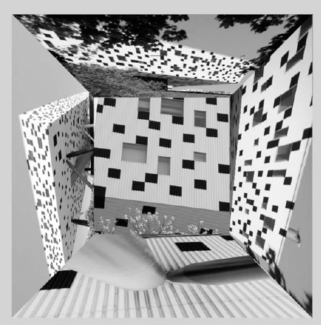
At this point, you're essentially looking down into the cube (see Figure 9-28). Although it may not appear to be, the image at the bottom of the cube is already halfway up the cube. The reason the depth looks wrong is because of the stacking order of these movie clips.
Right-click (Windows) or Control+click (Mac) the right (east) movie clip, and select
ArrangeWhy restack them in that particular order? It's because we're about to tilt the box forward, which means we'll be looking at what's currently the south wall. The movie clip currently on top of the stack—building above the trees—needs to be moved "toward you" first, though.
Select the movie clip that appears to be "inside the stack, and set its
3D Position Zvalue to−200.Click frame 1 in the timeline to select all the 3D objects simultaneously. With all the movie clips selected, click the one showing (this puts the
Propertiespanel where you want it), and change the3D Position Zvalue to0. This moves the whole collection "back" toward the stage.In the
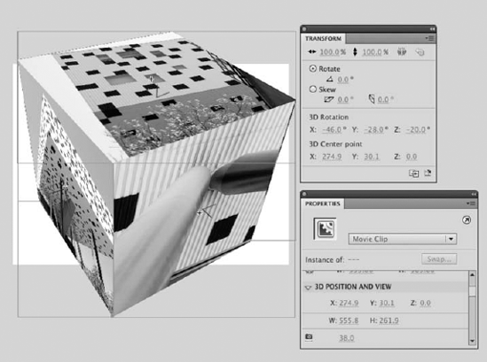
Transformpanel, change the3D Rotation Xvalue to−46and the3D Rotation Yvalue to−28.In the
Propertiespanel, just above theVanishing pointvalues, you'll see a setting we visited on our trip to that street in Amsterdam. It has a camera icon, and if you hover over that, you'll get a tooltip that saysPerspective angle. Scrub thePerspective anglevalue from its default55down to38. See how that relaxes the slight fish-eye lens effect?Change the
3D Rotation Zvalue to−20to straighten out your box. You'll get something like the cube shown in Figure 9-29.
Whatever angle you approach it from, 3D manipulation in Flash is a ton of fun! While you still have your 3DCube.fla file open, we encourage you to keep experimenting. With all the movie clips selected, use the 3D Rotation tool to see what happens when you spin that cube all the way around (you'll see the stacking order limitation again).
What happens if you scrub Perspective angle all the way down to 1? How about over a 100? How does the Vanishing point setting affect things? Can you convert the selected movie clips—all five of them—into a new movie clip? (Hint: Absolutely!) When you do, can you arrange two or more movie clips of the completed box on the stage? (You betcha.)
We could keep going, but we hope you're excited enough to take it from here.
In this chapter, you learned the following:
The rudiments of perspective drawing, including the concept of the vanishing point
How to use the
3D Rotationand3D TranslationtoolsHow to use the
Property inspectorandTransformpanel in conjunction with the 3D toolsSome workflow tips on arranging objects in Flash 3D space
One of the authors has been fond of anything related to 3D for years. In fact, he keeps a pair of red-and-blue anaglyph glasses on top of his monitor—you know, for watching those cheesy 1950s science fiction movies in 3D. Speaking of movies, sci-fi or otherwise, Flash is pretty hip on cinema too. In fact, one of the hottest features of Flash in the past couple years is its video capabilities, which now include high-definition, full-screen support. Ready to jam like Cecil B. DeMille? You just have to turn the page.