
4
HEAVY TIMBER FRAME CONSTRUCTION
• Fire-Resistive Heavy Timber Construction
![]()
CONSIDERATIONS OF SUSTAINABILITY IN HEAVY TIMBER CONSTRUCTION
![]()
Wood Shrinkage in Heavy Timber Construction
Anchorage of Timber Beams and Masonry Walls
Floor and Roof Decks for Heavy Timber Buildings
• Combustible Buildings Framed with Heavy Timber
• Lateral Bracing of Heavy Timber Buildings
• Building Services in Heavy Timber Buildings
• Longer Spans in Heavy Timber
Large Beams
Rigid Frames
Trusses
Arches and Domes
![]()
FOR PRELIMINARY DESIGN OF A HEAVY TIMBER STRUCTURE
![]()
• Heavy Timber and the Building Codes
• Uniqueness of Heavy Timber Framing
Architect Nils Finne combines heavy timber framing with robust stonework and finely detailed exterior finish carpentry in this well-crafted residence. (Architect: FINNE Architects www.FINNE.com; photograph by Art Grice)
Wood beams have been used to span roofs and floors of buildings since the beginning of civilization. The first timber-framed buildings were crude pit houses, lean-tos, teepees, and basketlike assemblages of bent saplings. In earliest historic times, roof and floor timbers were combined with masonry loadbearing walls to build houses and public buildings. In the Middle Ages, braced wall frames of timber were built for the first time (Figures 4.1 and 4.2). The British carpenters who emigrated to North America in the 17th and 18th centuries brought with them a fully developed knowledge of how to build efficiently braced frames, and for two centuries North Americans lived and worked almost exclusively in buildings framed with hand-hewn wooden timbers joined by interlocking wood-to-wood connections (Figures 4.3 and 4.4). Nails were rare and expensive, so they were used only in door and window construction and, sometimes, for fastening siding boards to the frame.
Until two centuries ago, logs could be converted to boards and timbers only by human muscle power. To make timbers, axemen skillfully scored and hewed logs to reduce them to a rectangular profile. Boards were produced slowly and laboriously with a long, two-man pit saw, one man standing in a pit beneath the log, pulling the saw down, and the other standing above, pulling it back up. At the beginning of the 19th century, water-powered sawmills began to take over the work of transforming tree trunks into lumber, squaring timbers and slicing boards in a fraction of the time that it took to do the same work by hand.
Most of the great industrial mills of 19th-century North America, which manufactured textiles, shoes, machinery, and all the goods of civilization, consisted of heavy sawn timber floors and roofs supported by masonry exterior walls (Figures 4.5 and 4.6). The house builders and barn raisers of the early 19th century switched from hand-hewn to sawn timbers as soon as they became available. Many of these mills, barns, and houses still survive, and with them survives a rich tradition of heavy timber building that continues to the present day.
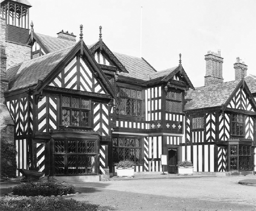
FIGURE 4.1 Braced wall framing was not developed until the late Middle Ages and early Renaissance, when it was often exposed on the face of the building in the style of construction known as halftimbering. The space between the timbers was filled with brickwork or with wattle and daub, a crude plaster of sticks and mud, as seen here in Wythenshawe Hall, a 16th-century house near Manchester, England. (Photo by James Austin, Cambridge, England)
FIGURE 4.2 European timber house forms generally followed a progression of development from crude pit dwellings, made of earth and tree trunks, to cruck frames, to braced frames. The crucks (curved timbers), hewn by hand from appropriately shaped trees, were precursors to the laminated wood arches and rigid frames that are widely used today.
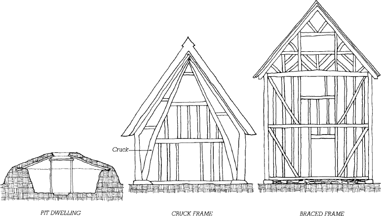
FIGURE 4.3 The European tradition of heavy timber framing was brought to North America by the earliest settlers and was used for houses and barns until well into the 19th century. (Drawing by Eric Sloane; courtesy of the artist)
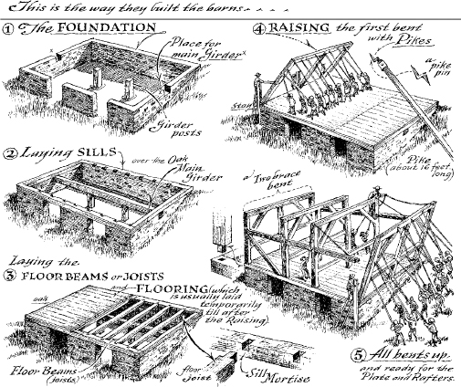
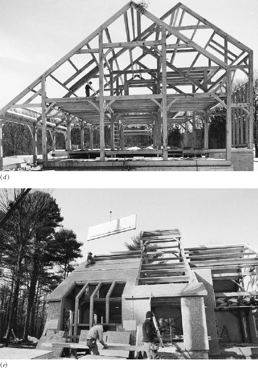
FIGURE 4.4 Traditional timber framing has been revived in recent years by a number of builders who have learned the old methods of joinery and updated them with the use of modern power tools and equipment. (a) Assembling a bent (a plane of columns, beams, rafters, and braces). (b) The completed bents are laid out on the floor, ready for raising. (c) Raising the bents, using a truck-mounted crane, and installing floor framing and roof purlins (smaller, secondary framing members that span across the primary beams or rafters). (d) The completed frame. (e) Enclosing the timber-framed house with sandwich panels consisting of waferboard faces bonded to an insulating foam core. (Courtesy of Benson Woodworking, Inc., Alstead, New Hampshire)

The old country builder, when he has to get out a cambered beam or a curved brace, goes round his yard and looks out the log that grew in the actual shape, and taking off two outer slabs by handwork in the sawpit, chops it roughly to shape with his side-axe and works it to the finished face with the adze, so that the completed work shall for ever bear the evidence of his skill . . .
Gertrude Jekyll, English garden designer, writing in 1900.
FIGURE 4.5 Most 19th-century industrial buildings in North America were constructed of heavy timber roofs and floors supported at the perimeter on masonry loadbearing walls, a construction method that came to be known to as Mill construction. This impressive group of textile mills stretches for a distance of 2 miles (3 km) along the Merrimac River in Manchester, New Hampshire. (Photo by Randolph Langenbach)

FIGURE 4.6 The generously sized windows in the mills provided plenty of daylight to work by. Columns were of wood or cast iron. Most New England mills, like this one, were framed very simply: Their floor decking is carried by beams running at right angles to the exterior walls, supported at the interior on two lines of columns. Notice that the finish flooring runs perpendicular to the structural decking. Overhead sprinklers provide additional fire safety to a construction method that already has inherent fire-resistive qualities. (Photo by Randolph Langenbach)

FIRE-RESISTIVE HEAVY TIMBER CONSTRUCTION
Large timbers, because of their greater capacity to absorb heat, are much slower to catch fire and burn than smaller pieces of wood. When exposed to fire, a heavy timber beam, though deeply charred by gradual burning, will continue to support its load long after an unprotected steel beam exposed to the same conditions has collapsed. If the fire is not prolonged, a fire-damaged heavy timber beam or column can often be sandblasted afterward to remove the surface char and continue in service. For these reasons, building codes recognize heavy timber framing that meets certain specific requirements as having fire-resistive properties.
In the International Building Code (IBC), for a building to be classified as Type IV Heavy Timber (HT) construction, its wooden structural members must meet certain minimum size requirements and its exterior walls must be constructed of noncombustible materials. Minimum permitted sizes for solid wood timbers are summarized in Figure 4.7. Glue-laminated members used in this type of construction must meet similar requirements. Exterior walls may be constructed of concrete, masonry, or metal cladding. Historically, this combination of fire-resistive wood framing and noncombustible exterior was referred to as Mill construction, reflecting its origins in 19th-century brick masonry mill structures, or as Slow-burning construction (Figures 4.8–4.11). Traditionally, the edges of the timbers were also chamfered (beveled at 45 degrees) to eliminate the thin edges of wood that catch fire most easily, but this is no longer a code requirement.
CONSIDERATIONS OF SUSTAINABILITY IN HEAVY TIMBER CONSTRUCTION
In addition to the issues of sustainability of wood production and use that were raised in the previous chapter, there are issues that pertain especially to heavy timber frame construction:
It is wasteful to saw large, solid timbers from logs:
In most instances, only one or two timbers can be obtained from a log, and it is often difficult to saw smaller boards from the leftover slabs.
Glue-laminated timbers and composite timbers utilize wood fiber much more efficiently than solid timbers.
Recycled timbers from demolished mills, factories, and barns are often available. Most of these are from old-growth forests in which trees grew slowly, producing fine-grained, dense wood. As a result, many have structural properties that are superior to those of new-growth timbers. Recycled timbers may be used as is, resurfaced to give them a new appearance, or resawn into smaller members. However, they often contain old metal fasteners. Unless these are meticulously found and removed, they can damage saw blades and planer knives, causing expensive mill shutdowns while repairs are made.
Continuous bending action of beams may be created by splicing beams at points of inflection rather than over supports, as shown in Figures 4.15, 4.20 and 4.21. This reduces maximum bending moments, allowing timber sizes to be reduced substantially.
Timbers do not lose strength with age, although they do sag progressively if they are overloaded. When a heavy timber building is demolished at some time in the future, its timbers can be recycled, even if they were obtained as recycled material for the building that is being demolished.
A heavy timber frame enclosed with foam core sandwich or stressed-skin panels is relatively airtight and well insulated, with few thermal bridges. Heating and cooling of the building will consume relatively little energy.
The glues and finish coatings used with glue-laminated timbers may give off gases such as formaldehyde that can cause indoor air quality (IAQ) problems. It is wise to determine in advance what glues and coatings are to be used, and to avoid ones that may cause IAQ problems.
Wood Shrinkage in Heavy Timber Construction
Where the edges of floors and roofs of a heavy timber frame are supported on concrete or masonry, special attention must be given to the potential for differential shrinkage between the outer walls and the interior wood column supports. Wood, compared to masonry or concrete, expands and contracts more with changes in moisture content, particularly in the direction perpendicular to its grain. These changes occur over a period of years as large timbers gradually dry and seasonally with changes in ambient conditions. A heavy timber frame building is detailed to minimize the effects of this differential shrinkage by eliminating cross-grain wood from the interior lines of support. In traditional Mill construction, cast iron pintles or steel caps carry the column loads past the cross-grain of the beams at each floor, so that the beams and girders can shrink without causing the floors and roof to sag (Figures 4.8 and 4.9). In contemporary practice, a glue-laminated column may be fabricated as a single piece running the entire height of the building, with the beams connected to the column by wood bearing blocks or welded metal connectors; or columns may be butted directly to one another at each floor with the aid of metal connectors (Figures 4.13, 14.14, and 4.17).
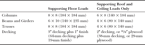
FIGURE 4.7 Minimum sizes for solid wood members used in Type IV Heavy Timber construction, as specified in the IBC.
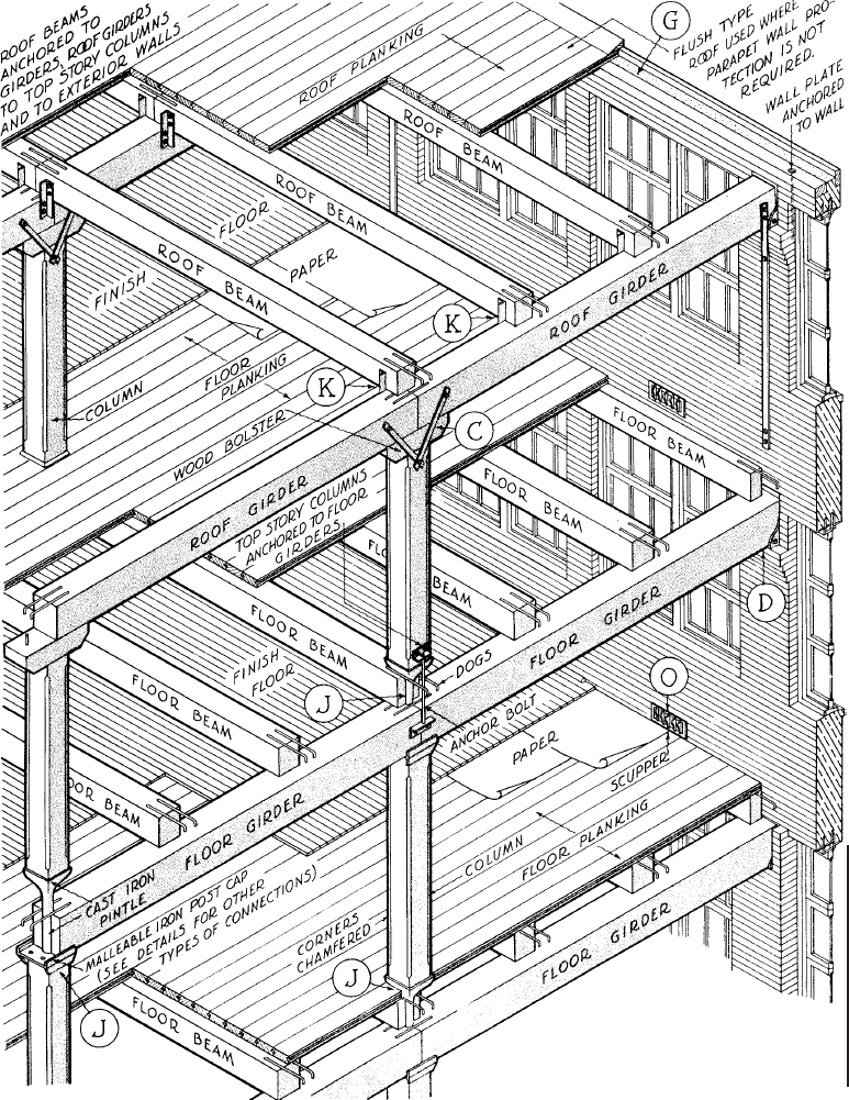
FIGURE 4.8 Traditional Mill construction bypasses problems of wood shrinkage at the interior lines of support by using cast iron pintles (see the lower connection detail in the left-most column in the illustration) to transmit the column loads through the beams and girders. Iron dogs tie the beams together over the girders. A long steel strap anchors the roof girder to a point sufficiently low in the outside wall that the weight of the masonry above the anchorage point is enough to resist wind uplift on the roof. (Heavy timber construction details courtesy of the National Forest Products Association, Washington, DC)
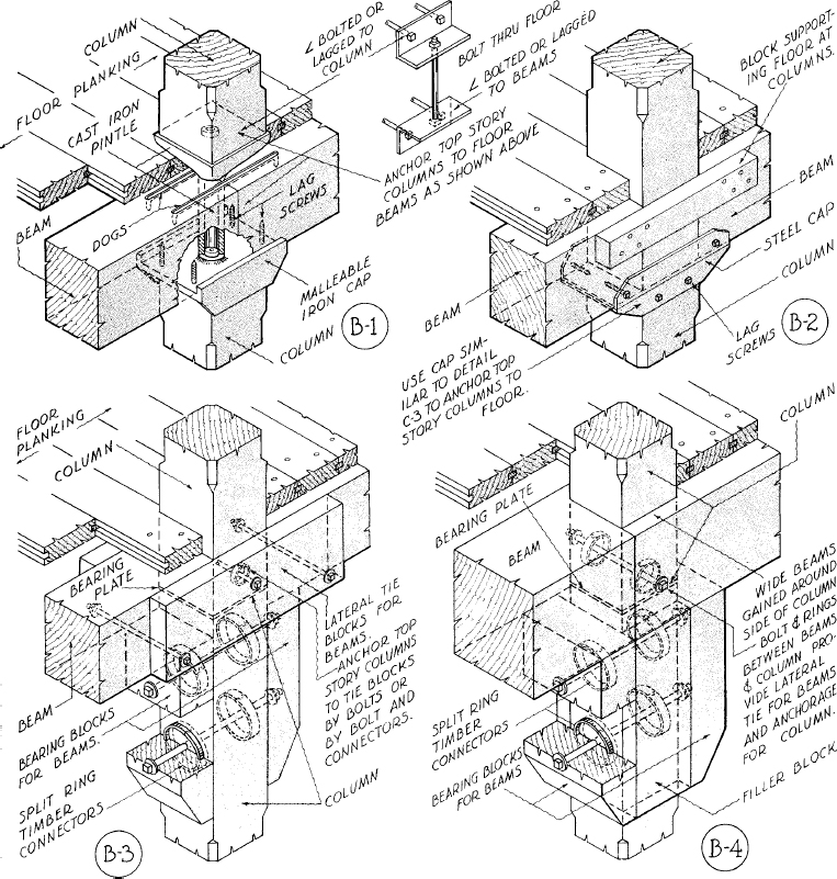
FIGURE 4.9 Four alternative details for interior girder–column intersections. Detail B-1 avoids wood shrinkage problems with an iron pintle, while the other three details bring the columns through the beams with only a steel bearing plate between the ends of the column sections. Split-ring connectors are used in the lower two details to form a strong enough connection between the bearing blocks and the columns to support the loads from the beams; it would take a much larger number of bolts to do the same job. (Heavy timber construction details courtesy of the National Forest Products Association, Washington, DC)
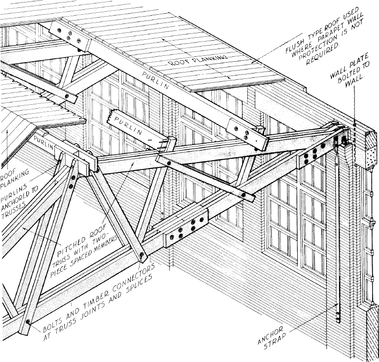
FIGURE 4.10 Heavy timber roof trusses for Mill construction. Split-ring connectors are used to transmit the large forces between the overlapping members of the truss. A long anchor strap is again used at the outside wall, as explained in the legend to Figure 4.8. (Heavy Timber construction details courtesy of the National Forest Products Association, Washington, DC)
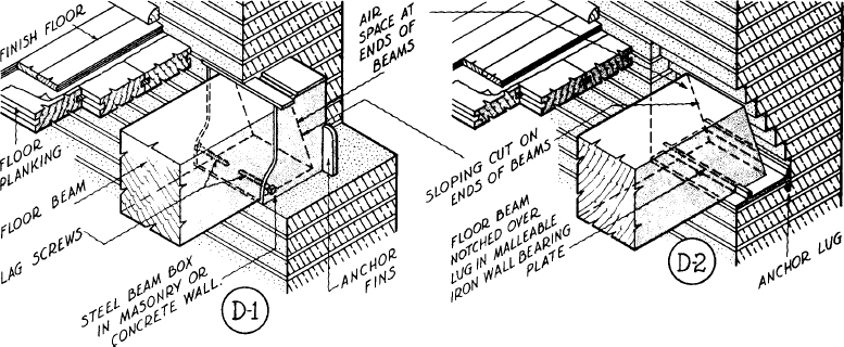
FIGURE 4.11 Two alternative details for the bearing of a beam on masonry in traditional Mill construction. In each case, the beam end is firecut to allow it to rotate out of the wall if it burns through (Figure 4.12), but it is also anchored against pulling away from the wall by means of either lag screws or a lug on the iron bearing plate. (Heavy timber construction details courtesy of the National Forest Products Association, Washington, DC)

FIGURE 4.12 A timber beam that burns through in a prolonged fire is likely to topple its supporting masonry wall (left) unless its end is firecut (right). In this illustration, the beam is anchored to the wall in each case by a steel strap anchor.
FIGURE 4.13 An example of contemporary heavy timber construction, based on steel plate connectors and an insulated cavity wall.
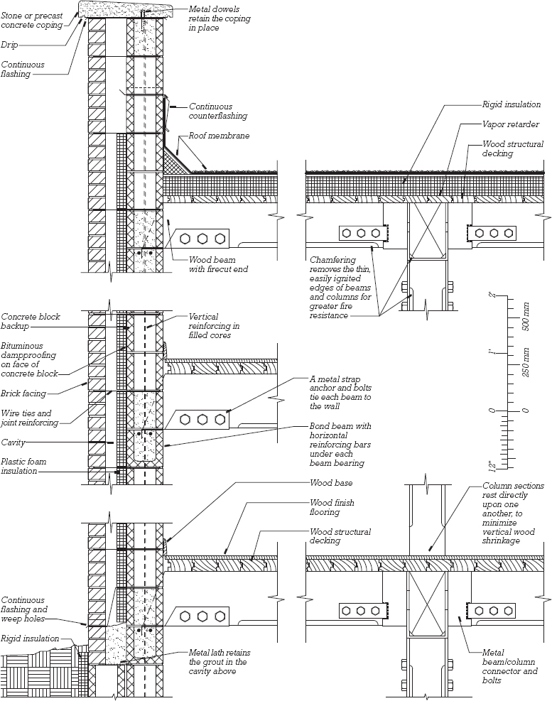

FIGURE 4.14 Some typical beam–column connections for contemporary heavy timber construction. The first three examples are for double beams sandwiched on either side of the column, and the fourth shows single beams in the same plane as the column. In the shoulder bearing connection, the beams are recessed into the column by an amount that allows the load to be transferred safely by wood-to-wood bearing; the bolts serve only to keep the beams in the recesses. Bearing blocks allow more bolts to be inserted in a connection than can fit through the beams, and each bolt in the bearing blocks can hold several times as much load as one through the beam because it acts parallel to the grain of the wood rather than perpendicular. It is generally impossible to place enough bolts in a beam–column joint to transfer the load successfully without bearing blocks unless split rings are used, as shown in the third example. The steel straps and bolts in the fourth example hold the beams on the bearing blocks.
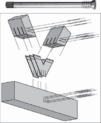
FIGURE 4.15 This contemporary heavy timber fastening system uses proprietary self-drilling steel dowels (top) in combination with embedded steel plates spanning the joint between members to create high-strength connections. The type of joint diagrammed in the lower portion of this figure can be used as a substitute for the lapped members and split-ring connectors illustrated in Figure 4.10. (Courtesy of SFS intec, Inc., Wyomissing, PA, www.sfsintecusa.com)

FIGURE 4.16 A completed heavy timber truss joint using the fastening system illustrated in the previous figure. (Courtesy of SFS intec, Inc., Wyomissing, PA, www.sfsintecusa.com)
FIGURE 4.17 Typical connections for a contemporary glue-laminated wood frame. The cantilevered beam and hinge connector save wood by connecting the beams at points of zero bending moment rather than at the columns to take full advantage of continuous bending action in the beams.

Anchorage of Timber Beams and Masonry Walls
Where heavy timber beams join masonry or concrete walls, three problems must be solved: First, the beam must be protected from decay caused by moisture seeping through the wall. This is done by leaving a ventilating airspace of at least ½ inch (13 mm) between the masonry and all sides of the beam except the bottom, unless the beam is chemically treated to resist decay. The second and third problems have to be solved together: The beam must be securely anchored to the wall so that it cannot pull away under normal service, yet it must be able to rotate freely so that it does not pry the wall apart if it burns through and collapses during a severe fire (Figure 4.12). Traditional and more contemporary methods of accomplishing these dual needs are shown in Figures 4.11 and 4.13, respectively.
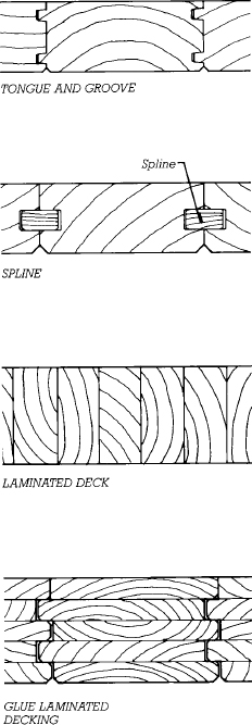
FIGURE 4.18 Large-scale cross sections of four types of Heavy Timber decking. Tongue-and-groove decking is the most common, but the other three types are slightly more economical of lumber because wood is not wasted in the milling of the tongues. Laminated decking is a traditional type for longer spans and heavier loads; it consists of ordinary dimension lumber laid on edge and spiked together. Glue-laminated decking is a modern type. In the example shown here, five separate boards are glued together to make each piece of decking. Decking of any type is usually furnished and installed in random lengths. The end joints do not necessarily line up over beams; rather, they are staggered to avoid creating zones of structural weakness. The splines, tongues, or nails allow the narrow strips of decking to share concentrated structural loads as if they constituted a continuous sheet of solid wood.
Floor and Roof Decks for Heavy Timber Buildings
Building codes require that Type IV Heavy Timber buildings have floors and roofs of solid wood construction without concealed cavities. Figure 4.18 shows different types of decking used for these purposes. Minimum permissible thicknesses of decking are given in Figure 4.7. To meet code requirements, floor decking must also be covered with a finish floor consisting of nominal 1-inch (19-mm) tongue-and-groove boards laid at right angles or diagonally to the structural decking. In some circumstances, ½-inch (13-mm) plywood or other composite wood panels are also permitted as the finish layer.
COMBUSTIBLE BUILDINGS FRAMED WITH HEAVY TIMBER
Heavy timber members may also be used in buildings that do not meet the building code definition of Type IV Heavy Timber construction. They may be used in combination with smaller wood framing members or in buildings with exterior walls of combustible construction. These buildings, classified under the IBC as Type V (Wood Light Frame) construction, bring the architectural qualities and structural performance of beam-and-decking framing to smaller, residential, commercial, religious, and institutional buildings. In these applications, there are no restrictions (other than structural) on the minimum size of timbers, minimum thickness of decking, or exterior wall material, and light framing of nominal 2-inch (38-mm) lumber can be incorporated as desired.
LATERAL BRACING OF HEAVY TIMBER BUILDINGS
A heavy timber frame building with an exterior masonry or concrete bearing wall is normally braced against wind and seismic forces by the shear resistance of its exterior walls, working together with the diaphragm action of its roof and floor decks. In areas of high seismic risk, the walls must be heavily reinforced both vertically and horizontally, and the decks may have to be specially nailed or overlaid with plywood to increase their shear resistance, as well as specially anchored to the perimeter walls. In buildings with framed exterior walls, diagonal bracing or shear panels must be provided. Seismic upgrades to historic heavy timber and masonry buildings often require the insertion of new steel-braced frames or reinforced concrete shear walls in order to meet contemporary lateral force resistance requirements.
BUILDING SERVICES IN HEAVY TIMBER BUILDINGS
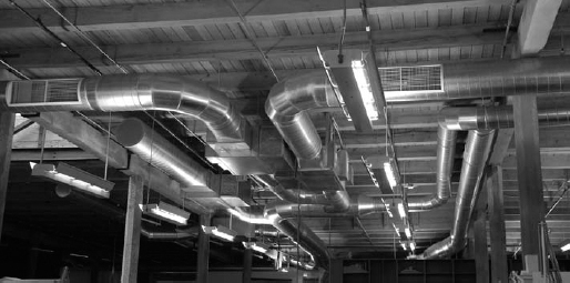
The heavy timber structure poses some special problems for the designer because the exposed framing and decking do not provide the concealed cavities that are present in light frame structures and other conventional building systems. Roof thermal insulation cannot be hidden in spaces between ceiling joists or roof rafters and, instead, must be placed on top of the roof deck. If the roof is nearly flat, it can be insulated and roofed in the manner shown for low-slope roofs in Chapter 16, or, if the roof is steeply pitched, a nailing surface for the shingles or other roofing must be added on the outside of the insulation. Electrical wiring for lighting fixtures that are mounted on the underside of the decking must either run through exposed metal conduits below the deck, which may be visually unsatisfactory, or be channeled through the insulation above the deck. Ductwork for heating and cooling must remain exposed. If the walls and partitions are made of masonry or stressed-skin panels, special arrangements are necessary for installing wiring, plumbing, and mechanical system components in the walls as well (Figure 4.19).
FIGURE 4.19 When floors and roofs are heavy timber framed, lighting, communications wiring, ductwork, fire sprinklers, and other services are exposed to view. (Photo by Joseph Iano)
LONGER SPANS IN HEAVY TIMBER
For buildings that require spans longer than 20 to 30 feet (6 to 9 m), the maximum usually associated with framing of sawn timbers, the designer may select from among several alternative types of timber structural devices.
FIGURE 4.20 Installing tongue-and-groove roof decking over laminated beams and girders. (Courtesy of American Institute of Timber Construction)

Large Beams
With large, old-growth trees no longer readily available, very large timber beams are usually built up of laminations or strands rather than sawn. Such beams are stronger and more dimensionally stable than sawn wood beams and can be made in the exact size and shape desired (Figures 4.20 and 4.21). Hybrid or FRP reinforced glulam beams, as described in Chapter 3, can be useful when especially longer span are needed or heavy loads must be supported.
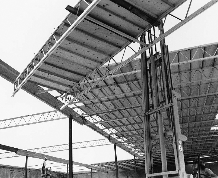
FIGURE 4.21 This roof uses glue-laminated beams to support proprietary long-span trusses made of wood with steel tube diagonals. Notice that the beams are hinged in the manner shown in Figure 4.17. The trusses, roof joists, and plywood roof deck are prefabricated into panels to reduce installation time. (Courtesy of Trus Joist MacMillan)
Rigid Frames
The cruck (Figure 4.2), cut from a bent tree, was a form of rigid frame or portal frame. Today's rigid frames are glue-laminated to shape and find wide use in longer-span buildings. Standard configurations are readily available (Figures 4.22–4.24), or the designer may order a custom shape. Rigid frames exert a horizontal thrust, so they must be tied together at the base with steel tension rods, also called tie rods. In laminated wood construction, rigid frames are often called arches, acknowledging that the two structural forms act in very nearly the same manner.
Trusses
The majority of wood trusses built each year are light roof trusses of nominal 2-inch (38-mm) lumber joined by toothed plates (see Figures 3.44, 3.47, 5.65, and 5.66). For larger buildings, however, heavy timber trusses may be used. Their joints are made with steel bolts and welded steel plate connectors or splitring connectors. Sawn, laminated, and structural composite timbers are used, sometimes in combination with steel rod tension members. Many shapes of heavy timber truss are possible, and spans of over 100 feet (30 m) are common (Figures 4.10 and 4.25–4.28).

FIGURE 4.22 Three-hinged arches of glue-laminated wood carry laminated wood roof purlins. The short crosspieces of wood between the purlins are temporary ladders for workers. (Courtesy of American Institute of Timber Construction)

FIGURE 4.23 Typical details for three-hinged arches of laminated wood. The tie rod is later covered by the floor slab.

FIGURE 4.24 The shear plates in the crown connection of the arch, shown here in a larger-scale detail, are recessed into grooves in the wood and serve to spread any force from the steel rod across a much wider surface area of wood to avoid crushing and splitting.

FIGURE 4.25 A heavy timber roof truss with steel rod tension members. This type of truss is easy to construct but cannot be used if predicted wind uplift forces are sufficiently strong to cause the forces in the tension members to reverse (such slender steel rods cannot resist compressive forces). The center splice in the lower chord of the truss is required only if it is impossible to obtain single pieces of lumber long enough to reach from one end of the truss to the other. Compare this mode of truss construction with that shown in Figures 4.10, 4.15, and 4.16; still another common mode is to form the truss of a single layer of heavy members connected by steel side plates and bolts, as shown in Figures 4.27 and 4.28.

FIGURE 4.26 Laminated wood roof trusses with steel connector plates. The steel rods are for lateral stability, to keep the bottom chords of the trusses from moving sideways. (Woo & Williams, Architects. Photographer: Richard Bonarrigo)

FIGURE 4.27 Roof trusses for the Montville, New Jersey, Public Library consist of a single plane of glue-laminated members joined by custom-designed steel side plates and bolts. An extensive scheme of diagonal bracing resists wind and seismic forces in both axes of the building.
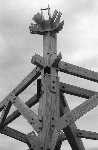
FIGURE 4.28 The Montville Public Library timbers are joined with custom-designed connectors that are welded together from steel plates. (Design and photographs by Eliot Goldstein, The Goldstein Partnership, Architects)
Arches and Domes
Long curved timbers for making heavy timber vaults and heavy timber domes are easily fabricated in laminated wood and are widely used in athletic arenas, auditoriums, suburban retail stores, warehouses, and factories (Figures 4.29–4.31). Arched structures, like rigid frames, exert lateral thrusts that must be countered by tie rods or suitably designed foundations.
FIGURE 4.29 Semicircular laminated wood arches support the timber roof of the Back Bay Station in Boston. Notice the use of horizontal steel tie rods to resist the thrust of the arches at the base. (Architects: Kallmann, McKinnell & Wood. Photo © Steve Rosenthal)


FIGURE 4.30 A typical hinged foundation connection for an arch or dome, made of welded steel plates. The hinge pin allows for rotation between the arch and the foundations, which avoids many kinds of forces that might otherwise be placed on the structure by wood shrinkage and foundation movement.

FIGURE 4.31 This laminated wood dome spans 530 feet (161.5 m) to cover a 25,000-seat stadium and convention center in Tacoma, Washington. (Architects: McGranahan, Messenger Associates. Structural engineers: Chalker Engineers, Inc. Photo by Gary Vannest. Courtesy of American Wood Council)
FOR PRELIMINARY DESIGN OF A HEAVY TIMBER STRUCTURE
• Estimate the nominal depth of wood roof decking at ![]() of its span. Estimate the depth of wood floor decking at
of its span. Estimate the depth of wood floor decking at ![]() of its span. Standard nominal depths of wood decking are 2, 3, 4, 6, and 8 inches (actual size 38, 64, 89, 140, and 184 mm).
of its span. Standard nominal depths of wood decking are 2, 3, 4, 6, and 8 inches (actual size 38, 64, 89, 140, and 184 mm).
• Estimate the depth of solid wood beams at ![]() of their span and the depth of glue-laminated beams at
of their span and the depth of glue-laminated beams at ![]() of their span. Add a nominal 6 inches (150 mm) to these depths for girders. The width of a solid wood beam or girder is usually ¼ to ½ of its depth. The width of a glue-laminated beam typically ranges from
of their span. Add a nominal 6 inches (150 mm) to these depths for girders. The width of a solid wood beam or girder is usually ¼ to ½ of its depth. The width of a glue-laminated beam typically ranges from ![]() to ¼ of its depth.
to ¼ of its depth.
• Estimate the depth of timber triangular roof trusses at ![]() to ½ of their span and the depth of bowstring trusses at ½ to ⅔ of their span.
to ½ of their span and the depth of bowstring trusses at ½ to ⅔ of their span.
• To estimate the size of a wood column, add up the total roof and floor area supported by the column. A nominal 6-inch (actual size 140 mm) column can support up to about 400 square feet (37 m2) of area, an 8-inch (actual size 184 mm) column 1000 square feet (93 m2), a 10-inch (actual size 235 mm) column 1500 square feet (140 m2), a 12-inch (actual size 286 mm) column 2500 square feet (230 m2), and a 14-inch (actual size 337 mm) column 3500 square feet (325 m2). Wood columns are usually square or nearly square in proportion.
For actual sizes of solid timbers in conventional units, see Figures 3.22 and 3.23. Standard sizes of glue-laminated timbers are given in Chapter 3. For a building that must qualify as Type IV Heavy Timber construction under the IBC, minimum timber sizes are given in Figure 4.7.
These approximations are valid only for purposes of preliminary building layout, and must not be used to select final member sizes. They apply to the normal range of building occupancies such as residential, office, commercial, and institutional buildings. For manufacturing and storage buildings, use somewhat larger members.
For more comprehensive information on preliminary selection and layout of a structural system and sizing of structural members, see Edward Allen and Joseph Iano, The Architect's Studio Companion (4th ed.), New York, John Wiley & Sons, Inc., 2007.
HEAVY TIMBER AND THE BUILDING CODES
The table in Figure 1.2 shows the range of height and area limits for buildings of different occupancies built of Heavy Timber (Type IV) construction and of Light Frame (Type V) construction (applicable when heavy timber framing and light frame construction are mixed). Notice that when considering any particular occupancy, the allowable heights and areas for Heavy Timber construction are comparable to those for 1-Hour-Protected Noncombustible (Type IIA) construction (steel, concrete, or masonry) and are greater than those for protected and unprotected Type V construction or unprotected steel (Type IIB). These limits are an explicit recognition of the inherent fire-resistive qualities of heavy timber framing. (Recall also that allowable floor areas in this table can be increased by installing an automatic fire suppression sprinkler system in the building, as outlined in Chapter 1 of this book.)

FIGURE 4.32 Architects Greene and Greene of Pasadena, California, were known for their carefully wrought expressions of timber framing in houses such as this one, built for David B. Gamble in 1909. (Photo by Wayne Andrews)
UNIQUENESS OF HEAVY TIMBER FRAMING
Heavy timber cannot span as far or with such delicacy as steel, and it cannot mimic the structural continuity or smooth shell forms of concrete, yet many people respond more positively to the idea of a timber building than they do to one of steel or concrete. To some degree, this response may stem from the color, grain figure, and warmer feel of wood. In part, it may also come from the pleasant associations that people have with the sturdy, satisfying houses our ancestors erected from hand-hewn timbers only a few generations ago. Most people today live in dwellings where none of the framing is exposed. Exposed ceiling beams in one's house or apartment are considered an amenity, and shopping or restaurant dining in a converted mill building of heavy timber and masonry construction is generally thought to be a pleasant experience. There is something in all of us that derives satisfaction from seeing wood beams at work.

FIGURE 4.33 Dramatic exposed timber scissor trusses support a steeply sloping roof structure in this vacation cabin designed by Nils Finne in the North Cascade Mountains of Washington State. (Architect: FINNE Architects www.FINNE.com; photograph by Art Grice)
In economic reality, heavy timber must compete successfully on the basis of price with other construction materials, and as our forests have diminished in quality and shipping costs have risen, timber is no longer an automatic choice for building a mill or any other type of structure. For many buildings, however, heavy timber is an economical alternative to steel and concrete, particularly in situations where the appearance and feel of its large wooden members will be highly valued by those who use it, in regions close to commercial forests, or where code provisions or fire insurance premiums create a financial incentive.
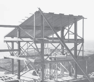
FIGURE 4.34 Each of the attached dwellings in Sea Ranch Condominium #1 at Sea Ranch, in northern California, built in 1965, is framed with a simple cage of unplaned timbers sawn from trees taken from another portion of the site. The diagonal members are wind braces. (Architects: Moore, Lyndon, Turnbull, and Whitaker. Photo by Edward Allen)
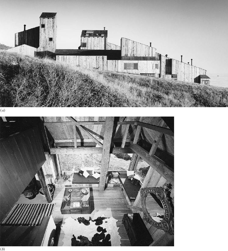
FIGURE 4.35 (a) The exterior of Sea Ranch Condominium #1, an interior view of which is shown in the opening photograph of this chapter, is sheathed with vertical 2-inch (38-mm) unplaned tongue-and-groove decking and clad with ¾-inch (19-mm) tongue-and-groove redwood siding. (b) Another view of the exposed timbers and connectors inside a dwelling in this building. The flooring is vertical-grain Douglas fir. (Photos © Morley Baer)
SELECTED REFERENCES
1. American Institute of Timber Construction. Timber Construction Manual (5th ed.). New York, John Wiley & Sons, Inc., 2004.
This is a comprehensive design handbook for timber structures, including detailed engineering procedures as well as general information on wood and its fasteners.
2. American Institute of Timber Construction. Typical Construction Details. AITC 104–2003. Englewood, CA, 2003.
This 32-page reference contains dozens of examples of how to detail connections in heavy timber buildings. Especially instructive are the bad examples that are presented as lessons in what to avoid. This reference can also be viewed for free on the American Institute of Timber Construction's web site, www.aitc-glulam.org.
3. Benson, Tedd. Timber-Frame Home: Design, Construction and Finishing. Middletown, CT, Taunton Press, 1997.
The author is one of the most experienced traditional timber framers in the world. This is a comprehensive, richly illustrated, authoritative guide to timber house construction.
4. Goldstein, Eliot E. Timber Construction for Architects and Builders. New York, McGraw-Hill, 1998.
This thoroughly practical book is based on the author's firsthand experience in designing timber structures, as well as recognized timber engineering practice.
WEB SITES
Heavy Timber Frame Construction
Author's supplementary website: www.ianosbackfill.com/04_heavy_timber_frame_construction
American Institute of Timber Construction: www.aitc-glulam.org
American Wood Council: www.awc.org
Canadian Wood Council: www.cwc.ca
Timber Framers Guild: www.tfguild.org
KEY TERMS AND CONCEPTS
REVIEW QUESTIONS
1. Why does Heavy Timber construction receive relatively favorable treatment from building codes and insurance companies?
2. What are the important factors in detailing the junction of a wood beam with a masonry loadbearing wall? Draw several ways of making this joint.
3. Draw from memory one or two typical details for the intersection of a wood column with a floor of a building of Heavy Timber construction.
EXERCISES
1. Determine from the code table in Figure 1.2 whether a building you are currently designing could be built of Heavy Timber construction and what modifications you might make in your design so that it will conform to the requirements of Heavy Timber construction.
2. Find a barn or mill that was constructed in the 18th or 19th century and sketch some typical connection details. How is the structure stabilized against horizontal wind forces?
3. Obtain a book on traditional Japanese construction from the library and compare Japanese timber joint details with 18th- or 19th-century American practice.