Green composites for the built environment
M.P. Ansell, R.J. Ball, M. Lawrence, D. Maskell, A. Shea and P. Walker, BRE Centre for Innovative Construction Materials, University of Bath, Bath, United Kingdom
Abstract
Green composites used in construction are unlike natural fiber composites developed for automotive and other structural composites where particles or fibers are combined with a polymer matrix to form a composite material, often in the form of relatively thin sheets. Green composites for construction are designed to satisfy the requirements of low-energy, zero-carbon green buildings where walls and other structural building components are highly thermally insulating and breathable, ensuring effective climatic control. Coatings have also been developed for these materials which improve indoor air quality, impacting positively on the health of occupants.
Keywords
green composites; indoor air quality; European legislation; matrix materials; fibres; green construction; thermal conductivity; moisture buffering; photocatalytic coatings; social impact
7.1 Introduction to green construction materials
Green composites used in construction are unlike natural fiber composites developed for automotive and other structural composites where particles or fibers are combined with a polymer matrix to form a composite material, often in the form of relatively thin sheets. Green composites for construction are designed to satisfy the requirements of low-energy, zero-carbon green buildings where walls and other structural building components are highly thermally insulating and breathable, ensuring effective climatic control. Coatings have also been developed for these materials which improve indoor air quality (IAQ), impacting positively on the health of occupants.
In Section 7.1 the legislative driving force for the development and refinement of green construction materials is explained and the environmental impact of green materials is compared with conventional engineering materials. The structure and properties of lime and clay matrix materials are explained in Section 7.2 and of hemp shiv and straw fibrous materials in Section 7.3. Examples of the application of green composites in construction are given in Section 7.4. The key issues of thermal insulation and moisture-buffering are considered in Sections 7.5 and 7.6, respectively, and the technology of photocatalytic coatings (PCs) to improve IAQ is covered in Section 7.7. Finally, the positive social impact of greening construction is summarized in Section 7.8.
7.1.1 Background
In the last 10 years European legislation has come into force which promotes energy efficiency through the use of renewables and stimulates technologies for improving indoor air environments. There is increasing use of green materials within the construction industry and these materials may be combined to produce composite structures used for walls, partitions, floors, and ceilings in buildings. The Eco-innovative, Safe and Energy-Efficient (ECO-SEE) project (2016) has been funded by the European Union (EU) to develop composite structures which deliver sustainability in construction and improve indoor air environments. In this introduction, European legislation intended to cut greenhouse emissions and improve energy efficiency is described and the environmental impact and properties of green materials are compared with conventional materials of construction using materials selection graphs.
7.1.2 European legislation
The European Commission’s 2020 climate and energy package (EC, 2016) enacted in legislation in 2009 set three targets of (1) cutting greenhouse gas (GHG) emissions from 1990 levels by 20%, (2) deriving 20% of EU energy from renewables and (3) making a 20% improvement in energy efficiency. Renewable materials used in construction have a major role to play in meeting these targets.
In April 2011 the Construction Products Regulation was published in the Official Journal of the European Union and the full legislation came into force in July 2013 (CPA, 2014). Six basic requirements for construction work including (1) mechanical resistance and stability, (2) safety in case of fire, (3) hygiene, health, and environment, (4) safety and accessibility in use, (5) protection against noise and (6) energy economy and heat retention were joined by a seventh requirement for the sustainable use of natural resources.
The European Commission (EC) has also produced a substantial amount of legislation intended to improve ambient air quality. Directive 2008/50/EC became law in June 2008, merging previous legislation into one directive. It embodies reduction of pollution levels which impact on human health in line with World Health Organization standards. Pollutants include volatile organic compounds (VOCs), which are organic hydrocarbon compounds, capable of producing harmful photochemical oxidants by reactions with nitrogen oxides in the presence of sunlight. Such VOCs include formaldehyde, limonine, and dodecane amongst many others which are commonly detected in indoor air environments, particularly where buildings are highly insulated to minimize thermal losses. Many VOCs are manmade and are derived from paints, adhesives, fuels, and solvents, which are associated with building materials and VOCs experienced in the local outdoor environment.
In response to recent legislation within the EU the ECO-SEE Framework 7 (FP7) project was funded by the EC to develop new eco-materials for the construction of healthier and energy-efficient buildings (ECO-SEE, 2016). The aim is to optimize the control of heat and moisture in indoor environments by using natural and bio-based insulation materials in conjunction with vapour-permeable and moisture-buffering finishes to form multilayer composite structures. In addition, new PCs have been developed to capture VOCs in order to improve IAQ. The aim of this chapter is to explore the performance of green construction materials, such as those employed in the ECO-SEE project, to describe their properties and present case studies of their application in green buildings.
7.1.3 Environmental impact and properties of green materials
The CES EduPack (2016) materials selection software is employed here to identify and compare the environmental credentials of some green materials within the broad spectrum of construction materials. As well as comparing the embodied energy and carbon footprint associated with these materials, their cost, density, and mechanical and thermal properties are considered.
The CES EduPack database provides detailed profiles of almost 4000 engineering materials and allows materials to be selected and their properties compared. Construction materials have been selected in Fig. 7.1 which include metal alloys, concrete, glasses, composites and synthetic polymers together with renewable materials including wood, wood-based panel products, natural fibers, cork, sheep’s wool and bamboo. It should be noticed that the axes are logarithmic. Each material’s properties are represented by an elliptical zone, the extremities of which denote the range of values in the x and y directions. Cork has a very high cost per unit weight but the density is much lower than all the other materials so its cost per unit volume is low. As an insulation material, glass fiber is used as a random mass so its density and cost per unit volume will be much lower than indicated.

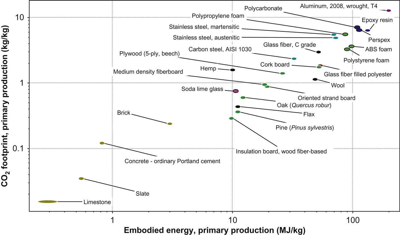
The environmental credentials of these materials, based on primary production of 1 kg of material, are plotted in Fig. 7.2. High-density natural building materials such as slate and limestone perform well, but low-density natural materials including wood, natural fibers, and wool are superior to metal alloys, polymers, polymer foams, and composite materials.
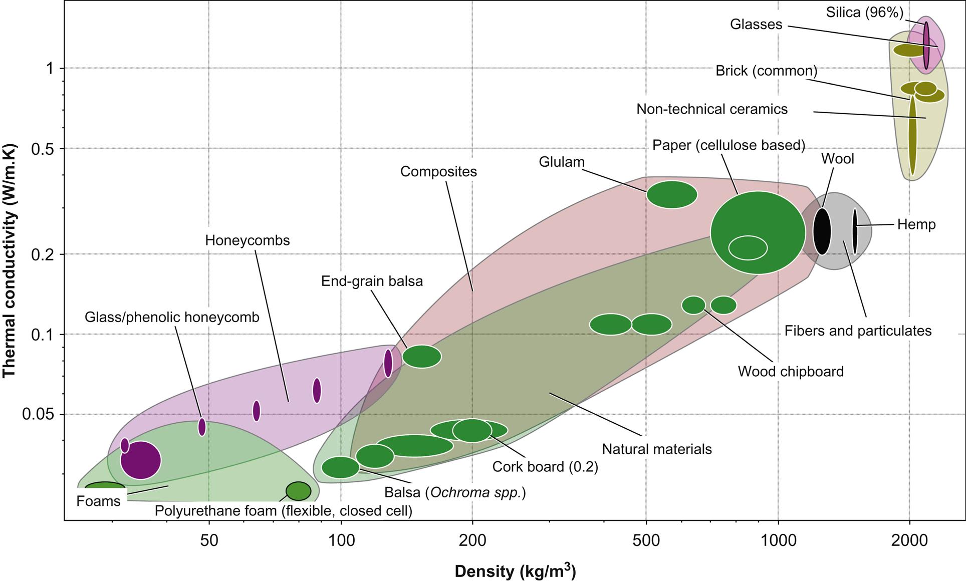
Thermal properties of building materials and their compressive strengths are compared in Fig. 7.3. Cork board, synthetic foams, and wood possess low values of thermal conductivity expected of insulation materials but there is considerable variation in compressive strength which may be an issue in construction. Overall, Figs. 7.1–7.3 demonstrate the complexity of materials selection but also show the advantages derived from the selection of natural materials.

The green materials under investigation in the ECO-SEE program include lime, clay, hemp fiber and shiv, straw, hemp–lime composites, wood fiber board, cellulose fiber, and sheep’s wool, which are combined together to form green composite structural panels. The properties and applications of natural limes, clays, hemp shiv, and straw are reviewed in the following sections and the application of composite materials made from these materials in construction is described. The application of PCs to these materials to neutralize VOCs and the negative social impact of poor IAQ are also discussed.
7.2 Green matrix materials
Clays, quarried or mined from a pit, and lime binders, produced from limestone and chalk, are available in abundance in the earth’s crust and are key green composite materials for construction.
7.2.1 Lime
Lime binders have been used in construction for over 6000 years and are manufactured by heating calcium carbonate to approximately 900°C (Allen et al., 2003). Limestone, chalk, or in coastal regions shellfish shells, are normally used as the source. Upon heating, calcium carbonate dissociates to calcium oxide and carbon dioxide according to Equation 7.1. The calcium oxide is then slaked by mixing with water to form calcium hydroxide (Equation 7.2). This process liberates heat and produces a dry hydrate unless an excess of water is added in which case a lime putty is formed (Margalha et al., 2013).
(7.1)
(7.2)
Limes consisting of mostly calcium hydroxide set entirely through carbonation according to Equation 7.3.
(7.3)
The equations above can be represented by the lime cycle visualized in Fig. 7.4.

In practice the carbon dioxide forms carbonic acid in the presence of water, which subsequently reacts with calcium ions forming carbonate. It is noteworthy that relative humidity and moisture content are important factors which determine the rate of carbonation, and thus hardening (El-Turki et al., 2007, 2010, Ball et al., 2011). Carbonation of a mortar normally occurs over a period of months or years.
Many natural limestones often contain impurities, which include among others the elements silicon, aluminum, and iron. During the calcination process a reaction occurs with oxides of these elements forming hydraulic phases. The most common of these phases in natural hydraulic limes is dicalcium silicate (C2S). In the presence of water this phase reacts according to Equation 7.4 forming calcium–silicate–hydrate (C–S–H).
(7.4)
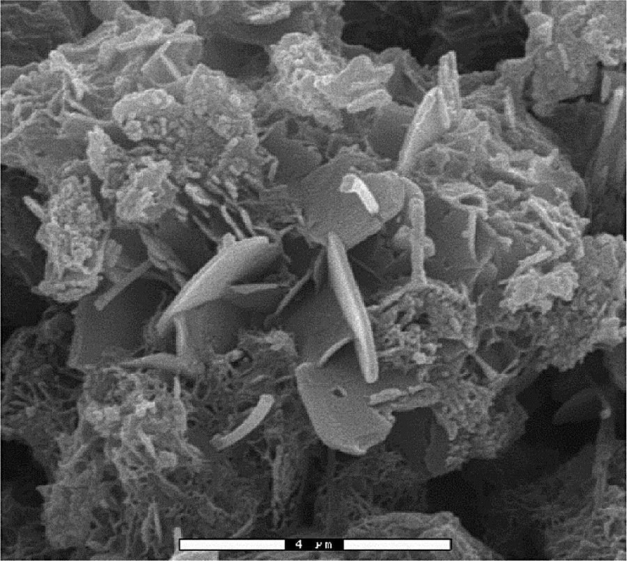
Fig. 7.5 shows the microstructure of an NHL5 lime mortar revealing hexagonal calcium hydroxide crystals and silicate regions identified as networks of high aspect ratio silicate needles.
Compared to carbonation this reaction is rapid, occurring over days or weeks, and provides an initial strength to the lime. Hydraulic limes are therefore used in applications where initial strength development is desirable (Ball et al., 2009). The strength of a lime binder can also be increased through the addition of a pozzolan such as volcanic ash (naturally occurring), ground granulated blast furnace slag (manmade), waste glass (Edwards et al., 2007), or clinkers made from waste materials (Raupp-Pereira et al., 2008) or in some cases cement.
Lime binders are commonly mixed with water and an aggregate to form a mortar, plaster, or render. These have numerous applications in the construction industry and are particularly appropriate in heritage applications and in combination with natural materials.
Compared to cement mortars, lime mortars have a lower-density and higher vapor permeability, making them particularly suitable for use in combination with organic fillers or fibers such as reeds, hemp, flax, and wood. During initial drying or following flooding or heavy rainfall the evaporation of water from the surface is promoted, thus reducing the risk of biological attack of organic materials within or covered by the lime matrix.
Lime mortars also have lower compressive and flexural strengths compared to equivalent materials containing a cement-based binder. Under deformation microcracks form which reduce stress concentrations and the risk of damage to masonry units (Ball et al., 2007). From a design perspective this may allow features such as thermal expansion joints to be omitted. In the case of a fiber composite, flexural and tensile properties will be improved as these cracks will be bridged. Over an extended period of time strength may be restored through autogenous healing. In the case of a lime which is not fully carbonated the presence of a crack will provide a channel through which carbon dioxide and water vapor can diffuse. Calcium hydroxide exposed on the interior surfaces of the crack will then carbonate, closing the crack and restoring strength.
Pollutant gases may also diffuse through the porous structure of lime and in the presence of sulfur dioxide lime-based building materials will react forming calcium sulfate, and where nitrogen oxides are present this process may be accelerated. The acids formed by these gases can attack organic materials suggesting that a lime matrix could act sacrificially, delaying the degradation of an organic filler. VOCs present in the indoor atmosphere may adsorb onto the surfaces of both an organic filler and lime matrix (Da Silva et al., 2016). Materials containing molecules with negative/positive charges, such as the hydroxyl groups present on the surface of lime, will promote adsorption of VOCs. The relatively high surface areas of organic fillers can also promote adsorption.
7.2.2 Clay
The use of clay as a matrix material is typically considered within the engineering of soil or earth constructions. This historic and vernacular construction technique is inherently a composite construction being an assemblage of discrete particles with a mineral composition. Traditionally this construction utilizes the binding properties of clay minerals to achieve desirable mechanical properties, but recent research has demonstrated their importance for indoor environment quality regulation.
Definitions of “clay” and of “clay mineral” vary between disciplines and are often interchanged. The plasticity and binding properties associated with clay soils are due to the presence of clay minerals, chemically defined as hydrous aluminum phyllosilicates (Fig. 7.6), whereas the term clay may only refer to the particle size. While there is a clear physical and chemical distinction between the two, as summarized by Bergaya et al. (2006), there is significant overlap that has led to their interchangeable use.

The binding mechanism of soils is due to capillary suction of water bound between the particles. Phyllosilicate minerals are particularly effective due to their large specific surface area and surface charges (Giese and Oss, 2002). The structure creates several different types of surfaces, including the external planar surfaces, edge surfaces, as well as internal interlayer surfaces. These surfaces can be easily modified through adsorption, ion exchange, or grafting.
Optimum mix design will depend on the application, but would typically incorporate a range of particulate sizes. For plaster applications, silts and sands would be included with larger cobbles incorporated into structural applications. The clay composite will have specific physical and chemical properties that give defined mechanical, hygrothermal, and IAQ properties and properties specific as a matrix material. As a matrix material within a larger composite, typical properties considered are plasticity, shrinkage, and durability that will affect the compatibility of the clay with any other additions or aggregates.
7.3 Green fibers
In this section the structure of two green fibrous materials, hemp shiv and straw, which are commonly employed in green construction, is described. Hemp shiv particles are combined with lime or clay to form a coarse composite with excellent hygrothermal and insulating properties whilst straw bales are faced with a breathable lime render to form modular units (Section 7.7).
7.3.1 Hemp shiv
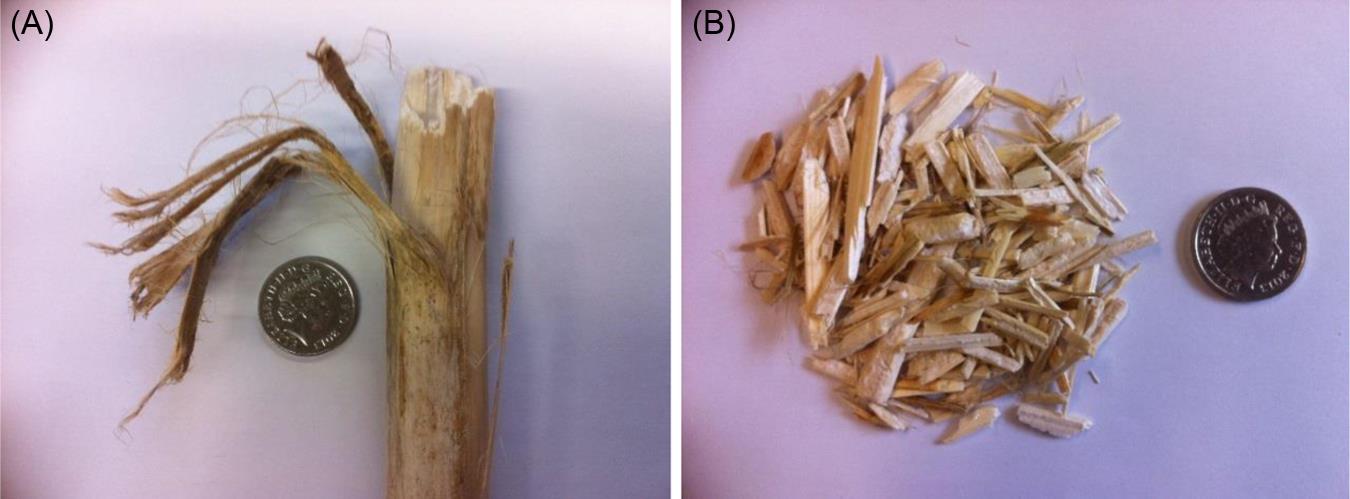
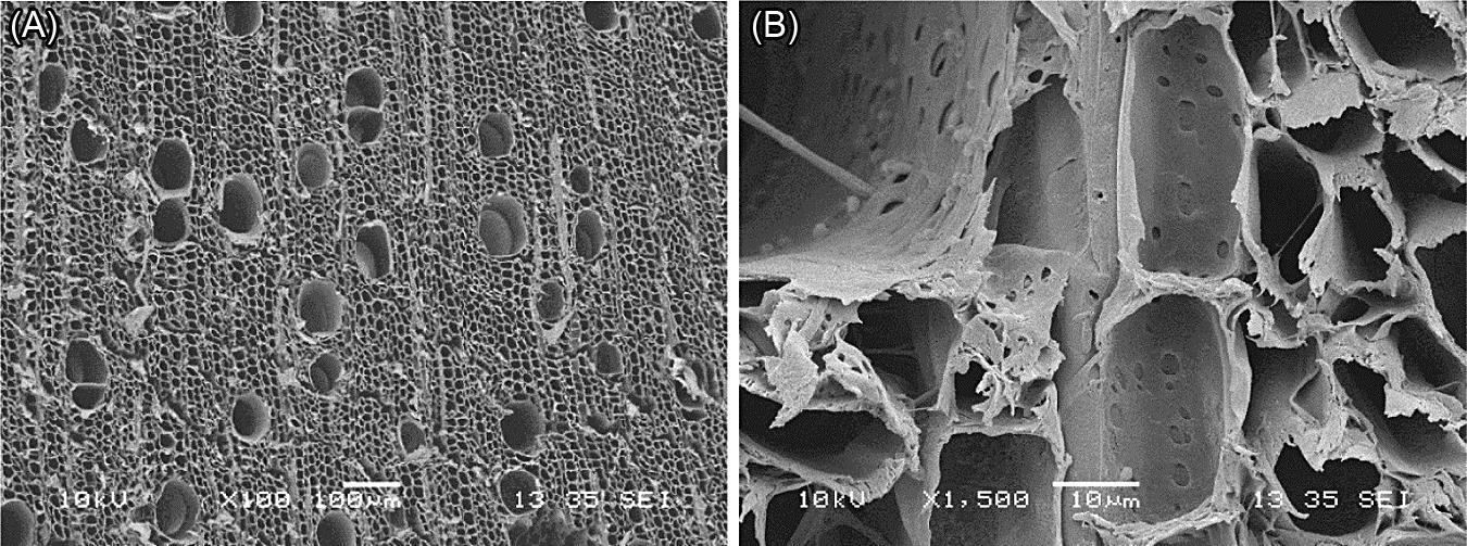
Hemp (Cannabis sativa) is a tall leafy plant which has been used for centuries for the manufacture of clothing, rope, and sails. It grows in temperate climates in Western and Eastern Europe. In recent years the mechanical fibers (Fig. 7.7A) which lie on the surface of the hemp stem have been incorporated into thermosetting resin matrices for the manufacture of automotive panels. In green composites for construction it is the woody core of the stem (Fig. 7.7B) which is employed as a particulate filler within lime and clay matrices.
The core material is fragmented into particles with aspect ratios (length to width) which lie typically between 2 and 10. The longitudinal cellular elements run along the major axis of the shiv particles. A cross-section through the hemp core (Fig. 7.8A) reveals a structure very similar to that of a diffuse pore hardwood with the absence of annual rings as expected in an annual plant and with a density of approximately 350 kg/m3. The longitudinal cellular elements are small cells (10–20 µm across) and vessels (50–120 µm across). Bands of radial cells run from top to bottom of Fig. 7.8A and at a higher magnification two radial cellular elements are imaged at the center of Fig. 7.8B together with a vessel at the top left. Both the rays and the vessel contain pit openings which allow the diffusion of moisture through the hemp shiv and contribute to its excellent hygroscopic properties.
7.3.2 Straw
Straw is an annual crop which contains slightly less cellulose (~57 wt%) than wood. Wheat straw has traditionally been regarded as a byproduct used for animal bedding and fodder, as a fuel, and for thatching. In the form of bales, it has been employed as a construction material for straw-bale houses with an external natural render such as lime or clay. It may also be used in short lengths as a reinforcement for concrete and clay and clay–straw mixtures are known as the basis for cob buildings.
Straw has a dense outer layer, the cellulose-rich epidermis (Fig. 7.9A and B), which has a thin layer of silica at its exterior surface. A ring of vascular bundles, containing the phloem, and meta-xylem vessels, is located adjacent to the epidermis in the softer lower-density cellular ground tissue. Moisture and nutrients are transported along the straw stem via the vascular bundles. White and Ansell (1983) measured the Young’s modulus (9.3±1.7 GPa) and the tensile strength (43.1±5.6 MPa) of the epidermis and these values are close to those of softwood (average values±standard deviation).
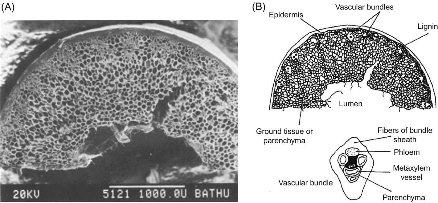
Straw stalks are comprised of longitudinal sections joined by bulbous nodes. In green construction straw is utilized in the form of conventional bales compressed into frames and faced with a clay, lime, or hemp–lime render to form a composite structure. The render binds to the friable straw structure and provides a breathable, hygroscopic internal and external membrane which is weather-proof.
7.4 Examples of construction with green composites
The use of green composites in construction has its roots in the self-build sector, and as a result construction techniques have tended to be labor-intensive and subject to poor quality control. For these materials to be adopted on an industrialized scale, more robust, economical and quality-assured techniques needed to be developed. Two such burgeoning techniques are modular construction and spray application.
7.4.1 Modular construction with green composites
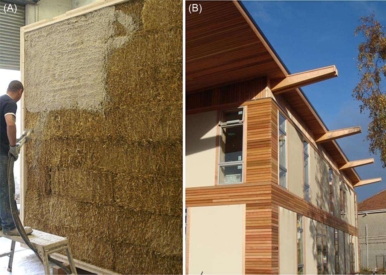
The two most commonly used biomaterials used in modular construction are straw and hemp. Fig. 7.10 shows the use of prefabricated structural straw-bale panels (ModCell) used to construct an arts center in Bristol (UK). The panels are typically 3×3.2×0.48 m3 with a structural timber frame infilled with straw bales, and a 30-mm breathable lime render applied to the surface of the straw (Fig. 7.10A). They are assembled in “flying factories” close to the construction site, to minimize the impact of transportation. The panels are rapidly assembled on site in order to produce a weather-tight envelope within a matter of days (Fig. 7.10B). Hemp–lime/hemp or wood fiber composite panels are also manufactured in the UK (HempCell) and have been used to construct houses to PassivHaus levels of performance.
7.4.2 Hemp–lime composite structures
Hemp–lime (Fig. 7.11A) is a building material often referred to as Hemcrete or Lime–Hemp (Shea et al., 2012).
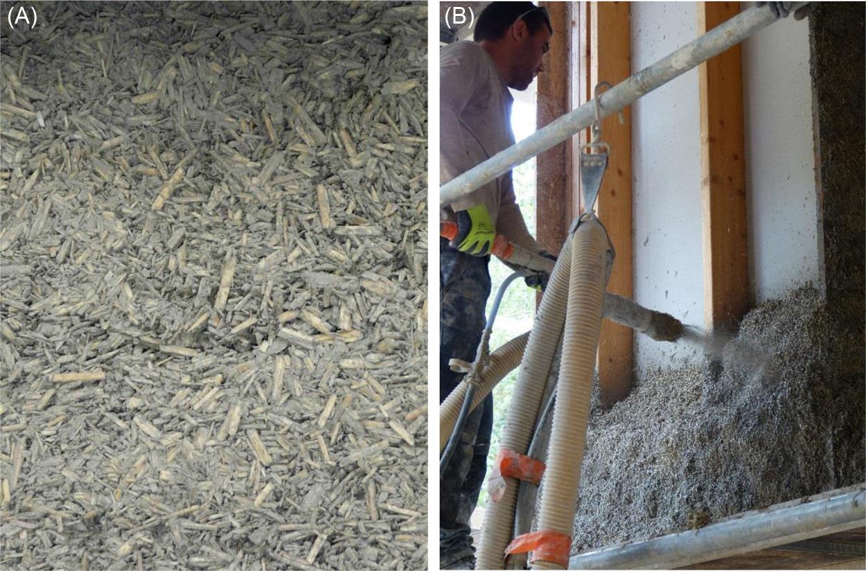
The material was originally developed as a replacement for wattle and daub infill in timber frame buildings in France, where the term used is Chaux–Chanvre. It is made by mixing the chopped woody core of the stalks of the hemp plant (Cannabis sativa), known as the “shiv,” with a binder made from air lime with pozzolanic, cementitious, or hydraulic lime additions, and in some cases small amounts of other additives such as surfactants (Fig. 7.11A). The material is used to form building envelopes by casting between, or spraying against, temporary or permanent shuttering in situ (Fig. 7.11B), or by prefabrication of building blocks or panels. Typically walls are constructed to be 300 mm in thickness giving U-values of the order of 0.15 W/m2 K. Both in situ casting and spraying techniques produce thermally efficient buildings because they produce continuous envelopes which make for airtight envelopes which have very few thermal bridges. The external surface of the hemp–lime is typically rendered with a breathable lime render. Hemp shiv can also be used as an insulating element in lime renders.
The fibers that surround the woody core of the hemp stalk, historically used for rope, clothing, and paper are now used to make low-carbon thermal insulation with thermal conductivity levels of around 0.044 W/m K, which is comparable with glass fiber insulation. These can be combined with hemp–lime in composite prefabricated panels to produce building envelopes with U-values of the order of 0.11 W m2 K in walls of 300 mm thickness.
7.5 Thermal conductivity of green building insulation materials
7.5.1 Introduction
Building insulation materials are manifest in a variety of forms but most commonly as loose fill, fibrous batts, or rigid foamed boards. The key characteristic of any thermal insulation material is its ability to reduce heat transfer and such characteristics are derived from its chemical nature and/or its physical structure. The fundamental transport property of insulation material is its thermal conductivity, W/m.K, symbol λ or sometimes k. Numerical limits defining insulation performance are application-specific, i.e., there is no single value across all applications below which a material is defined as thermally insulating. However, in building construction applications a figure of approximately 0.07 W/m K can be regarded as an upper limit. In some regions, or for inhomogeneous materials, it is common to specify material thermal performance in the form of a thermal resistance, R-value (m2 K/W), which relates to a specified thickness, d, of material, such that R=d/λ. In practice, measured thermal conductivity, also known as apparent or effective thermal conductivity, is influenced by several modes of heat transfer including radiation and convection, and thus is not solely heat conduction. Additionally, orientation, density, temperature, and moisture content have an influence on the in-service thermal performance of thermal insulation materials.
Historically, databases and textbooks of approximate thermal conductivity values of typical construction materials have been a popular source of information for practitioners and modelers engaged in the estimation of building energy performance. However, development of novel materials, biocomposite materials, and insulation products such as aerogels, hemp–lime, and vacuum insulated panels combined, in many regions, with an increasing need for more detailed and precise simulation modeling of building energy performance has necessitated increased laboratory testing of building insulation materials and systems.
Methods for the measurement of thermal conductivity of building insulation materials fall into two categories, namely steady-state or transient. Steady-state one-dimensional methods are most common in the testing of building materials and within this group there are two basic types of measurement which are referred to as absolute or by comparison. A widely used absolute method is that of the guarded hot plate, whilst the heat flow meter represents a widely used comparison method. In both test apparatus a test specimen is inserted between hot and cold plates, typically held at 20°C and 0°C. A constant heat flux is established at a steady temperature gradient and the thermal conductivity is determined by the heat flux, the mean temperature difference between the sample surfaces, and the dimensions of the sample. The absolute method determines the power through a specimen directly from the electrical power input measurements. The heat flow meter compares measurements to a reference standard insulation material of a known thermal conductivity. The absolute method is considered to be the most accurate method (Salmon, 2001) although the heat flow meter method has for many years been accepted worldwide as the prime secondary method (Shirtliffe and Tye, 1985). Whilst steady-state methods are the most widely used for material certification, devices employing dynamic methods are now commercially available and offer a major advantage in terms of a much shorter test duration. Dynamic methods are typically indirect and, based on the response to periodic or pulse-type thermal excitation, measure the thermal diffusivity of the test specimen.
Fig. 7.12 presents thermal conductivity against density for a range of building materials (CES EduPack, 2016). Thermal conductivity increases with density as porosity decreases. However, for many insulation materials at low densities thermal conductivity increases as density decreases due to the effect of long-wave radiant exchange inside the pores (Domínguez-Muñoz et al., 2010). Natural fiber and other insulation materials exhibit this “fish-hook” measured conductivity for varying density.
7.5.2 Aerogel and bio-based composites
In recent years there has been an increasing interest in the research, development, and use of highly insulating materials, such as aerogels, due to their very high thermal performance, λ=0.012–0.020 W/m K, (Aegerter et al., 2011). In addition, there has been similarly increased attention paid to the benefits of bio-based insulation materials, such as hemp or wood fiber, primarily for their low environmental impact and moisture-buffering potential. Research conducted as part of the ISOBIO project (http://isobioproject.com/) has led to the development of a composite rigid insulation material using hemp shiv with a sol–gel process and an integrated surface layer of hemp fiber for which preliminary heat flow meter tests indicate thermal conductivity values approximately 40% lower (<0.04 W/m K) than hemp shiv formed with conventional lime-based binder.
The use of aerogels in the quantities required for building projects remains prohibitively expensive, whereas bio-based insulation materials, such as cellulose materials, made from recycled paper products, and natural fiber insulation (NFI) materials, which include sheep’s wool, straw, and hemp, have the benefits of relatively low cost, moisture-buffering capabilities, and thermal performance similar to that of more conventional alternatives.
7.5.3 Cellulose
Cellulose insulation made from recycled paper products, typically scraps from paper mills or recycled newspapers, provides a high-performance insulation material of low environmental impact. In common with other loose fill insulation materials, cellulose flakes are often blown in to a building cavity or void and can, therefore, be applied to both retrofit and to new building constructions. In retrofit applications, the use of cellulose flakes in cavity walls has led to reductions of winter heating costs of between 60% and 70% (http://www.nesocell.com/). Loose fill materials are prone to slump and this settlement can lead to air gaps forming, which significantly reduces the overall thermal resistance of the building element, leading to increased heat loss and potential occupant discomfort. To avoid settlement of loose fill material within a cavity the density at which the material is installed must be controlled and, for cellulose flakes, this is typically required to be between 45 kg/m3 and 65 kg/m3. At typical densities the thermal conductivity of cellulose insulation is approximately 0.04 W/m K (Jelle, 2011), which is comparable to mineral wool and similar fibrous insulation materials.
7.5.4 Sheep’s wool
The hygroscopic behavior of sheep’s wool is widely reported (Tuzcu, 2007; Zach et al., 2012). Wool fibers have the capacity to absorb moisture up to approximately 33–35% of their dry mass (Tuzcu, 2007; Cuce et al., 2014). In timber-framed construction, this hygroscopic ability is potentially beneficial for the preservation of timber elements. Density for the installed product is typically between 15 kg/m3 and 25 kg/m3 (Tuzcu, 2007; Cuce et al., 2014) and thermal conductivity 0.033–0.042 W/m K. The thermal conductivity of sheep’s wool has been shown to be largely insensitive to changes in moisture content up to around 25%. Furthermore, sheep’s wool isotherm data indicate that a 25% moisture content equates to equilibrium with an environment with >90% relative humidity (RH) (Zach et al., 2012). In common with hemp and wood fiber, sheep’s wool is often formed into batts, which, whilst convenient for installation, can also suffer similar problems to loose fill material with respect to slump and also air gaps due to poor installation. Research has shown that gaps of only a few millimeters around the edges of wall insulation can significantly reduce the overall thermal resistance of a building envelope (Cox-Smith, 2010).
7.5.5 Hemp–lime
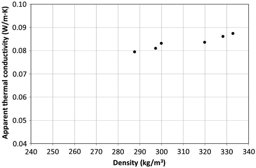
Hemp–lime is a building material originally developed as a replacement for wattle and daub infill in timber frame buildings in France, where the term used is Chaux–Chanvre. It is made by mixing the chopped woody core of the stalks of the hemp plant (Cannabis sativa), known as the shiv, with a binder made from air lime with pozzolanic, cementitious, or hydraulic lime additions.
The material is used to form building envelopes by casting between, or spraying against, temporary or permanent shuttering in situ, or by prefabrication of building blocks or panels. Fig. 7.13 presents thermal conductivity against density for six hemp–lime test specimens (Shea et al., 2012). The use of a lime binder to form a solid material, often referred to in the UK as hempcrete, increases its overall thermal conductivity, although the material presents a good balance between low mass and heat storage capacity compared with classical insulation materials (Tran Le et al., 2010).
7.6 Vapor sorption and desorption for climate control—moisture-buffering
The internal relative humidity is a significant factor of indoor environment quality, influencing occupant health and wellbeing. The optimum levels of relative humidity are between 40% and 60%, with levels outside of this optimum range associated with discomfort, health risks, and degradation of a building (Sterling et al., 1985). Relative humidity levels above 60% result in the growth of microorganisms, whilst relative humidity levels below 40% are associated with discomfort and respiratory conditions (Fang et al., 1998; Toftum et al., 1998; Lucas et al., 2002). While the relative humidity can be regulated through a suitably designed air conditioning strategy, exposed materials as part of a building's fabric are also able to contribute to the relative humidity regulation (Janssen and Roels, 2009; Osanyintola and Simonson, 2006).
Comparable to thermal mass, many materials exhibit a moisture-buffering effect, which through mass transfer of water vapor is able to passively regulate the indoor relative humidity. This buffering effect is provided by hygric mass, referred to as the vapor, or moisture, absorption capacity of a material, capable of buffering humidity variations inside a room. This is observed through sorption isotherms as seen in Fig. 7.14.
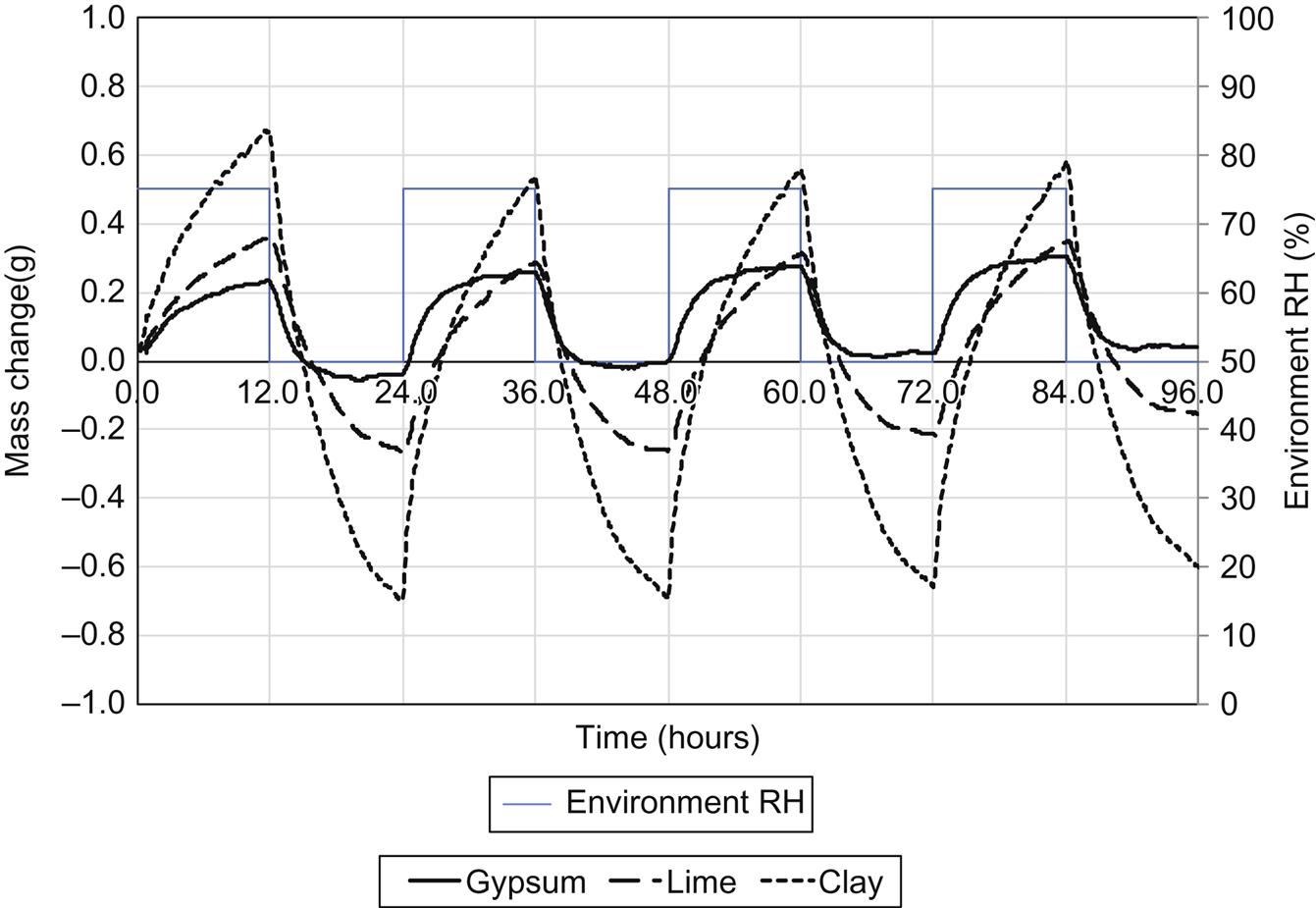
Clay- and lime-based plasters have been shown to passively interact with the internal environment compared to conventional materials (Koronthalyova and Matiasovsky, 2005). Padfield (1998) showed experimentally that clay has a greater capacity to buffer humidity than lime-based plasters. Hemp–lime materials have been increasingly investigated with respect to their potential to buffer humidity as well as to provide thermal insulation (Barclay et al., 2014). The moisture-buffering properties of composites based on lime and clay matrix materials have been shown to benefit from the addition of bio-based fibers (Maskell et al., 2015; Thomson et al., 2015).
7.7 Photocatalytic coatings for control of VOCs and greenhouse gases
PCs may be applied to surfaces as thin films or incorporated into binders such as lime mortars. The principles of photocatalytic action and the ability of PCs to neutralize VOCs and GHGs is described in this section. The evaluation of PCs for improving the quality of the indoor air environment is a key feature of the ECO-SEE program.
7.7.1 Photocatalytic coatings
A photocatalyst accelerates a reaction under light without undergoing any changes itself. The photocatalytic activity of ZnO was studied in the 1930s and since then there has been increasing research of photocatalytic materials in many countries including Germany, the USA, and Japan (Park, 2009). Fujishima and Honda (1972) from the University of Tokyo discovered the photocatalytic properties of TiO2 and published a paper in the journal Nature describing the possibility of converting light energy into chemical energy.
Although there are various kinds of photocatalyst, TiO2 is widely considered as one of the most suitable substances for commercialization. TiO2 is relatively cheap, stable, and has high photocatalytic efficiency. Moreover, TiO2 is nontoxic to human health and has been used as a white pigment since ancient times.
Scientific studies of TiO2 under sunlight began in the early 20th century. In 1921, Renz published a paper on the oxidation of organic compounds by TiO2 (Park and Song, 2001). In 1938, the formation of active oxygen on the surface of TiO2 was reported with no changes in the TiO2 under UV exposure (Goodeve and Kitchener, 1938). The photocatalytic properties of TiO2 were introduced through studies by Mashio describing the autoxidation by TiO2 as a photocatalyst around 1956 (Kato and Mashio, 1956). TiO2 powder was mixed with organic solvents and the autoxidation of the solvents with H2O2 formation under the UV observed. The anatase crystalline form of TiO2 was found to be most efficient at autoxidation.
Photocatalytic materials are semiconductors. Various types of TiO2-based PCs exist with different efficiencies, however they all share the same reaction principle which occurs on the surface of the semiconductor (Nuño et al. 2015a). An electron–hole pair is generated by light as shown in Fig. 7.15.
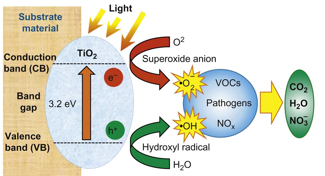
When TiO2 is irradiated by ultraviolet light a photon of higher energy than the 3.2 eV band gap is absorbed, and electrons and positive holes move toward the surface. These species react with O2 and H2O forming super oxide (O2−) and hydroxyl (OH) radicals. These species are highly reactive particularly in the presence of organic molecules (Park and Song, 2001).
Holes and electrons can react with species adsorbed (ads) onto the surface:

Hence GHGs such as oxides of nitrogen and carbon, methane, and VOCs can be chemically broken down and neutralized.
7.7.2 The antibacterial effect of photocatalytic coatings
The oxidizing species generated by a photocatalyst under light can react with the organic molecules of microorganisms. Macromolecules, such as lipids or proteins, are structural components of living cells. Thus, photocatalytic processes have a biocidal activity. Reactive species, such as peroxides or hydroxyl radicals, attack lipid bilayer membrane proteins, creating holes in the cell wall. These holes can be directly responsible for the death of the cell. Alternatively, if radicals enter into the cell, they will oxidize Fe2+ to Fe3+ and OH·. The OH· radical has the ability to oxidize DNA and proteins, destroying the cell (Bak et al., 2011; Oka et al., 2008; Dunnill et al., 2009; Zhang et al. 2011). In practical applications however the application of pure TiO2 photocatalyst materials on the inside of buildings has been of limited success due to the low (several hundred nW/cm2) intensity of UV light. Recent advances in TiO2 photocatalytic technology by the addition of silver or copper have led to improvements allowing reaction under fluorescent light. The survival rates of copper-resistant Escherichia coli cells on a Cu/TiO2 films under various UV conditions were observed by demonstrating the effectiveness of the coating even under a relatively low light intensity where the copper ions destroyed the cells' cytoplasmic membrane (Sunada et al., 2003).
7.7.3 Commercialization of TiO2
The hydrophilic property of TiO2 was discovered in the mid-1990s after which a number of antifogging and water-repellent surfaces for glass were developed which are available on the market. However, the commercialization of photocatalytic materials for the decomposition of pollutants in cities has been hindered by low efficiency.
Decomposition of substances such as benzene, VOCs, and NOx by TiO2 PCs have been studied in detail (Park and Song, 2001; Matsuda and Hatano, 2005). More recently nano-sized TiO2 particles and TiO2 particles containing metal-doped structures have received greater attention. Current examples of the application of TiO2 in construction include the Church for the Jubilee in Rome and the application of HYDROTECT color coat ECO-EX, a photocatalytic painting coat manufactured by TOTO Ltd., to the exterior wall of the Toyota Tsutsumi plant.
In many applications where vapor permeability is an important factor an appropriate binder must be used to attach the TiO2 onto the surface. The use of lime is receiving interest for this application (Nuño et al. 2015b; Karatasios et al., 2010). TiO2 was successfully combined with lime to produce new mortar mixtures for conservation purposes. This binary mixture was found to carbonate considerably faster than a standard lime. The increase was attributed to a high carbon dioxide concentration, resulting from the photocatalysis (photooxidation) of organic pollutants.
Producing an efficient PC introduces a number of important technical challenges. Fig. 7.16 provides a two-dimensional illustration of three PCs (A), (B), and (C). In coating (A) the particles are bonded to the surface of the substrate and exposed to light. This is an ideal situation in terms of efficiency of photocatalytic particle use as all the particles are active. However if the surface is abraded the particles will be lost and the surface will no longer be photocatalytic. Depending on the nature of the substrate, for instance in the case of an organic substrate material, over time the bond attaching the particle may become degraded, also leading to detachment. Coating (B) contains particles on the surface but also beneath. The particles at the surface will perform as described for surface (A), however those beneath the surface will only become active if the substrate material is abraded exposing them. This is a potential advantage, however the overall cost will be higher. In coating (C) the substrate is porous, allowing light to travel into the near surface and subsequently activate subsurface particles. This may be the case for materials such as porous lime renders. Within the ECO-SEE program Giampiccolo et al. (2016) presented results for photocatalytic tests on lime mortars and polymer coatings containing titanium dioxide anatase particles where a strong photocatalytic response was observed.

7.8 Social impact of greening the built environment
The current global insulation market for both new-build and renovation is worth US$ 31.3 billion globally per annum and is growing annually at 6.3%. In Europe the market for natural insulation materials including wool, cellulose, and hemp has grown to 2%. In Germany this figure has reached 10% and it is likely to rise to between 5% and 10% in other EU countries including the UK. Green insulation will result in improved levels of comfort, safety, health, and durability, with the bonus of good recyclability or reuse.
Natural plasters, such as clay and lime, offer improved permeability and hygroscopic control of the indoor environment compared to traditional gypsum-based plasters. The market for indoor plasters in Europe is valued at €25 billion per annum. It is expected that the natural plaster market will achieve 2–4% penetration in the next 10 years. Hygrothermal and moisture-buffering materials reduce ambient relative humidity levels and natural materials offer increased buffering speed and the potential to control internal relative humidity to within the range of 40–60% for at least 95% of the time. Such control has a positive impact on the health of occupants and a further bonus is the 15–20% reduction in embodied energy related to natural clays and plasters.
Pollution is estimated to be responsible for 40,000 deaths per year at a cost of £20 bn. A report published in 2016 by the Royal College of Physicians and the Royal College of Pediatrics and Child Health, examines the impact of indoor pollution and its link to harming the health and intelligence of children. PCs applied to panel products lining the inside of buildings offer new functionality where airtight rooms in low-carbon building projects suffer from poor air circulation and there is a need to neutralize GHGs and VOCs, including formaldehyde. VOCs are continuously produced by emissions from sources which include smoking, faulty boilers, gas cookers, and heaters, as well as irritant chemicals from new furniture, air fresheners, and household cleaning products. If PCs are applied to wall panels in conjunction with natural lime and clay finishes there is the additional bonus of combining green materials with self-perpetuating, light-activated, photochemical action to degrade contaminants. PCs are also known to suppress microbial contamination in the form of the growth of molds and the requirement to use toxic biocides is eliminated. These innovative coatings have a significant social impact on the wellbeing of occupants.
Estimates of the embodied energy of insulation products indicate that NFI lies in the range 8–20 MJ/kg compared to 16–28 MJ/kg for mineral fiber insulation and 70+MJ/kg for polyurethane foam. Hence the low embodied energy of natural materials and green composites reduces energy consumption and associated pollution. The activity of building is the biggest contributor to climate change and the increased use of natural building materials in the form of green composites will have a high positive impact on reducing GHG emissions with clear benefits for society.
Acknowledgment
The authors received funding from the EU’s Seventh Framework Programme for Research, Technological Development under grant agreement number 609234.