Chapter 3
Green Multi-homing Approach
The wireless communication medium has become a heterogeneous environment with overlapped coverages due to the coexistence of different cells (macro, micro, pico and femto), networks (cellular networks, WLANs and WMANs) and technologies (RF, VLC and D2D communications). In such a networking environment, MTs are equipped with multiple radio interfaces. Through multi-homing capability, an MT can maintain multiple simultaneous associations with different networks. Besides improving the achieved data rate through bandwidth aggregation, the heterogeneous wireless medium together with the multi-homing service can boost energy efficiency of network operators and mobile users. This is mainly due to the vast diversity in fading channels and propagation losses among MTs and BSs, available resources and operating frequency bands of different networks. This chapter mainly focuses on promoting energy efficiency in wireless networks through multi-homing resource allocation, exploiting network cooperation and integrating different and new network technologies such as RF and VLC. In such a network setting, a joint bandwidth and power allocation approach, for uplink and downlink communications, can promote energy savings for both mobile users and network operators. In this chapter, we first present the heterogeneous wireless communication medium, then discuss the potentials of multi-homing approach in green communications and focus on several challenging issues pertaining to the design and implementation of the green multi-homing approach.
3.1 Heterogeneous Wireless Medium
At present, the wireless communication medium is a heterogeneous environment with overlapped coverage from different networks (cellular networks, WLANs and WMANs), cells (macro, micro, pico and femto) and technologies (RF, VLC and D2D communications) [1]. Despite the fierce competition in the wireless service market, the aforementioned wireless networks, cells and technologies will continue to coexist due to their complementary service capabilities. For instance, while the IEEE 802.11 WLANs can support high data rate services in hot spot areas, the cellular networks and the IEEE 802.16 WMANs can provide broadband wireless access over long distances and serve as a backbone for hot spots [12]. The basic components of such a heterogeneous wireless communication network are the wireless networks, MTs and a core Internet protocol (IP)-based network [3], as illustrated in Figure 3.1. The wireless networks allocate radio resources to MTs to equip them with connectivity via the IP-based core network. Next, we describe the heterogeneous wireless network components, including the wireless networks and MTs with emphasis on the available radio resources and propagation attenuation [126].

Figure 3.1 Illustration of a heterogeneous wireless network [126]
3.1.1 Wireless Networks
The heterogeneous wireless medium is composed of a set ![]() of wireless networks, which can have different access technologies, such as the fourth-generation (4G) cellular networks, WLANs, VLC and WMANs, as illustrated in Figure 3.1. While 4G cellular networks, WLANs and WMANs rely on different RF access technologies, VLC relies on visible light for communications. Particularly, in VLC networks, communications take place by modulating the intensity of light in light-emitting diodes (LEDs) in such a way that it is not observed by the human eyes. Consequently, the illumination energy that is consumed for lighting is also used for communications. More details about VLC networks, the challenging issues in integrating VLC with RF networks and radio resource allocation in an integrated VLC and RF network for green communications are provided in Chapter 6. Chapters 3 through 5 mainly focus on the integration of RF networks for green communications. The cellular networks in
of wireless networks, which can have different access technologies, such as the fourth-generation (4G) cellular networks, WLANs, VLC and WMANs, as illustrated in Figure 3.1. While 4G cellular networks, WLANs and WMANs rely on different RF access technologies, VLC relies on visible light for communications. Particularly, in VLC networks, communications take place by modulating the intensity of light in light-emitting diodes (LEDs) in such a way that it is not observed by the human eyes. Consequently, the illumination energy that is consumed for lighting is also used for communications. More details about VLC networks, the challenging issues in integrating VLC with RF networks and radio resource allocation in an integrated VLC and RF network for green communications are provided in Chapter 6. Chapters 3 through 5 mainly focus on the integration of RF networks for green communications. The cellular networks in ![]() can have different cell sizes, for example macro, micro, pico and femto cells. In such a networking environment, different networks are assumed to be operated by different service providers. Also, different networks operate in different radio frequency bands. Every network has a set of BSs or access points (APs),
can have different cell sizes, for example macro, micro, pico and femto cells. In such a networking environment, different networks are assumed to be operated by different service providers. Also, different networks operate in different radio frequency bands. Every network has a set of BSs or access points (APs), ![]() for network
for network ![]() , to provide service coverage, radio resource management, user mobility management and access to the Internet.
, to provide service coverage, radio resource management, user mobility management and access to the Internet.
With overlapped coverage from the BSs/APs of different networks, different service areas can be distinguished. The set of service areas is denoted as ![]() . Each service area,
. Each service area, ![]() , is covered by a unique subset of BSs/APs of various networks. For instance, as shown in Figure 3.1, service area 2 is covered by the cellular network and the WMAN, while service area 3 is covered by all the three networks.
, is covered by a unique subset of BSs/APs of various networks. For instance, as shown in Figure 3.1, service area 2 is covered by the cellular network and the WMAN, while service area 3 is covered by all the three networks.
Network ![]() (
(![]() ) BS/AP
) BS/AP ![]() (
(![]() ) has a maximum available bandwidth of
) has a maximum available bandwidth of ![]() . A cooperative networking environment is considered, where the BSs/APs of different networks are connected through a backbone that enables them to exchange their signalling information.
. A cooperative networking environment is considered, where the BSs/APs of different networks are connected through a backbone that enables them to exchange their signalling information.
3.1.2 Mobile Terminals
The networking environment assumes a set ![]() of MTs. Network
of MTs. Network ![]() BS/AP
BS/AP ![]() has a subset of MTs
has a subset of MTs ![]() that lie in its coverage area. Two modes of communications can be distinguished for each MT. The first mode is based on the communication between MT
that lie in its coverage area. Two modes of communications can be distinguished for each MT. The first mode is based on the communication between MT ![]() with network
with network ![]() BS/AP
BS/AP ![]() . The second mode relies on direct communications among MTs in close proximity based on D2D communications. This part of the book (Chapters 3 through 6) mainly focuses on green communications among MTs and BSs/APs. More details about D2D communications and their application to green communications are provided in Chapters 9 and 10.
. The second mode relies on direct communications among MTs in close proximity based on D2D communications. This part of the book (Chapters 3 through 6) mainly focuses on green communications among MTs and BSs/APs. More details about D2D communications and their application to green communications are provided in Chapters 9 and 10.
Each MT is equipped with multiple radio interfaces, and assumes a multi-homing capability for multiple simultaneous associations with different networks. Hence, a given application of the MT, for example, data downloading/uploading or video streaming, can be served on the downlink/uplink using multiple networks. Such an infrastructure presents the following advantages [4]. First, using the multi-homing capability, the available resources at different networks can be aggregated to support bandwidth-hungry applications through multiple threads at the application layer. Second, multi-homing calls enable better mobility supports to ensure that at least one of the used radio interfaces will remain active during the call. Third, the multi-homing support can reduce the call-blocking rate and improve the system capacity.
Each MT ![]() has its own home network, but it can also get service from other available networks at its location, using the multi-homing capability. The subset of MTs
has its own home network, but it can also get service from other available networks at its location, using the multi-homing capability. The subset of MTs ![]() in the coverage area of network
in the coverage area of network ![]() BS/AP
BS/AP ![]() is divided into the subset
is divided into the subset ![]() of network subscribers whose home network is network
of network subscribers whose home network is network ![]() and the subset
and the subset ![]() of network users whose home network is not network
of network users whose home network is not network ![]() .
.
3.1.3 Radio Resources and Propagation Attenuation
Let ![]() (
(![]() ) denote the allocated bandwidth from network
) denote the allocated bandwidth from network ![]() BS/AP
BS/AP ![]() to MT
to MT ![]() on the uplink (downlink), where the allocated bandwidth is equal to 0 for
on the uplink (downlink), where the allocated bandwidth is equal to 0 for ![]() . Let
. Let ![]() (
(![]() ) denote the allocated transmission power for communication between MT
) denote the allocated transmission power for communication between MT ![]() and network
and network ![]() BS/AP
BS/AP ![]() on the uplink (downlink). In addition, let
on the uplink (downlink). In addition, let ![]() denote the circuit power that is required to keep the radio interface active for communication between MT
denote the circuit power that is required to keep the radio interface active for communication between MT ![]() and network
and network ![]() BS/AP
BS/AP ![]() , with
, with ![]() for
for ![]() . The maximum power is denoted by
. The maximum power is denoted by ![]() for MT
for MT ![]() , and by
, and by ![]() for network
for network ![]() BS/AP
BS/AP ![]() .
.
The channel power gain between MT ![]() and network
and network ![]() BS/AP
BS/AP ![]() on the uplink (downlink) is denoted by
on the uplink (downlink) is denoted by ![]() (
(![]() ), and it captures both the channel fast fading and path loss. Let the distance between MT
), and it captures both the channel fast fading and path loss. Let the distance between MT ![]() and network
and network ![]() BS/AP
BS/AP ![]() be
be ![]() and the path loss exponent be
and the path loss exponent be ![]() . Hence, the path loss between MT
. Hence, the path loss between MT ![]() and network
and network ![]() BS/AP
BS/AP ![]() is given by
is given by ![]() , where
, where ![]() and
and ![]() denotes the far-field distance of the transmitting antenna. The one-sided noise power spectral density is denoted by
denotes the far-field distance of the transmitting antenna. The one-sided noise power spectral density is denoted by ![]() .
.
3.2 Green Multi-homing Resource Allocation
In the literature, various energy-efficient (green) radio resource allocation schemes have been proposed to satisfy the mobile user-required QoS at reduced energy consumption. Two categories of solutions can be distinguished in the heterogeneous networking environment, for single-network access and multi-homing access, respectively, as discussed in Chapter 2. The single-network access radio resource allocation schemes do not fully exploit the available resources in the heterogeneous wireless medium, where an MT can communicate through multiple radio interfaces with different channel conditions and radio bandwidths to enhance the energy efficiency. In multi-homing access, an MT connects to all available BSs/APs of different networks, and radio resources are allocated to enhance energy efficiency in the networking environment.
In the literature, multi-homing energy-efficient (green) radio resource allocation mechanisms, for example, [33], mainly deal with how to optimally allocate uplink/downlink transmission power by adapting to different channel conditions and path losses among MTs and BSs/APs, given an allocated bandwidth. In addition to exploiting channel conditions and path losses from different BSs/APs in a heterogeneous wireless medium, other resources can be used to enhance energy efficiency, such as the available bandwidths and different operating frequency bands at different BSs/APs. Hence, the resulting energy efficiency can be further improved through a joint bandwidth and power allocation approach [126]. Different MTs can be allocated different amounts of bandwidths on the uplink (downlink), based on the MT (BS) maximum power and channel conditions, which will affect the associated transmission power allocation.
While the joint bandwidth and power allocation approaches have been investigated in the literature for OFDMA networks in terms of joint sub-carrier allocation and power control, the existing works are mainly limited to single-network access. As a result, the solutions proposed for OFDMA networks cannot be directly applied to the heterogeneous networking environment due to the following facts. First, in an OFDMA single-network access, the networking environment does not present different service areas with service coverage from unique BSs/APs. Second, in a heterogeneous wireless medium, the MT is located at different distances from the BSs/APs of different networks (and hence suffers from different path losses), which affects the resource allocation decision differently from the single-network access, where an MT is served by only one BS/AP. Third, in a single-network access, the resource allocation decision does not need coordination among BSs/APs of different networks, which is different from the heterogeneous networking environment. Hence, the heterogeneous networking settings have to be taken into consideration in developing a joint bandwidth and power allocation approach to maximize energy efficiency.
Consider an uplink communication scenario in a heterogeneous networking environment, as illustrated in Figure 3.2 via MTs 1 and 2. The MTs are located at different distances from the three BSs and experience different channel conditions. In addition, the three BSs have different available bandwidths. In this scenario, the MT with low battery energy and/or bad channel conditions (e.g. MT 1) can be allocated larger bandwidth by the BSs (BSs 1 and 2) than the MT with high available battery energy and/or better channel conditions (e.g. MT 2 which obtains its required bandwidth from BSs 2 and 3) to satisfy the required QoS of both MTs, via a multi-homing service. This in turn can reduce the energy consumption for the MT suffering from low available energy and/or bad channel conditions (MT 1), which leads to improved energy efficiency for the networking environment. The objective of resource allocation is to enhance the energy efficiency of the MTs, while satisfying their required QoS. In this context, the main factors affecting the resource allocation decision are the MT available energy and required QoS, and the available bandwidths at the BSs, together with the channel conditions.

Figure 3.2 Illustration of multi-homing uplink and downlink radio communications in a heterogeneous wireless medium [126]
Similarly, for a downlink communications scenario, as illustrated in Figure 3.2 using MTs 3 and 4, the BSs/APs can allocate their available bandwidths to MTs to increase the energy efficiency of the different networks. Unlike the uplink communications scenario, the main factors affecting the resource allocation decision include the BS/AP maximum transmission power in addition to their available bandwidths and MTs' required QoS, together with channel conditions.
The joint bandwidth and power allocation approach can be regarded as a cross-layer design since bandwidth is allocated at the network layer from the BSs/APs of different networks, while the transmission power (and circuit power for MTs) is allocated at the physical layer. Such a cross-layer design can implement opportunistic communication over the wireless links for a set of MTs with different channel conditions and available energy to enhance energy efficiency of the networking environment. This is possible through backward and forward information flows between the network and physical layers. Such a cross-layer design spans not only different layers but also different entities, that is, BSs/APs of different networks and MTs. Coordination is required among different layers and entities (MTs and networks on one side and different networks on the other side) in the joint bandwidth and power allocation approach. Different networks should coordinate their allocated resources (bandwidth in uplink and downlink and transmission power in the downlink) to maximize the energy efficiency. Hence, the joint bandwidth and power allocation approach represents a cross-layer design in a cooperative networking setting.
In such a networking environment, to develop an energy-efficient joint bandwidth and power allocation approach, several challenging issues need to be addressed, as discussed in the next section.
3.3 Challenging Issues
There are various technical challenges towards developing a joint bandwidth and power allocation approach. Further studies are required to deal with single-user versus multiuser systems, single-operator versus multioperator systems, fairness, centralized versus decentralized architectures, number of MT radio interfaces versus number of available networks, in-device coexistence (IDC) interference and computational complexity.
3.3.1 Single-User versus Multiuser System
In the literature, several works investigating energy efficiency of MTs focus on a single-user scenario, for example, [16] [24, 29]. Hence, given an MT that is allocated a fixed amount of bandwidth, the main objective is to allocate the uplink transmission power to maximize the MT energy efficiency. The system model under consideration does not capture the effect of interference among different MTs operating in the same frequency band [46]. Also, a single-user system does not capture the competition among different MTs over the radio resources (e.g. bandwidth [28]) to satisfy their target QoS at an improved energy efficiency.
Joint bandwidth and power allocation calls for a multiuser system to model the competition among different MTs over the available bandwidth at the BSs/APs of different networks, given their different channel conditions and path losses. For instance, in Figure 3.2, MTs 1 and 2 (3 and 4) compete on the available bandwidth at BS 2 on the uplink (downlink) to enhance their energy efficiency. However, such a multiuser system further complicates the analysis, as will be presented in Chapter 5. Rather than maximizing energy efficiency for a single MT, the objective now is to enhance energy efficiency for a set of MTs, which leads to the fairness issue, to be discussed later in more details.
3.3.2 Single-Operator versus Multioperator System
Most of the existing works dedicated to the heterogeneous wireless communications environment assume a single-network operator. This is evident from how different MTs are treated in the context of radio resource management. In the literature, all MTs have been treated equally by different networks in the heterogeneous networking environment. However, this does not take into account the fact that different MTs are subscribers of different operators. Hence, with multi-homing services, each operator wants to first support its own subscribers and to ensure that they are satisfied with the maximum required QoS, while at the same time support the subscribers of other networks. For instance, in the context of joint bandwidth and power allocation, a network operator may allocate bandwidth to the mobile subscriber ofanother operator only if this operation does not degrade the energy efficiency of its own subscribers. This calls for service differentiation among network subscribers and users. One way to accomplish such a service differentiation is through a priority mechanism [4]. In this case, every network operator gives a higher priority in allocating its resources to its own subscribers as compared to the other users. However, such a priority mechanism may degrade the overall energy efficiency of the networking environment as it limits the exploitation of the available resources. Further studies are required to assess how to maximize the overall energy efficiency, while at the same time support service differentiation among network subscribers and users in the networking setting.
Other implications for modelling a multioperator system are related to fairness and implementation complexity, as discussed in the following subsections.
3.3.3 Fairness
For energy-efficient uplink communications in a multiuser and multioperator system, a popular problem formulation is to maximize the sum energy efficiency for the users in the system, for example, [28] [29] and [46]. However, this objective provides no fairness guarantee for energy efficiency among different MTs. The sum energy efficiency can be maximized by dramatically improving energy efficiency only for a subset of users. One approach to promote fairness is by maximizing the geometric mean of energy efficiency for all MTs, which introduces proportional fairness among all users [28]. Another notion of fairness is based on a max–min formulation, where the objective is to maximize the energy efficiency performance of the worst MT. An investigation of this objective is presented in Chapter 5.
As for energy-efficient downlink communications, most existing studies make no distinction in the amount of energy saved by different operators, and the main objective is to reduce the total energy consumption in the networking environment [12]. However, this can be satisfied by minimizing the energy consumption of one operator at the expense of increasing energy consumption of another operator. It is desired that green communications result in mutual benefits for all operators. The degree of cooperation among different operators is determined based on the attained utility by each operator. The general problem of how to motivate various operators to cooperate among each other to enhance the overall energy efficiency in the networking environment while maximizing the achieved utility for each operator will be investigated in Chapter 4.
3.3.4 Centralized versus Decentralized Implementation
Joint bandwidth and power allocation can be implemented in a centralized or decentralized architecture, as shown in Figure 3.3. In the centralized implementation, a central resource manager is responsible for the resource allocation decisions. The central resource manager has global information of the available resources (e.g. radio bandwidth and maximum transmission power) at BSs/APs of different networks. Also, the central resource manager has information about the required QoS of all MTs in service, the available energy of each MT for uplink communications, and the channel conditions among the MTs and BSs/APs of different networks. Given the collected information, the central resource manager allocates resources from different networks so as to maximize the energy efficiency in the overall networking environment and satisfy the required QoS for all MTs. However, the central resource manager is not a practical solution when different networks are operated by different service providers [4]. A central resource manager who controls the operation of BSs/APs of different networks raises some concerns: (i) the central resource manager creates a single point of failure, hence, if it fails, the whole multi-homing service fails; (ii) the operator in charge of the operation and maintenance of the central resource manager will control the resources of other networks and (iii) changes are required in the structure and operation of different networks to account for the central resource manager.

Figure 3.3 Centralized and decentralized implementations [126]. (a) Centralized; (b) decentralized
Given the aforementioned concerns, a decentralized resource management is a more practical and flexible solution. In a decentralized implementation, BSs/APs of different networks make their resource allocation decisions based on their available local information. Better resource allocation decisions can be made through information exchange among BSs/APs of different networks on one side and between BSs/APs and MTs on the other side. However, high signalling overhead is expected in large systems with multiusers and multioperators. Further investigations on how to reduce the associated signalling overhead and guarantee the decentralized solution convergence are presented in Chapter 4 for the green downlink framework and in Chapter 5 for the green uplink communication scenario.
3.3.5 In-device Coexistence Interference
The MT multiple radio interfaces are located in close proximity within the same device. When two radio technologies having adjacent bands operate simultaneously in the same device, the out-of-band (OOB) radiations of the transmitting radio leak into the band of the receiving radio due to the filter non-idealities. These OOB radiations are commonly referred to as IDC interference [127]. One example of using adjacent frequency bands in a multi-homing scenario exists between the LTE band 40 (B40) and WiFi [128] [129]. LTE B40 ranges between 2,300 and 2,400 MHz, while WiFi operates in the industrial, scientific and medical (ISM) band from 2,401 to 2,500 MHz. For the same MT, the data transmission and reception over LTE occur in a band adjacent to the data transmission and reception over the WiFi. Hence, the downlink reception in each radio suffers from an IDC interference due to the uplink transmission in the other radio, as depicted in Figure 3.4. For video calls supported by the multi-homing capability, the MT can utilize one radio interface (LTE) for the uplink stream and the second radio interface (WLAN) for the downlink stream, and hence, the downlink reception on the WLAN can suffer from IDC interference due to the uplink transmission on the LTE. It has been demonstrated that the currently used filter technology is not sufficient to suppress the IDC interference [128]. Hence, multi-homing radio resource management mechanisms should model such interference and account for it in their resource allocation strategies. However, the existing research overlooks this important aspect. Next, we will discuss how to model such an IDC interference [127].

Figure 3.4 Illustration of IDC interference [127]
Every filter has a roll-off factor which defines the amount of frequency band secured for the transition between the pass band and stop band. The IDC interference is caused by these filter non-idealities. The non-ideal steepness of the aggressor WLAN spectrum mask allows part of its power spectral density to leak into its neighbouring LTE band. In addition, the non-ideal selectivity of the victim LTE receiver filter captures the emissions from the WLAN band. This leaked power constitutes the IDC interference. As the frequency separation between the LTE and WLAN channels allocated to the same MT decreases, the IDC interference increases, as depicted in Figure 3.5. An overlap factor (![]() ) can be used to measure the ratio of the leaked WLAN power at the LTE receiver to the total WLAN power [127]. The LTE cellular BS has a set of channels
) can be used to measure the ratio of the leaked WLAN power at the LTE receiver to the total WLAN power [127]. The LTE cellular BS has a set of channels ![]() that can be assigned to MTs. Each channel
that can be assigned to MTs. Each channel ![]() is assigned to a single MT at a time. The WLAN AP has a single channel that is shared by MTs in a TDMA manner using the enhanced version of the Distributed Coordination Function (DCF) [130]. Let
is assigned to a single MT at a time. The WLAN AP has a single channel that is shared by MTs in a TDMA manner using the enhanced version of the Distributed Coordination Function (DCF) [130]. Let ![]() represent the LTE receiver filter transfer function operating at channel
represent the LTE receiver filter transfer function operating at channel ![]() with frequency
with frequency ![]() . Also, let
. Also, let ![]() denote the WLAN power spectral density centred at
denote the WLAN power spectral density centred at ![]() , which is approximated by its transmit spectrum mask. This is a reasonable assumption since the transmit spectrum mask represents an upper bound of the power spectral density [131]. The overlap factor of the WLAN and LTE filters of MT
, which is approximated by its transmit spectrum mask. This is a reasonable assumption since the transmit spectrum mask represents an upper bound of the power spectral density [131]. The overlap factor of the WLAN and LTE filters of MT ![]() , given that the LTE radio is assigned to channel
, given that the LTE radio is assigned to channel ![]() , is expressed as
, is expressed as


Figure 3.5 Illustration of the impact of frequency separation between the LTE and WLAN channels on the IDC interference [127]. (a) Maximum interference occur for adjacent LTE and WLAN channels; (b) interference decreases as the frequency separation increases between the LTE and WLAN channels; (c) zero interference for sufficiently faraway LTE and WLAN channels
Let ![]() and
and ![]() denote the interfering WLAN uplink power allocated by MT
denote the interfering WLAN uplink power allocated by MT ![]() and the losses due to the antenna isolation at MT
and the losses due to the antenna isolation at MT ![]() , respectively. The antenna isolation depends on the physical separation between the WLAN and LTE antennas. The IDC interference that affects LTE channel
, respectively. The antenna isolation depends on the physical separation between the WLAN and LTE antennas. The IDC interference that affects LTE channel ![]() when it is allocated to user
when it is allocated to user ![]() is expressed as
is expressed as
The WLAN reception is also affected by the LTE transmission in the same MT. Under the typical case where each radio has similar transmitter and receiver filters, the overlap factor of interference at the WLAN receiver takes the form

However, the user may be assigned more than one LTE channel. All these channels contribute to the IDC interference at the WLAN receiver ![]() , which is given by
, which is given by

where ![]() and
and ![]() denote the interfering LTE uplink power allocated by MT
denote the interfering LTE uplink power allocated by MT ![]() on channel
on channel ![]() and the channel assignment variable that indicates if MT
and the channel assignment variable that indicates if MT ![]() is assigned to LTE channel
is assigned to LTE channel ![]() (
(![]() ) or not (
) or not (![]() ), respectively.
), respectively.
In order to show the level of IDC interference that the LTE and WLAN might suffer from, consider the simultaneous operation of LTE and WLAN radio technologies in one mobile, where the WLAN operates on a 22-MHz time division duplex (TDD) channel, while the LTE operates on a 5-MHz TDD channel. The design of the WLAN spectrum mask is obtained from the IEEE 802.11 standard [131]. The used LTE spectrum mask is similar to a 5-MHz ISM filter, but shifted to create a pass band for the LTE channels, as carried out by the 3GPP [128]. Interference parameters are summarized in Table 3.1. Figure 3.6 depicts the interference on the WLAN channels when the aggressor LTE is centred at 2,397.5, 2,387.5 and 2,377.5 MHz. The interference is compared with a typical noise floor in WLAN receivers. As expected, the WLAN channels close to the aggressor LTE suffer from very high interference. The severity of interference across the WLAN channels decreases as we move away from the LTE band until it falls beneath the noise floor. Similarly, the interference caused by the WLAN operation on the LTE channels is depicted in Figure 3.7. The behaviour of the IDC interference on the LTE channels is similar to the WLAN case. The IDC interference can reach undesirable values due to the fact that the interfering and victim antennas lie in close vicinity in one device.
Table 3.1 Interference parameters [127]
| Parameter | Value |
| Antenna isolation ( |
20 dB |
| LTE uplink power ( |
23 dBm |
| WLAN uplink power ( |
20 dBm |

Figure 3.6 IDC interference on different WLAN channels due to the uplink transmission of LTE at 2,397.5, 2,387.5 and 2,377.5 MHz [127]

Figure 3.7 IDC interference on LTE channels due to the uplink transmission of WLAN at 2,412, 2,422 and 2,432 MHz [127]
Such an IDC model in the context of a green multi-homing radio resource allocation framework is further investigated in Chapter 4.
3.3.6 Computational Complexity
The joint bandwidth and power allocation approach has a higher computational complexity than a power-only allocation scheme. From a resource allocation perspective, the increased computational complexity is mainly due to the increased number of decision variables (bandwidth and power allocation for all radio interfaces in the joint approach versus only power allocation for all radio interfaces) and constraints. In particular, in uplink resource allocation, the joint bandwidth and power allocation should include the network-side constraints (e.g. the total allocated bandwidth satisfying the BS/AP transmission capacity) in the problem formulation, whereas the power-only allocation mainly deals with the MT-side constraints in terms of the MT available energy and required QoS.
For computational efficiency, the joint bandwidth and power allocation problem can be decomposed into two steps, corresponding to the network-side and MT-side, respectively [54]. In the first step, bandwidth is allocated from the BSs/APs of different networks, on the uplink/downlink, to the MTs, given the required QoS of MTs. This step mainly focuses on the network-side resource allocation (bandwidth) and constraints while satisfying the required QoS, and it can be implemented in the network layer. On the basis of the allocated bandwidth, power allocation is performed in the second step to enhance energy efficiency of the MTs in the uplink and the BSs/APs in the downlink. For uplink resource allocation, this step mainly focuses on the MT-side constraints (MT total available energy) and can be implemented in the physical layer. The resource allocation approach iteratively executes these two steps until energy efficiency is maximized, a strategy that will be discussed in Chapters 4 and 5.
3.3.7 Number of MT Radio Interfaces versus Number of Available Networks
In heterogeneous wireless networks, researchers mainly assume that an MT connects to all existing networks in a multi-homing manner (i.e. the number of MT radio interfaces is equal to the number of available BSs/APs from different networks). This assumption reduces the computational complexity of the problem from a resource allocation perspective as we deal with a nonlinear program (rather than dealing with a mixed-integer nonlinear program (MINLP) as in the case with unequal number of radio interfaces and available BSs/APs). However, such a vision overlooks the fact that the MT is equipped with only a limited number of radio interfaces for each network type, for example, one cellular and one WiFi radio interface, as shown in Figure 3.8. Hence, the MT has to select one cellular BS and one WiFi AP from all the available ones to get its required radio resources in a multi-homing manner. In order to account for the limited number of interfaces for MTs, a joint user assignment and bandwidth and power allocation framework is required to support MTs with multi-homing capabilities.
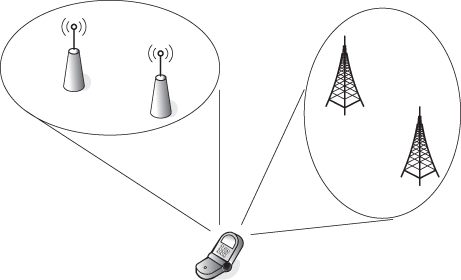
Figure 3.8 The presence of multiple BSs/APs for a limited number of radio interfaces per MT
The work in [132] has investigated this challenge in the context of network capacity maximization. Consider a heterogeneous wireless medium that is composed of two networks, namely cellular network and WLAN, that is, ![]() , where 1 represents the cellular network and 2 represents the WLAN. The set of BSs of the cellular network is denoted by
, where 1 represents the cellular network and 2 represents the WLAN. The set of BSs of the cellular network is denoted by ![]() and the set of APs for the WLAN is represented by
and the set of APs for the WLAN is represented by ![]() . The set of available BSs and APs is denoted by
. The set of available BSs and APs is denoted by ![]() , where
, where ![]() . Each MT,
. Each MT, ![]() is equipped with cellular and WLAN radio interfaces, and
is equipped with cellular and WLAN radio interfaces, and ![]() and
and ![]() denote the set of cellular and WLAN radio interfaces, respectively. MT
denote the set of cellular and WLAN radio interfaces, respectively. MT ![]() asks for a best effort service. Although some of smartphones with dual SIM card are equipped with more than one cellular radio interface, these interfaces cannot be used simultaneously to run two calls, as all cellular interfaces share the same transceiver. Therefore, the MT can have multiple radio interfaces of the same type, but the MT can only utilize one radio interface of one type at a given moment of time. Consequently, the MT can utilize one radio interface from
asks for a best effort service. Although some of smartphones with dual SIM card are equipped with more than one cellular radio interface, these interfaces cannot be used simultaneously to run two calls, as all cellular interfaces share the same transceiver. Therefore, the MT can have multiple radio interfaces of the same type, but the MT can only utilize one radio interface of one type at a given moment of time. Consequently, the MT can utilize one radio interface from ![]() and one radio interface from
and one radio interface from ![]() and can aggregate the offered bandwidth from these two radio interfaces to support its ongoing call. Hence, the problem reduces to specify: (i) a binary user assignment decision variable
and can aggregate the offered bandwidth from these two radio interfaces to support its ongoing call. Hence, the problem reduces to specify: (i) a binary user assignment decision variable ![]() that indicates if MT
that indicates if MT ![]() can connect to BS/AP
can connect to BS/AP ![]() using its radio interface
using its radio interface ![]() (
(![]() ) or not (
) or not (![]() ), (ii) a bandwidth allocation decision variable
), (ii) a bandwidth allocation decision variable ![]() that indicates the amount of bandwidth allocated to MT
that indicates the amount of bandwidth allocated to MT ![]() from BS/AP
from BS/AP ![]() via radio interface
via radio interface ![]() and (iii) a power allocation decision variable
and (iii) a power allocation decision variable ![]() that indicates the amount of power allocated (in the uplink or downlink) on the link connecting MT
that indicates the amount of power allocated (in the uplink or downlink) on the link connecting MT ![]() to BS/AP
to BS/AP ![]() via radio interface
via radio interface ![]() . The binary decision variable constraints (e.g. (3.5) and (3.6)) ensure that an MT connects to a cellular BS using only a (single) cellular radio interface, that is,
. The binary decision variable constraints (e.g. (3.5) and (3.6)) ensure that an MT connects to a cellular BS using only a (single) cellular radio interface, that is,
Similarly, the constraints (3.7) and (3.8) guarantee that an MT connects to a WLAN AP using only a (single) WLAN radio interface. In addition to the aforementioned constraints, the following constraints should be accounted for: (i) capacity limitation of BSs/APs, which accounts for the limitation on the available bandwidth at the BS/AP and (ii) total power consumption constraint (at MT for uplink radio resource allocation or at BS/AP for downlink radio resource allocation). For energy efficiency maximization, the objective function can be expressed by (1.27) for the network operators (i.e. in the downlink radio resource allocation) and (1.28)–(1.32) for the mobile users (i.e. in the uplink radio resource allocation).
The radio resource allocation problem described above is a fractional MINLP due to the binary nature of the MT assignment problem and the continuous nature of the radio resource (bandwidth and power) allocation problem. Hence, higher computational complexity is expected than the approach discussed in the previous subsection. A possible solution relies on exhaustive search, where the MT tries all combinations of cellular network BS and WLAN AP and selects the pair that maximizes the energy efficiency while satisfying the required QoS. However, in a multiuser multioperator system, such an approach incurs high computational complexity and requires high signalling overhead in a decentralized architecture. Furthermore, the heuristic randomization approach proposed in [132] is no longer valid for energy efficiency maximization. The heuristic approach of [132] randomly assigns MTs to BSs and APs and equally allocates the bandwidth available at each BS/AP among the assigned users. However, for energy efficiency maximization, the MT locations and distances from different BSs/APs should be accounted for, which makes the randomization approach not useful in this context. Hence, more efficient techniques should be developed to properly select BSs and APs and allocate the required radio resources.
3.4 Summary
The heterogeneous wireless access medium exhibits great potential in improving energy efficiency while satisfying the QoS of mobile users. Multi-homing services can aggregate bandwidth from different networks, enable better mobility support and reduce energy consumption for mobile users and network operators. In addition to exploiting different channel conditions and path losses among MTs and BSs/APs of different networks, the available bandwidth and operating frequency bands at different networks can further enhance energy efficiency. Hence, a joint bandwidth and power allocation multi-homing approach results in a significant advantage in energy-efficient communications over the power-only allocation scheme. In joint bandwidth and power allocation for uplink and downlink communications in a heterogeneous networking setting, there are many challenging technical issues that require further studies, including fairness in energy efficiency among MTs, achieving mutual benefits among network operators, decentralized implementation with reduced signalling overhead, IDC interference management and implementation complexity. The subsequent chapters are dedicated to address these challenges. Particularly, Chapter 4 investigates achieving mutual power saving among network operators and handling IDC interference management in RF-downlink multi-homing radio resource allocation. Chapter 5 deals with fairness in energy efficiency among MTs, supporting energy-efficient video-streaming applications, and decentralized implementation with reduced signalling overhead and lower computational complexity in RF-uplink multi-homing radio resource allocation. Finally, Chapter 6 studies the adoption of VLC systems in enhancing energy efficiency in the heterogeneous wireless medium via integration with RF networks.