4 Stream graph
In this chapter
- stream fan-out
- stream fan-in
- graph and DAG (directed acyclic graph)
In the previous chapters, AJ has built a streaming job and then scaled it up. It works well for monitoring vehicles on the bridges. However, the structure of the job is quite simple, as the job is pretty much a list of operators. In this chapter, we are going to learn how to build more complicated streaming systems to solve additional problems in the real world.
“Bad programmers worry about the code. Good programmers worry about data structures and their relationships.”
—Linus Torvalds
A credit card fraud detection system
Sid has been impressed by the vehicle counting system AJ built, and he is thinking of new problems to solve with stream processing technology now. The one he is mostly interested in is a fraud detection problem, but he has one concern: the new system will be more complicated and requires very low latency. Can it be solved with a streaming system?

The streaming job built in the previous two chapters is limited in capability. Every data element that enters the job is required to pass through both components in a fixed order: the sensor reader and then the vehicle counter. There is no conditional routing of data for edge cases or errors that could occur in streaming systems. You could visualize the path of the data elements in your streaming job as a straight line.

More about the credit card fraud detection system
In this chapter, we are going to build a credit card fraud detection system. It will be more complicated than the tollbooth problem we had before.

The fraud detection business


Streaming isn’t always a straight line
We can build the system like the tollbooth system. First, the transaction source component is responsible for accepting transaction events from external systems. Then, the analyzers are applied one by one, and risk scores are added into the events. Finally, a score aggregator makes a final decision from the scores.

The solution works, but it is not ideal. New analyzers will be added in the future, the list will grow, and the end-to-end latency will increase. Plus, the job could be harder to maintain when there are many analyzers.

Another option is to build the system like the diagram below. All three analyzers connect to the transaction source and run independently. The score aggregator collects results from them and aggregates the scores to make a final decision. In this solution, the end-to-end latency won’t increase when more analyzers are added.

Zoom into the system

The fraud detection job in detail
Let’s take a deeper look into the fraud detection job and see each component’s responsibility.
How do we know if a transaction is potentially fraudulent?
Fraud scores can range from 0–3. A score of 0 means no fraud is detected by any analyzer, and a score of 3 means fraud is detected by all analyzers. Each analyzer will add a point to the score. We can consider a transaction potentially fraudulent with a score of 2 or greater.

New concepts
In chapter 2, you learned the moving parts in a streaming system, the data sources and the operators, and the connections. We also looked at how the underlying engine handles them. These are all very important concepts that we will keep using through the whole book.
In this chapter, we are going to look into streaming jobs that have more complicated structures. The new diagram looks more complicated than the old straight-line diagram. This is correct, but there is nothing to worry about.

Before moving forward, let’s look at a few new concepts we can learn from this new diagram:
-
Upstream and downstream components
-
Stream fan-out
-
Stream fan-in
-
Graph and DAG (directed acyclic graph)
With these new concepts, we can construct more complicated streaming systems to solve more general problems.
Upstream and downstream components
Let’s start with two new concepts: upstream components and downstream components. They are pretty simple and straightforward.
Overall, a streaming job looks like a series of events flowing through components. For each component, the component (or components, as we will discuss later) directly in front is its upstream component, and the component directly behind is its downstream component. Events flow from an upstream component to a downstream component. If we look at the diagram of the streaming job we built in the previous chapter, events flow from the sensor reader to the vehicle counter. Therefore, the sensor reader is the upstream component, and the vehicle counter is the downstream component.

Stream fan-out and fan-in
Now, let’s look at the new diagram proposed by AJ. It looks quite different from the previous job overall. The major difference is that one component may have more than one upstream or downstream component.
The transaction source component has three downstream components connected to it. This is called stream fan-out. Similarly, the score aggregator has three upstream components (we can also say that the three analyzers have the same downstream component). This is called stream fan-in.


Graph, directed graph, and DAG
The last three concepts we will cover in this chapter are graph, directed graph, and DAG. First of all, a graph is a data structure that consists of a set of vertices (or nodes) and edges (also known as connections or lines) that connect pairs of vertices. Two data structures used by developers, tree and list, are examples of graphs.
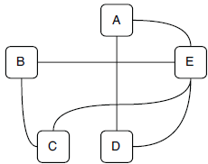
If every edge in a graph has a direction (from one vertex to another one), this graph is called a directed graph. The diagram below is an example of directed graph with five vertices and seven directed edges.
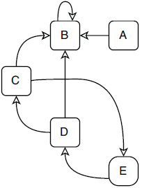
A special type of directed graph is a directed acyclic graph, or a DAG. A DAG is a directed graph that has no directed cycles, which means that in this type of graph, there is no way to start from a vertex and loop back to it following directed edges.

The diagram above is a DAG because from any of the vertices, no path can be found to loop back to itself. In the directed graph diagram, vertices C, D, and E form a cycle; hence, this graph is not a DAG. Note that there is another cycle on vertex B because it has an edge looping back to itself directly.

DAG in stream processing systems
DAG is an important data structure in computer science and in stream processing systems. We won’t jump into too much mathematical detail here, but it is important to know that DAG is a common term in the streaming world.
It is convenient to represent how events flow through a system with a directed graph. A loop in a directed graph means that events can be looped back and reprocessed in the same component again. It needs to be handled very carefully because of the extra complexity and risks. In some cases, loops could be necessary, but they are relatively rare. Most stream processing systems don’t have loops; hence, they can be presented as DAGs.

Note that, from this chapter forward, when we draw a job diagram, we are going to draw a DAG. It will only include the logical components of the job without the engine objects, such as the executors and event dispatchers (unless they are necessary), like in the diagram above, so we can focus on the business logic without worrying about the details in the engine layer. Parallelism is not included either because it is not business logic related.
All new concepts in one page
We have talked about quite a few concepts in this chapter. Let’s put them together in one page, so it is easier to distinguish the relationships between them.

Stream fan-out to the analyzers
It is time to jump into our system now, starting from the stream fan-out part. The stream fan-out in the fraud detection system is between the source component and the analyzer operators. With the Streamwork API, it is straightforward to link the stream coming from the source component to the evaluators. We can connect the source and evaluators, as in the code below.

  Job job = new Job();
  Stream transactionOut = job.addSource(new TransactionSource());
  Stream evalResults1 = transactionOut.applyOperator(new AvgTicketAnalyzer());
  Stream evalResults2 = transactionOut.applyOperator(new WindowedProximityAnalyzer());
  Stream evalResults3 = transactionOut.applyOperator(new WindowedTransactionAnalyzer()); ❶
❶ Multiple operators are applied to the same stream.
Basically, multiple operators, in this case the evaluators, can be applied to the same transaction stream from the source component. In the runtime, every event emitted from the source component will be duplicated three times and sent to the three evaluators.
A stream fan-out is one component with multiple downstream components.
Look inside the engine
The real work happens inside the engine. In the Streamwork engine, when a new operator is hooked up to a stream, a new queue is created between the operator’s event dispatcher and the instance executors of the component that generates the stream. In other words, one instance executor can push events into multiple outgoing queues.

There is a problem: Efficiency
Now, every evaluator should have a copy of the transaction events, and they can apply their evaluation logic. However, this solution is not very efficient.

Each event is a transaction record. It contains a lot of the information about the transaction, such as merchandise id, transaction id, transaction time, amount, user account, merchandise categories, customer location, and so on. As a result, events are relatively large in size:
class TransactionEvent extends Event {
  long transactionId;
  float amount;
  Date transactionTime;
  long merchandiseId;
  long userAccount;
  ……
}
In the current solution, every event is duplicated multiple times because they are pushed to different queues. Because of the different queues, different analyzers are able to process each event asynchronously. These fat events are transferred through the network and loaded and handled by the analyzers. In addition, some analyzers don’t need or can’t process some of the events, but these events are still transferred and processed. As a result, the memory and network resource usage are not efficient and can be improved, which could be important when event traffic is high.
Stream fan-out with different streams
In stream fan-out, different outgoing queues don’t need to be the same as each other. The word different has two meanings here:
-
An emitted event could be pushed into some outgoing queues but skip others.
-
Furthermore, events in different outgoing queues toward different downstream components could have different data structures.
As a result, only the necessary events with necessary fields are sent to each evaluator.

Look inside the engine again
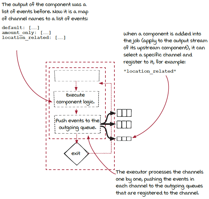
We have learned that one component executor can have multiple outgoing queues. Previously, the executor just pushed the same event to all the outgoing queues connected to the event dispatchers of the downstream components. Now, to support multiple streams, the executor needs to take the events emitted from each component and puts them into the correct outgoing queues.
The component object provides this information via channels. Different events are emitted into different channels, and the downstream components can choose which channel to receive events from.
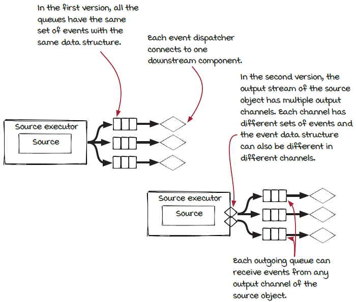
This multi-channel fan-out gives us more flexibility. With more flexibility, we have more options to tune the job to make it more efficient.
Communication between the components via channels
To support this new type of stream fan-out, the component and the executor need to be updated:
-
The component needs to be able to emit events into different channels.
-
The executor needs to take events from each channel and push them into the right outgoing queues.
-
The last piece is that the downstream component needs to be able to select a specific channel when connecting to it via
applyOperator().
Multiple channels
With multichannel support, the fan-out in the fraud detection system can be modified to send only necessary fields in events to the evaluators. Firstly, in the TransactionSource class, channel information can be specified when events are emitted. Note that the same incoming event can be converted into different events in different channels.

eventCollector.add(new DefaultEvent(transactionEvent));    ❶
eventCollector.add("location_based",                       ❷
                    new LocationalEvent(transactionEvent); ❸
❶ The event is emitted into the default channel.
❷ Choose another channel to push events into.
❸ The events in this channel have different data structures.
Then, when an evaluator is added into the streaming job via the applyOperator() function, a channel can be specified first.
Job job = new Job();
Stream transactionOut = job.addSource(new TransactionSource());

Stream evalScores1 = transactionOut
    .applyOperator(new AvgTicketAnalyzer()); ❶
Stream evalScores2 = transactionOut
    .selectChannel("location_based")         ❷
    .applyOperator(new WindowedProximityAnalyzer());
Stream evalScores3 = transactionOut
    .applyOperator(new WindowedTransactionAnalyzer());
❶ A default channel is used when no channel is selected to apply the operator.
❷ A specific channel is selected to apply the operator.
Stream fan-in to the score aggregator
The evaluators receive transaction events and perform their own evaluations. The output of each evaluator is a risk score for each transaction. In our system, the risk scores of each transaction are sent to the score aggregator component to make the decision. If fraud is detected, an alert is written into a fraud transaction database.
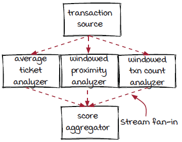
You can see from the diagram that the score aggregator operator takes input from multiple upstream components—the evaluators. You can also think of it in a different way: the output streams from the evaluators are merged, and the events in all of them are sent to the score aggregator operator in the same way. This is a stream fan-in.
One thing worth mentioning is that, in the score aggregator operator, events from different streams are treated in the same way. Another case is that the events in different incoming streams could have different data and need to be used differently. This second case is a more complicated stream fan-in that could be the focus of a full chapter. At the moment, let’s focus only on the simple case.
Stream evalScores1 = ……
Stream evalScores2 = ……
Stream evalScores3 = ……
Operator aggregator = new ScoreAggregator(
    "aggregator", 2, new GroupByTransactionId());
Streams.of(evalScores1, evalScores2, evalScores3) ❶
    .applyOperator(aggregator);                   ❷
❶ Multiple streams are merged into one Streams object.
❷ The ScoreAggregator operator is applied on the Streams object. Note that GroupByTransactionId is a subclass of FieldsGrouping to make sure the scores for a specific transaction are sent to the same aggregator instance.
Stream fan-in in the engine
Stream fan-in is straightforward in the Streamwork engine. The incoming queue of a component (connected to its event dispatcher) can be used by multiple upstream components. When an event is emitted by any of the upstream components (in fact, by an instance of the component), the event will be put in the queue. The downstream component pulls events from the queue and processes them. It doesn’t distinguish between who pushed the events into the queue.

As we discussed before, the queue decouples the upstream and downstream components.
A brief introduction to anotherstream fan-in: Join

We mentioned that, in addition to the stream fan-in used in the example job, there is a more complicated type of fan-in. We will present a brief introduction to it, so you can have a better idea of all types of fan-ins and fan-outs.
In the simple stream fan-in, all incoming events have the same data structure and are treated the same way. In other words, the incoming streams are the same. What if the incoming streams are different from each other and need to be combined together? If you have ever used any databases, you should have some idea of an operation on multiple tables: join. If you don’t know it, or you have forgotten it (we all know how reliable human memory is), no need to worry—it is not a prerequisite.
In databases, the join operation is used to combine columns from multiple tables. For example, a table of user-id and name and another table of user-id and phone-number can be joined to create a new table of user-id, name and phone-number by matching the user-id column in the two original tables. In the streaming world, the basic purpose of the join operation is similar: joining fields from multiple data sources.

However, relative to database tables, streams are much more dynamic. Events are accepted and processed continuously, and matching fields from multiple continuous data sources requires a lot more considerations. We are going to stop here on the basic concept of join and leave further exploration of this topic to its own chapter.
Look at the whole system
Now that we have discussed stream fan-out and fan-in one by one in the previous sections, let’s put them together and zoom out to take another look at the whole system. From a high level, the job can be represented as the graph below; sometimes we call it the logical plan. It represents the logical structure (components and their connections) of the job.

In the real world, fraud detection systems will evolve continuously, and new evaluators will be introduced from time to time. With the Streamwork framework, or other stream processing frameworks, adding, removing, and replacing evaluators is pretty simple and straightforward.
Graph and streaming jobs
With the support of stream fan-out and fan-in, now we can build streaming systems in more complicated and general graph type structures. This is a very important step forward because with this new structure, we can cover more real-world problems.
Here are the DAGs of two example streaming systems. Can you try to imagine what kind of systems they might be?

The example systems
The truth is, these graphs can be so many things! Here are potential answers for the two diagrams.

The first diagram could be a simple traffic monitoring system. The events collected by the traffic sensors are sent to three core processors: an accident detector, a congestion detector, and a junction optimizer. The congestion detector has a location-based aggregator as a preprocessor.

The second diagram could be a fault detection system that processes events from sensor readers in multiple versions. The events generated from the first two versions are not compatible with the detector; hence, an adapter is needed for them. In the system, all the sensor readers can work together seamlessly, and it is easy to add new versions or deprecate old versions.
After all, stream jobs are not very complicated. The example systems are significantly simplified compared to the real-world systems. Nevertheless, hopefully you have a better idea of what streaming systems can do now. In their simplest form, streaming jobs are components and their connections. Once a streaming job is set up and running, events flow through the components along the connections forever.
Summary
In this chapter, we moved forward from the list type system structure we discussed in previous chapters to a more general type of system structure: the graph. Because events flow through systems from the sources to the operators, in most cases a streaming job can be presented as a directed acyclic graph (DAG). Most jobs in the real world have graph architecture; hence, this is a critical step.

Different from the components in the list type system structure, in a job graph, a component can link to multiple upstream components and downstream components. These types of connections are called stream fan-in and fan-out. The streams coming into a component or going out of it could have the same types of events or different types.
In addition, we also looked at the Streamwork framework a little bit to see how the engine handles the connections. Hopefully, this will be helpful for your understanding of how streaming systems work in general.
Exercises
-
Can you add a new evaluator to the fraud detection job?
-
Currently, each evaluator takes a transaction event from the transaction source component and creates a score. Now two evaluators have the same type of calculation at beginning of their evaluation. Could you change the job for this case? The result will look like the graph below:
