
An Illustration of HAZOP Study for a Procedure
Abstract
A detailed description of all the stages of a HAZOP study of a procedure, namely, a one-off removal and replacement of a section of a hydrocarbon pipeline. The preparation and sequence are described as well as the selection of nodes with their design intentions. The selection of guidewords and their application to two of the nodes are shown along with the HAZOP reports and a list of the key findings.
Keywords
Procedure HAZOP; node selection; design intention; HAZOP report.
This study is loosely modeled on an article in the ICI Safety Newsletter No 32 August 1971. As the study is “hypothetical,” the working parameters of the up- and downstream processes are not available but this should not detract from demonstrating the study process. Also, as the study is clearly short and operations oriented, it does not justify a full team and the Facilitator may also act as Scribe. With the limited number of team members, some of the actions must be dealt with by someone outside of the study group who has the skills so to do. It is the responsibility of the person named in the study records to ensure that a competent person answers them and that they are implemented properly.
A5.1 Background
This example is based upon the HAZOP study of a planned modification of an existing process operation (Figure A5.1).
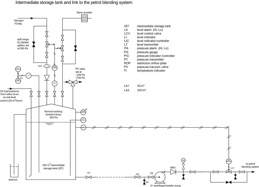
An intermediate storage tank (IST) receives a C6 hydrocarbon stream (averaging 25 m3/hour) from the reflux drum of an atmospheric pressure distillation column, run down on exit level control via the reflux pumps into the 250 m3, nitrogen-blanketed tank. This conical-roofed tank serves as a buffer and temporary storage for the material before the C6 material is pumped by the J1 centrifugal pump, on level control, to the plant petrol blending unit. The IST operates at ambient temperature and at 500 Pa on split range pressure control and is inerted by nitrogen from the 1.3 bar site nitrogen supply. The tank is protected by a pressure (vacuum) valve (PV) set at −250/+750 Pa. It is in a bunded enclosure with an overflow, sealed with glycol, which empties into the bund. There is adequate instrumentation, including level indication with high- and low-level alarms and high-level trip plus temperature and pressure indication, all to the site control room. Figure A5.1 gives sufficient detail for the Procedural HAZOP and any deficiencies are outwith the scope of the study.
The modification is planned to remove the 100 m length of 100 mm diameter piping between the tank master isolation valve, V1, and the first pump isolation valve, V2, and to refit the pump closer to the tank, but first the flammable fluid (about 0.8 m3) must be removed. Consideration was given to draining it into a drum but the risks were considered to be unacceptable. In line with the corporate management of change policy, a Hazards Study approach (see Chapter 2) was adopted.
1. The inherently safer option (HS 0) of displacing the fluids with nitrogen has been adopted. There is a nitrogen ring main on the site which can be connected below valve V4. This link is fitted with a non-return valve at the hose connection.
2. During the HS 2 analysis (FEED), it was recognized that this was a non-standard operation with potential human factors (see Section 10.2). It was recommended that all valves should be clearly labeled (V1, etc.) and that a dummy run practice should be carried out to debug the procedure and to familiarize the crew with the operation.
3. During the HS 3, it was decided that a HAZOP study should be carried out.
The final arrangement below (Figure A5.2) shows the 100 mm diameter suction line, the 25 mm diameter nitrogen header and a flexible hose, and 18 mm diameter depressuring line with an isolation valve V6. All piping other than the hose will be hard piped.

An operational procedure has been drawn up which, in accordance with the MOC policy, is to be the subject to a Procedural HAZOP.
A5.2 Detailed Proposed Sequence
The operation will be carried out by an operator stationed near J1 who will be the lead operator and a second operator, in radio communication, at the tank to operate valve V1. The lead operator will control the procedure.
The initial set-up is for all valves V1–V6 closed and with the line between V1 and V2 containing C6 liquid.
1. Open V6 then open V5 to prove line clear of debris and to displace any air in the hose.
3. The operator at the J1 pump should open V2 slowly until fully open.
4. The operator at the tank is then instructed to open V1 slowly by one or two turns.
5. The operator at V1 should wait until nitrogen is heard passing through the valve into the IST then the tank operator will close V1.
6. The tank operator should then cautiously reopen V1 by one or two turns to ensure as much liquid as possible has been blown back to the IST.
8. Close V1 after allowing any residual N2 in the line to depressure into IST.
9. Pump-based operator to close V2.
11. Verify V2, V4, and V5 are all closed.
A5.3 The HAZOP Study
• Mike Manchester (MM) Facilitator and Scribe
• Brenda Bolton (BB) Production Manager
Division into nodes
• Steps 1–2: Connect and prove the nitrogen supply. V5–V6.
• Design intention: To prove that the N2 supply is fitted and to displace any air in the hose.
• Steps 3–9: Clear the line by blowback to IST. V5–V1.
• Design intention: To completely clear petroleum feedstock from the 100 m line between the J1 pump and the IST by blowback to the IST using N2 from the 1.3 barg nitrogen ring main via a temporary connection fitted to an existing drain by the J1 pump. Manual control by operators positioned at each end of the line. After the main clearance, a brief second flush will be applied.
• Steps 10–13: Depressurize and disconnect. V1–V6.
• Design intention: Line previously containing C6 but now containing N2 to be depressured.
Table A5.1
HAZOP study report for node 1 (to be read in conjunction with figures A5.1 and A5.2)


Table A5.2
HAZOP study report for node 2 (to be read in conjunction with figures A5.1 and A5.2)


Table A5.3
HAZOP study report for node 2, final blow through, steps 6–9 (to be read in conjunction with figures A5.1 and A5.2)
(Immediate continuation of node 2 after first nitrogen flush of the line, i.e., completion of step 5.) Status: As at the end of main blow through. V1, V3, and V6 closed; V2, V4, and V5 open. Team/date as Table A5.2. |


A5.4 Final HAZOP Study Report
Obviously, the final report cannot be written until the full HAZOP study has been completed. However, it is clear that there are a number of steps with potential for errors (human factors), it being a one-off operation and unfamiliar to the operations staff. There are also a number of “unknowns.” Displacement (or blowing through) is a standard operation but it has significant implications when carried out within the constraints of this procedure. Is it a viable solution?
To date the key findings from nodes 1 and 2 are:
1. The procedure has missed the natural hogs and hollows in the line between V1 and V2 and any elevation changes between the nitrogen injection point and the IST which may make the procedure nonviable.
2. There is potential for release of C6 at V6.
3. A possible overpressure of the IST following a N2 blow-by.
4. Step 4 is vague—one or two turns is not a measurable parameter so there is potential for human error/factors.
5. The flow regime in the line from V2 to V1 is uncertain, and it is not clear that the contents can be displaced in a controlled manner. There is a potential conflict between transport of C6 and IST integrity. Is there a better alternative?
6. The compatibility of the radios with the Hazardous Area Classification.
7. It is a new one-off operation which needs some training (human factors).
8. There is a need for labeling of all the valves (human factors).
9. The interpretation of the “end of clearing” using a subjective “noise” (human factors) is not inherently safe.
10. There is a possibility of recontamination of the line following the final blow out due to hydrostatic head in IST if the closure of V1 is delayed. The line V1–V2 must not be blown down into IST due to the risk of recontamination. V1 must be closed first.
A5.5 Authors Notes on this Procedure
Valve V1 is a gate valve as the procedure says “open two turns.” Assuming that it is mounted vertically, the flow regime in the line from V1 to V2 will be very uncertain as the gap for liquid flow will be at the bottom of the line, and this will not necessarily be the low point—there could be “hogs and hollows” in the line especially if it slopes to the pump J1. A foam pig would pass the fully open gate valve V2 and be stopped by the partially open gate valve V1 (open one or two turns). This method would give a more complete line clearance and so a pig run may be preferable.
The objective of this exercise was to demonstrate the use of HAZOP in a procedure, but it has produced more issues than expected! This shows the strength of HAZOP.