
Software Engineering for Model-Based Development by Domain Experts
M. Bialy1, V. Pantelic1, J. Jaskolka2, A. Schaap1, L. Patcas1, M. Lawford1 and A. Wassyng1, 1McMaster University, Hamilton, ON, Canada, 2Stanford University, Stanford, CA, United States
Abstract
Model-Based Development (MBD) has been gaining traction in the development of embedded software in many industries, especially in safety-critical domains. The models are typically described using domain-specific languages and tools that are readily accessible to the domain experts. Consequently, domain experts, despite not having formal software engineering training, find themselves creating models (designs) from which code is generated, thus effectively contributing to the design and coding activities of software development. This new role for domain experts as software developers can have a direct impact on the system safety if the domain experts do not follow software engineering best practices. In this chapter, we describe our experiences as software engineers in multiyear collaborations with domain experts from the automotive industry, who are developing embedded software with the MBD approach. We provide guidelines that strengthen the collaboration between domain experts and software engineers and improve the quality, and hence safety, of embedded software systems developed using MBD. We clarify the role of some of the most commonly used software engineering principles and artefacts, while also addressing issues and misconceptions encountered in adopting software engineering practices in MBD. Although this chapter focuses on the MBD of automotive embedded software in Matlab Simulink, the guidelines we provide are applicable to the MBD of software in general.
Keywords
Software engineering; domain experts; functional safety; embedded software; model-based development; Simulink; automotive
3.1 Introduction and Motivation
Early in the computer age, it was recognized that an ad hoc programming approach was not suitable for developing nontrivial software systems. In the words of a famous computer scientist, Edsger Dijkstra: “To put it quite bluntly: as long as there were no machines, programming was no problem at all; when we had a few weak computers, programming became a mild problem, and now we have gigantic computers, programming has become an equally gigantic problem.” Therefore, a systematic engineering approach including planning, problem understanding, requirements gathering and specification, design, programming, and verification became necessary. This is how software engineering was born. According to ISO/IEC/IEEE Standard 24765 [1], software engineering is defined as, “The application of a systematic, disciplined, quantifiable approach to the development, operation, and maintenance of software, that is, the application of engineering to software.”
Unfortunately, decades later, software development and maintenance is still not practiced with the same discipline exercised in other engineering fields. Developing software is often deemed trivial by nonpractitioners. This perception is mostly due to software’s malleability. Since software itself is not physical, a modification to software is considered “merely a code change.” This perception, however, is wrong. Experience teaches us that software should be modified with the same rigor as any other engineering product, e.g., an engine, power inverter, or airplane brakes. The effect of a change should be evaluated on a design first, and then thoroughly verified. This is an approach especially necessary in modern systems, which increasingly rely on software. Software accounts for 80% of military aircraft functions [2] and 80% of innovations in vehicles [3]. Software has also grown to be a significant source of accidents and product recalls [4]. Moreover, numerous examples of software-related accidents span the safety-critical domains of aerospace [5], medical [6], and automotive [7], with many more examples listed in [8,9]. For such safety-critical systems, errors can potentially result in loss of life, environmental damage, and/or major financial loss. Therefore, practicing software engineering with the same rigor and discipline recognized in other areas of engineering is crucial to the successful development and safe operation of modern software-intensive systems.
Model-Based Development (MBD) has become a predominant paradigm in the development of embedded systems across industries, including aerospace, automotive, and nuclear. This is mostly due to its appeal of automatic code generation from models, early verification and validation, and rapid prototyping. Furthermore, domain-specific modeling languages used in MBD are easily learned and used by domain experts (experts in the field of the application), allowing them to design, generate code, and verify their own algorithms, using familiar terminology and abstractions. Therefore, the MBD paradigm assigns domain experts a different role than the one they typically have in a traditional software development process. However, domain experts have backgrounds in mechanical engineering, electrical engineering, or other related fields, but typically have no formal education in software engineering. For example, many leading Japanese software specialists believe the majority of Japanese software developers have not been formally educated in software engineering [10].
Our work builds on experience drawn from collaborations between our team of software engineers and domain experts in the automotive industry. While working on multiyear projects with automotive Original Equipment Manufacturers (OEMs), we have interfaced with a number of domain experts from both academia and industry.
First, we have witnessed a large difference in terminology used by software engineers and automotive domain experts1. We (partially) address this communication gap between the two communities by explaining the terminology originating in software engineering that is commonly used in development of embedded systems.
Second, domain experts use and/or help develop various software artefacts, often without a clear picture of their intent and their ultimate effect on the quality of software.
This chapter clarifies the role of some of the most commonly used (and those that are not, but should be) software engineering principles, practices, and artefacts by viewing them from a software engineering perspective, and presenting how they affect software correctness, safety, and other software qualities. Therefore, this chapter aims at strengthening the collaboration between software engineers and domain experts, by offering domain experts a high-level understanding of software engineering practices and artefacts, enabling their more effective use. In the process, a number of MBD misconceptions and limitations are addressed. Further, we discuss issues in the industrial practice of MBD, and suggest solutions whenever possible, or point to avenues for research to address issues for which a solution currently does not exist. The chapter is focused on the development of embedded software using Matlab Simulink, the de facto standard in model-based design of embedded systems. Ironically, Simulink itself neglects some major software engineering principles, and this issue is also discussed in this chapter. While the focus of this chapter is on the MBD of embedded systems using Matlab Simulink, many of the discussions are applicable to software engineering in general. Therefore, we view this chapter as a useful tutorial primarily for domain experts involved in the development of software intensive systems, but also for software practitioners in general, managers in related fields, and any staff involved in software and/or software development.
The remainder of this chapter is organized as follows. Section 3.2 describes the overall MBD software engineering process and serves as a prelude to the subsequent sections. The subsequent sections, Sections 3.3, 3.4, 3.5, and 3.6, then provide insight into commonly encountered questions and misconceptions in industry regarding requirements, design, implementation, and verification and validation, respectively. Finally, Section 3.7 presents conclusions and directions for future work.
3.2 Development Process: How Do You Engineer Software?
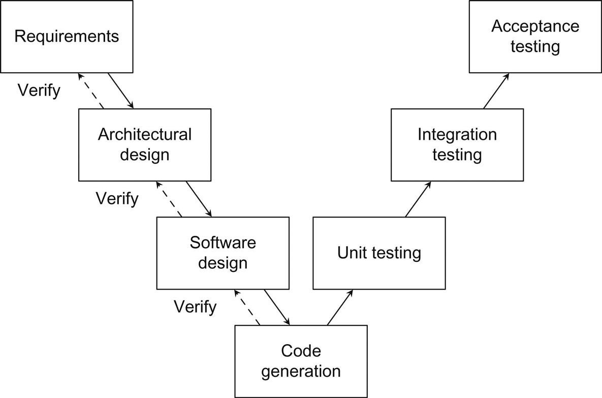
Software is not only code, and developing software is not just programming. Software includes requirements, design, test reports, and other documentation which are artefacts resulting from the different phases in the engineering process. As with all engineering disciplines, well-defined processes must be followed in order to construct quality systems which operate safely. The most common description of the software engineering process within the MBD of embedded software is known as the V-model, shown in Fig. 3.1. Although many process models exist for software systems, the V-model is the most widely accepted model for embedded safety-critical systems because of its focus on testing at different levels. Moreover, standards such as the automotive standard ISO 26262 [11] prescribe its use. In this section, we provide a summary of the phases of the V-model which are further elaborated in the sections that follow.
3.2.1 What Are the Phases of the Engineering Process? How Are Domain Experts Involved?
The development process begins with the gathering and specification of requirements. In this phase, a high-level description of what the system should do is determined, without providing any details as to how it is done. As a result of the requirements phase, a software requirements specification (SRS) is produced and agreed upon in order to act as a contract between stakeholders and developers, that is, a mutual agreement of the expectations from the system. This phase typically involves close collaboration between software engineers, analysts, managers, with domain experts providing technical breadth and depth within their respective domains. For example, our experience is that a separate team of safety experts plays an integral role in contributing to the development and analysis of safety requirements for automotive systems.
Once a working set of requirements for the system has been established, a high-level architectural design is planned. The architectural design should strive to integrate principles of software engineering (e.g., modularity and encapsulation), that will be further explained in Section 3.4, in order to minimize complexity and facilitate component reusability. Again, managers, software engineers, and domain experts are primarily involved at this stage, with third-party suppliers also participating where necessary. Architectural design is then verified by way of reviews, simulations (if the corresponding executable specification exists), etc. Next, a software solution that satisfies the requirements and conforms to the architectural design is developed. In MBD, this is largely done by constructing models in accordance with language guidelines and standards. This phase includes defining the necessary component modules, algorithms, data structures, and other detailed design elements necessary for the implementation (or in the case of MBD, code generation). In practice, one or more components or modules are assigned to an individual to “own,” that is, to develop and maintain. In current MBD practice, we have found that domain experts design software and rapidly prototype designs, which are later transferred to other engineers to prepare for production as well as maintain. Ideally, these software development activities should be performed by software engineers. They will be well-versed in implementing software using accepted engineering best practices and principles. Close collaboration with a domain expert, knowledgeable about the domain-specific context, will provide guidance toward a solution.
A major benefit of the MBD approach is the ability to automatically generate the implementation code from design models. This significantly reduces implementation errors and development time when compared to traditional programming [12], and also enables domain experts’ deep involvement in the development process. The same component “owners” responsible for designing the software will generate its corresponding code. If needed, another separate team of engineers may be responsible for code generation rule customization, which typically comes from the recommendations and suggestions of domain experts. After generating an implementation of the software system, verification takes place to ensure that the system that is implemented is the one that was designed and expected. MBD offers the ability to perform tests early in the development cycle, at different levels, before the software even makes it onto the hardware. There are various stages of testing which occur throughout the development process. For example, unit testing verifies each software component individually and independently from the rest of the system, whereas integration testing combines software components to verify the system as a whole, and acceptance testing verifies that the system satisfies its requirements and performs as expected. In general, the embedded system under development is modeled as a controller, which aims to control some physical system using supervisory logic. The physical system is described in a plant model, which provides the controller with inputs. Depending on the development stage of the controller and the platform upon which the plant is simulated, different testing strategies can be utilized throughout the MBD process:
Model-in-the-Loop (MiL): The controller and plant models are simulated in their development environment (e.g., Simulink).
Software-in-the-Loop (SiL): The controller embedded code, generated from the model into hardware-dependent code, is simulated with the plant model, both on the same machine, typically on PC hardware.
Processor-in-the-Loop (PiL): The controller embedded code is loaded onto the embedded processor (hardware), and is simulated with the plant model in real time.
Hardware-in-the-Loop (HiL): The controller embedded code is run on the final hardware, an electronic control unit (ECU), with a simulated plant model in real time.
The phase following software release is maintenance (not depicted in Fig. 3.1), where either defects are fixed or software is modified to satisfy new requirements. In fact, ease of maintenance (maintainability) is one of the very important qualities of software, that, although often not explicitly required, motivates many of the activities in the development process from Fig. 3.1. Software is maintained through collaborative efforts between domain experts and software engineers. For example, in some companies, a software engineer will be in charge of maintaining a software feature (Simulink model). The software will be modified in collaboration with a domain expert, typically in charge of several similar features (Simulink models).
3.2.2 How Important Are the Tools?
Appropriate tool support in each phase of the process by way of a comprehensive tool-chain that facilitates different activities, including change management, build management, bug tracking, etc., is crucial for the success of a development process [13]. Engineering a system often requires many iterations of the development process and its phases. For example, as the software design is developed, requirements can change, making it necessary to go back and repeat the requirements phase. In fast-paced industries such as automotive, performing such iterations quickly is greatly facilitated through the use of tool-chains which span the entire process, and can fully- or semiautomate designing and implementing changes.
3.2.3 An Illustrative Example: Transmission Control Software
For the purpose of illustrating and highlighting the software engineering process for MBD described in the remainder of this chapter, we will consider a small automotive example that was provided by one of our industrial partners, as presented in [14]. Suppose that we need to design and develop the embedded software to control the automatic transmission system of a hybrid-electric vehicle based on requests made by the driver to change gears between park (P), reverse (R), neutral (N), and drive (D) via a “PRND” shifter, typically in the form of a lever or knob within the vehicle console. When using the vehicle, a driver makes requests to change the transmission gear via the shifter (e.g., switch from park to drive), at which point the embedded software needs to decide whether or not to grant the driver’s request based on a number of system conditions, such as faults and the availability of certain components. In the subsequent sections of this chapter, we will use this simple illustrative example to demonstrate how to specify software requirements, to translate those requirements into suitable model-based designs, and to verify and validate that the implemented design exhibits the expected system behavior.
3.3 Requirements: What Should Your Software Do?
3.3.1 How Important Are Good Requirements?
Contrary to common belief, software rarely fails. More often than not, the software behaved exactly as it was required to, but it was the requirements that were flawed [15]. Some sources assert that over 90% of software issues result from deficient requirements, leaving merely 10% of issues to be caused by design and coding problems [16]. Therefore, experience teaches us that getting requirements right as well as precisely specifying them is essential for the establishment of safe and effective systems [17]. The terms “requirements” and “requirements specification” are taken from software engineering, and are not a part of domain experts’ jargon. Our experience shows that domain experts would rather refer to it as “specification” or “spec” only.
3.3.2 What Is the Purpose of a Requirements Specification? Who Uses It?
Before building a safe and usable system, an understanding of what it is meant to accomplish and what qualities it should possess is required. Requirements specify what the system should do, and a SRS is an artefact in which software requirements are documented and maintained. A requirements specification acts as a contract between users and software developers. It is also used by verifiers to show that the software satisfies its requirements and by managers to estimate and plan for resources. In our experience, the requirements specification is essential for helping mitigate the impact of developer turnover, especially within the automotive industry which experiences frequent movement of personnel.
3.3.3 Simulink Models Are NOT Requirements
Requirements should state what the system should do, whereas design and code state how. In practice, however, while the line between the two is not always clear, even in traditional development approaches, it is significantly blurred in MBD. For example, a Simulink model is often considered both the requirements specification and the detailed design specification. Graphical models are often used to help understand requirements. They may also provide a convenient means for facilitating communication between domain experts and software developers. However, Simulink models are not requirements. Simulink models contain too many design (implementation) details, making it difficult to see the black-box behavior of a system. Furthermore, a Simulink model lacks a means for specifying nonfunctional requirements and properties of the system (e.g., confidentiality).
3.3.4 What Is Wrong With Requirements Specifications Today?
Many organizations using MBD recognize the importance of separating requirements specification from design. However, the requirements are often written using natural language, and are therefore bound to be ambiguous. Furthermore, the requirements are often incomplete, that is, they specify the required functionality of the system for particular combinations of inputs, but often fail to specify the functionality for all the combinations.
We have also often seen inconsistent requirements specifications, that is, those containing contradictory statements. Using a language with precise syntax and semantics (meaning) helps alleviate these issues. Consider, for example, the requirement captured in the tabular expression [18] shown as Table 3.1. Tabular expressions are one of many ways to specify requirements. However, they offer precise and concise semantics, and are used in the nuclear and aerospace industries due to their understandability. They can be interpreted straightforwardly as if-then-else statements. Consider writing a requirement for driver request arbitration from the Park position in the illustrative example described in Section 3.2.3 that states: “If there is no fault and the component is unlocked, grant the driver’s request; otherwise, stay in the current gear.” This requirement can be compactly specified as a tabular expression for the Park position as shown in Table 3.1, where each row represents a subexpression of the function such that if a Condition is evaluated to be true, the corresponding Result cell value is the returned output.
Table 3.1
Requirement for Driver Request Arbitration From Park
| fArbRequestFromPark(eDrvrRequest:enum, bUnlocked, bFaulty:bool): enum= |
 |
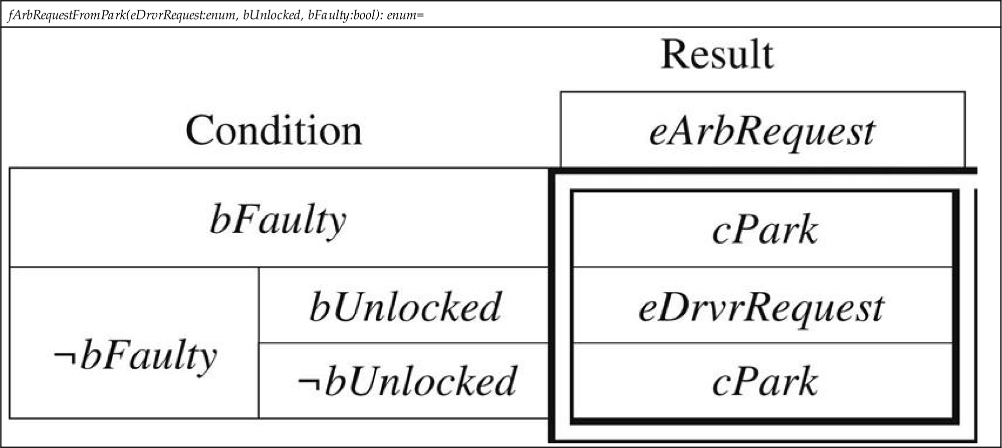
Given the requirement specified in Table 3.1, it is straightforward through the use of tool support [19] to verify that the requirement is complete (requiring consideration of all possible inputs) and consistent (ensuring determinism through nonoverlapping input cases), both of which are integral to safety-critical systems, as they raise the confidence in correct system performance in all conditions, and also aid in detecting gaps for the input cases considered.
3.3.5 Who Writes the Requirements Specification?
Ideally, domain experts would write the requirements specification themselves, without the help of software engineers. However, this is seldom the case, with software engineers producing the requirements specification based on communication with domain experts. The knowledge of the domain experts is instrumental to the specification of requirements, but the developer possesses the knowledge of how to specify the requirement precisely and succinctly. While getting requirements right necessitates continual interaction between domain experts and software engineers, there is commonly a disconnect, as they often do not “speak the same language.” Specifying requirements such that they are understandable to domain experts, and the use of notations like the aforementioned tabular expressions are integral to the development of a quality requirements specification. MBD notations like Simulink/Stateflow have proven to be useful in this regard, given that they are readable by both domain experts and software engineers.
3.3.6 What Information Should an SRS Contain?
The structure and content of a SRS have been thoroughly investigated, with several standards and templates available [20]. At minimum, an SRS typically consists of the following elements:
Purpose: A clear statement of the system’s fundamental reason for existence. This is meant to provide a rudimentary understanding of the system and why it is needed.
Scope: Includes a brief overview of the system to be developed and should indicate the goals and benefits of building the system. It also specifies the boundaries within which these goals are met. An accurate scope definition is important since it is often used by project managers to determine timing and budget estimates.
Functional Requirements: A functional requirement specifies an action or feature that needs to be included in the software system in order for the system to be fit for purpose. Table 3.1 is an example of a functional requirement.
Nonfunctional Requirements: A nonfunctional requirement specifies a property or quality that the software system shall possess in order to judge its operation. Nonfunctional requirements often specify the performance, security, and usability requirements of the software system, among others.
An SRS should also contain specifications of the tolerances on accuracies of outputs, rationale justifying the reason for the existence of requirements (with alternatives considered, if any), specifications of interfaces documenting how the software communicates with its environment, and documentation of anticipated changes to existing requirements so that they may be better accommodated by the eventual design.
Once a preliminary set of requirements can be agreed upon by the domain experts and other stakeholders, and there is a general understanding of what the system must do, thought can start being put into how the system is going to do what it does. It should be noted that requirements specification is an iterative process that continues in subsequent phases.
3.4 Design: How Will Your Software Do What It Does?
Designing software is similar to design activities in other engineering fields. It is the process of determining how a system will perform its intended functions. The software design process is regularly comprised of two stages: architectural design and detailed software design. The design starts with determining the software architecture, which is the description of the high-level decomposition of the system into its main components, their interfaces, and interactions between the components. Software architecture is then gradually refined into a detailed design of modules and algorithms. In MBD, the software design refers to the modeling of the software in a language such as Simulink/Stateflow, with the models effectively serving as blueprints for the software implementation, done via automatic code generation.
3.4.1 How Is Design Different From Requirements?
Design is directly driven by the requirements gathered in the previous phase. Models are created and continually modified until a design has been achieved that meets all the requirements. Although closely tied together, it is important to emphasize again that requirements are not the same as design models. As previously mentioned, this is one of the most prevalent misconceptions when it comes to MBD, with MathWorks also perpetuating this idea in the recent past [21]. Requirements and design must be viewed as separate entities, and we can illustrate exactly why using the automotive example given in Section 3.2.3.
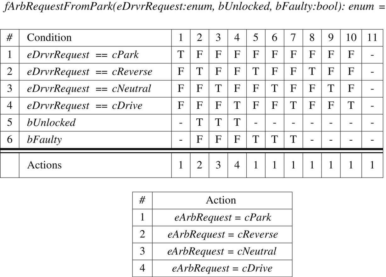
Table 3.1 specifies a requirement, while Tables 3.2 and 3.3 provide two detailed Stateflow designs which both satisfy this requirement. These Stateflow truth table designs are structured in two sections, where the top subtable defines conditions to check. Should the conditions be evaluated to the values given in the columns, (T, F, or -, representing true, false, or “don’t care,” respectively), the corresponding action for the column is executed. Actions are defined in the bottom subtable. It is apparent that pinpointing the requirement within these designs is difficult due to the additional design details also included. Moreover, this example demonstrates that multiple, yet distinct, designs can implement the same requirement in different ways. For these reasons, it is imperative to document requirements separately from design. Just as in engineering in general, the motivation for choosing one design over another will lie in the added need to satisfy other requirements or accommodate constraints. For example, if the component containing design implementing the requirement from Table 3.1 has a tight timing requirement, the second design may be used due to its more efficient condition checking. However, if maintainability over different, but similar, software versions containing this component, is the bigger concern, the first design will more likely be used, as will be explained later in this section.

3.4.2 What Are Important Principles of Software Design?
It is well known in software engineering that good designs lead to high-quality software systems. For systems other than trivial examples, it is necessary to decompose, or break up, the system into manageable modules in order to improve its reusability, overcome complexity, and to divide labor. There are typically several ways of decomposing a system. The criteria used in the decomposition of a system plays a significant role in determining the quality of a design. One of the most important principles in software design is design for change [22] which prescribes that a developer needs to be able to anticipate changes that the system might undergo, and design software capable of accommodating those changes. For example, when designing powertrain software, engineers need to anticipate powertrain configurations that might have to be supported in the future, and design software so that, if the change is made, the effect of the change will be localized as much as possible. Closely related to the design for change and anticipation of change principles is the concept of a software product line. A product line necessitates a core architecture of common functionality across the various configurations, but will also provide the ability to include variations in order to create different products within the line. For example, a large part of electrified powertrain software can be reused throughout different powertrain configurations. All of the software versions corresponding to different powertrain configurations will constitute products within a software product line. As another example, the model shown in Table 3.2 was developed to satisfy the requirement from Table 3.1, but was also devised with the product line approach in mind, because the logic it implements varies only slightly with different vehicle variants. More precisely, while the conditions listed in the columns of the first table of Table 3.2 remain the same for each product in the product line, the set of actions on these conditions is the only part of the design that varies throughout the different products within the product line. Roughly speaking, the actions are encoded as calibrations, so that they are easy to change, and maintain. Calibrations, in fact, are often used to implement variability in software across products within a software product line.
The mechanism crucial in implementing design for change in software engineering is information hiding [22]. Information hiding seeks to decompose a system such that modules each “hide” a requirement or design decision that is likely to change, that is, the interface of the module does not reveal its inner workings. Typically, design decisions creep into the interfaces of the modules, making them context-dependent, and not easily modifiable or reusable. Design decisions typically correspond to hardware, behavior, and software design decisions which are likely to change in the future, and hiding their details within a module will make future changes easier to accommodate. Continuing with the aforementioned electrified powertrain software example, a module that will “hide” the powertrain architecture from the rest of powertrain software represents a hardware hiding module. However, while the principle of information hiding has fared well in traditional software development paradigms, it might not be as useful and widely applicable in MBD. We are currently undertaking research into the role of information hiding in MBD.
3.4.3 How Does Simulink Support the Application of Software Engineering Principles?
For MBD, Simulink enables the introduction of various levels of hierarchy in order to decompose a system into various levels of abstraction. Unfortunately, a challenge in Simulink is understanding how to employ information hiding, how designs will benefit from it, as well as how to decompose a system into reusable modules. The subsystem is the accepted Simulink equivalent of a module, however, they are neither reusable, nor do they effectively encapsulate their internal design. Degrees of reusability can be achieved with other mechanisms such as libraries, model references, function-call subsystems, code reuse subsystems, and Simulink functions, however, they all fail to encapsulate their internals with respect to hidden data flow [23]. For example, Data Store Memory blocks are able to bypass the typical inport/outport interface of a subsystem, and read/write data directly from/in the subsystem. Adding explicit interfaces which include Data Store Memory blocks such as those described in [23] can alleviate this problem. However, a new block mechanism within the Simulink language is needed; one which restricts hidden data flow to effectively encapsulate data, as well as be easily reused in multiple locations of a model. Such a mechanism is not currently available and presents itself as a challenge when employing information hiding in Simulink designs. Research into the development of such mechanisms is needed.
Furthermore, Simulink lacks self-documenting capabilities of imperative programing languages. For instance, an analog of a module interface in C, as defined in C header files, does not exist in Simulink [23].
3.4.4 How Can Guidelines Help?
When it comes to achieving a good design, as with most languages, there are conventions and guidelines available which give best practices that should be adhered to. Likewise, for Simulink/Stateflow, standards such as [24,25] have been developed with the aim of facilitating desirable model qualities, mostly readability. Making models readable with appropriate block colors and positions is comparable to including white spaces and new lines in textual languages, and makes a difference when it comes to achieving qualities such as modifiability and maintainability.
Nevertheless, in working with industrial-sized models from OEMs and the currently available guidelines, we have noticed shortcomings in the guidelines in addressing actual design principles, such as modularity. For example, using global variables in traditional programming languages is strongly regarded as bad practice because global variables hinder encapsulation, reuse, and understandability. However, modeling guidelines for Simulink typically do not recommend against the use of analogous constructs such as Data Store Memory blocks at the top-level of models (which would be analogous to them being declared as global variables), or above their needed scope. Such a recommendation can easily be formulated and automated, as done in Ref. [26] with the Data Store Push-Down Tool. In general, more guidelines and supporting tools are needed, which aim to increase the use of other important software engineering principles.
3.4.5 What Information Should a Software Design Document Contain?
As with other traditional development approaches, designs in MBD must be properly documented. A software design description (SDD) is an artefact documenting the design of the software system and describing how the system will be structured in order to satisfy its requirements. An SDD effectively translates the requirements from the SRS into a representation using software components, interfaces, and data. Commonly used templates which outline the content and format of compiling an SDD exist [27]. At minimum, an SDD typically consists of the following elements:
Purpose: A clear statement describing what the system is ultimately meant to accomplish. It is meant to reinforce the understanding of why the system needs to be developed.
Rationale: Provides justification for the chosen design. This often includes a description and justification of the design decisions that were made in the development of a module, and a list of the alternatives that were considered, along with reasons why they were rejected.
Interface Design: Describes the intended behavior of a module from an external viewpoint, such that other entities can interact with the module without knowing its internal design. This should include the any imported modules, inputs, outputs, and their types, ranges, etc.
Internal Design: Describes the internal structure of a module, including subsystems, algorithms, internal variables/data, and constants.
Anticipated Changes: A list of the ways in which a module is expected to change in the future. This offers insight into the future direction of the development of a module. In this way, one can design for change so that when requirements of the system change, the design can accommodate those changes with only moderate modifications, rather than with complete overhauls.
Although the need for documenting Simulink models has been recognized in industry, to the best of our knowledge, there has not been any research on how this is to be done. Our own efforts show that the principles and content of an SDD from traditional software engineering equally apply to documentation of Simulink models, and we have been working to develop a template for an SDD for Simulink models.
3.4.6 Are Models Documentation?
In MBD, we are often met with the “models are documentation” fallacy that we believe has further perpetuated the lack of proper documentation across industries using MBD. However, any engineer responsible for maintaining real-world industrial-size Simulink models understands that a Simulink model is notoriously hard to reverse engineer or maintain without additional information about the model that can be documented in an SDD. For example, Simulink lacks facilities to explicitly represent the interface inputs/outputs of a model/subsystem. This issue was discussed and suggestions were made in [23]. Also, a model does not contain rationale for design decisions. However, experience teaches us that documenting rationale is crucial for proper software development and maintenance.
We illustrate the importance of having a good SDD by an anecdotal story from our collaboration with one of our industrial partners. Their newly hired engineer was tasked with maintaining a Simulink model implementing algorithms within his expertise area. There was no documentation associated with the model. Although the engineer was very familiar with the model’s algorithms and their application, comprehending the model took approximately 2 months due to the fact that no requirements specification, and particularly, design documentation, existed for this model. As a result, every part of the model had to be manually examined and understood. After reverse engineering the model, the engineer asked for our help with documenting the model to significantly ease the maintenance efforts in the future. This is not the only instance of such setbacks we saw, and it clearly illustrates that even a domain expert, with all of the relevant background knowledge, is still hampered significantly by a lack of documentation. Again, this is a clear example that the Simulink model is not the requirements, nor effective documentation in and of itself.
3.4.7 What Is Wrong With Software Design Documentation Today?
In general, it is a common attitude that SDDs are ultimately nonessential to the deployment of embedded software. The companies that develop and maintain large and complex embedded software in Simulink, also develop and maintain a large number of SDDs documenting the designs. For example, a company we worked with documents every software feature (i.e., a large Simulink model) with an SDD. To improve the documentation, the company developed a template defining the format and content of SDDs and then distributed it to developers in charge of models’ maintenance. However, the template very loosely defined the content of SDDs, partly due to the use of undefined terminology. This resulted in developers subjectively interpreting the template, leading to inconsistent documentation throughout different features of the same software. The SDDs are also consequently ambiguous and incomplete. Under-defined content of documentation is a general (not only SDD) software documentation problem, ultimately rendering the resulting documentation meaningless. Instead, the template for documentation should define the structure of the documentation, using well-defined terminology that includes explanation of all relevant terms, as well as the instructions for the developers on the required content. Improving documentation is not a short-term project—consequently, the managers consider it a burden on the development/maintenance process already under tight resource constraints. We feel, however, that the benefits of producing and maintaining proper documentation would by far outweigh its costs.
Additionally, a challenge we have encountered in industry, especially those with fast development cycles, is that SDDs are not always kept up-to-date. We contend that every model change should also necessitate a change in the associated SDD. Ideally, the change management should be built into software development environments with revision control, with rules requiring that changes to models are not allowed without an updated SDD.
3.5 Implementation: Generating Code
3.5.1 Why Is Code Generation Crucial to the Success of MBD?
Automatic code generation in an MBD process is vital to the cost effectiveness of development. It eliminates the manual effort in coding from design, therefore, accelerating the process while decreasing the chance of errors when compared to manual coding from requirements or models. For example, GM has attributed the success of the Chevrolet Volt’s development to automatic code generation [28]. Since code is automatically generated from design, traceability links are also automatically generated. Tools exist that automatically generate code from Simulink models and have been widely used in the industry (e.g., MathWorks Embedded Coder, dSPACE TargetLink). Any manual modification of the code after code generation is strongly not recommended, given the high chance of introducing errors, and maintainability issues—the manual modifications will be overwritten upon code regeneration.
While verification that the code implements the Simulink design is still needed (performed by, e.g., back-to-back testing2 that is well supported by current tools), verification efforts can typically be reduced by using the “proven in use” argument behind commercial code generation tools—the fact that those tools have extensively been successfully used in different applications for a reasonable amount of time. Some industries go further by certifying code generators, additionally reducing the effort needed for verification of code against design.
Automatic code generation enables a variety of applications including SiL, PiL, HiL, and rapid prototyping. It allows for quick generation of code from Simulink controller implementations for deployment code on a desktop machine, instruction set simulators, or target (the microprocessor). Further more, for HiL, e.g., the plant model can also be coded into C (whether from Simulink or another physical modeling tool more appropriate for plant modeling) and used in real time. The embedded code generated for ECUs should also run in real time, satisfy efficiency requirements (speed, memory usage), integration with legacy code requirements, etc.
3.5.2 What Are the Limitations of Code Generation?
Not all of the Matlab language and Simulink constructs are supported by code generation tools. Furthermore, while efficiency of model-generated code is comparable to hand code3, the efficiency of code can typically be increased by hand coding when the code is manually developed by a skilled embedded developer that is knowledgeable about the importance of using proper data types, memory alignment, etc. Consequently, if the size of code, or RAM usage, or speed of execution, is a major concern, developers may decide to hand code the critical parts of system. The integration of hand code with other legacy or generated code is supported by existing tools. However, our experiences confirm that, whenever possible, automatic code generation is strongly preferred given its cost effectiveness.
3.6 Verification and Validation: How Do You Know Your Software Is Good?
Although the terms verification and validation are often used interchangeably, the difference between the two is significant. While verification answers the question, “Are we building the system right?”, validation answers, “Are we building the right system?” Typically, verification and validation (V&V) activities are classified into two large groups: testing and analysis, where testing is dynamic, and analysis is static.
Domain experts are typically involved in a number of V&V activities. For instance, they are involved in the validation of requirements by either e.g., manual inspection of requirements specifications and/or by simulation of requirements, if their specification is executable. They might also be further involved in developing test cases at different software levels. However, domain experts might lack the understanding of automatic generation of tests and its impact on the quality of software. Furthermore, they may not have a clear picture of the V&V activities throughout the development process as a whole. In this section, we strive to present a brief overview of V&V techniques used in traditional software engineering, and, in particular, how they map to and impact MBD practices.
In the remainder of this section, we will not distinguish between the terms verification and validation.
3.6.1 Why Is Early Verification Important? Does MBD Help?
The cost of fixing software bugs increases dramatically with respect to how late they are found during the development of the system. A bug discovered postrelease can cost 100 times more to find and correct than if it were found and corrected at the requirements or early design phase [30]. The cost effectiveness is precisely one of the main reasons for the widespread adoption of MBD in practice. MBD enables a significant part of the V&V activities to be moved from after the code phase to the design phase, leading to a significant reduction of development costs. For example, because a model in Simulink representing a design is an executable specification, testing can be performed at the model level (MiL testing) before testing at the code level. In fact, as will be discussed in this section, MBD was able to leverage some of the most promising verification techniques that came out of computer science research but previously found only limited application in traditional software development.
3.6.2 Is Testing Software Different Than Testing Other Engineering Products?
Testing software is very different from testing systems in other engineering products. This is due to the lack of the continuity property of software functions: if the inputs of a function change slightly, the outputs might change drastically [31]. This also means that exhaustive testing is not possible for any nontrivial software system, because it is infeasible to test a system for all the possible combinations of inputs and sequences of inputs. Therefore, testing can never show the absence of bugs, only their presence.
3.6.3 How Do You Choose Tests? When Do You Stop Testing?
Unfortunately, the question of when to stop testing is still one of the most significant open problems in software engineering. However, strategies exist to help cleverly choose test inputs, so as to increase confidence that an adequate set of representative behaviors of the system has been exercised. Both domain experts and software engineers determine appropriate test cases4, given their complimentary skills and roles in the development. While domain experts typically manually develop cases based on their intimate knowledge of the application, software engineers are accustomed to using tools to automatically generate test cases based on requirements and/or models/code. The tools use software testing measures as criteria to maximize the probability that representative behaviors of the system have been covered. The notion of coverage criteria was first used for testing programs in traditional programming languages, and then adapted to Simulink/Stateflow, allowing early verification at the design level, before the testing at the code level as in traditional development paradigms.
For example, decision coverage for Simulink/Stateflow targets all decision points in a Simulink/Stateflow model (e.g., Switch, If, While blocks, Triggered/Enabled subsystems, as well as Stateflow transitions) such that each decision has been exercised, i.e., every decision evaluates to true and false. For the design given in Table 3.2, that means test cases corresponding to each of the 11 columns evaluated to true and false will be generated.
A number of good commercial tools exist to automatically generate tests for both Simulink models and the C-code generated from it. For example, Reactis by Reactive Systems tests Simulink designs by trying to maximize the coverage of both the requirements and the design in a number of coverage metrics, while requirements, also specified in Simulink, are used as a testing oracle—a means of defining expected outputs for each test case. This emphasizes the importance of having formalized requirements—requirements specified using notations with well-defined meaning and syntax, such that they can be checked by a computer.
Testing tools too have limitations when it comes to supporting all the various design constructs of Simulink. For example, for the Stateflow truth tables shown in Tables 3.2 and 3.3, Reactis will not aim to exercise the decision behavior of the tables, but will merely seek to execute the table at least once.
3.6.4 What Other Verification Techniques Are Used in MBD?
As in any traditional engineering, MBD relies on manual inspection of relevant artefacts (requirements, design specifications, etc.) by experts. For example, the requirements specification is typically written by software engineers, and then reviewed by domain experts. For this reason, it is very important to choose a notation readable by domain experts, as previously noted. A specification can also be reviewed for completeness and consistency. For example, simple manual inspection of the requirements specification from Table 3.1 reveals that the specification is complete and consistent. Given that the notation from Table 3.1 is formal—has a precisely defined meaning and syntax—the check for completeness and consistency can be automated. In fact, a Simulink toolbox exists that allows the tabular expressions to be used within Simulink designs, where tables can be checked for completeness and consistency with the push-of-a-button [19].
MBD leverages a number of tools that examine models/code in much the same manner that a human reviewer would. For example, automatic static checks can be run on models and code to check for conformance to rules defined in modeling style guidelines and coding guidelines, respectively, as discussed in Section 3.4. Furthermore, MBD uses a number of tools that discover run-time errors, such as division by zero, overflow, out-of-bound array index, etc., at both the model and the code levels. Formal verification uses mathematics to verify software. For example, Simulink Design Verifier (SDV) by MathWorks can be used to discover run-time errors at the model level. Also, MathWorks’ PolySpace can be used to find run-time errors at the code level. These tools leverage formal verification.
A formal verification technique called model checking has been successfully used by e.g., MathWorks’ SDV to prove that Simulink designs meet their requirements, where the requirements are also specified in Simulink.5 The significant difference between verifying Simulink designs with respect to their requirements in Reactis (based on testing), and verifying with SDV is that SDV exhaustively verifies the system using mathematical techniques. However, model checking suffers from scalability issues, and is often infeasible for very large systems. Nevertheless, it can still be used on industrial models, particularly for the safety-critical parts of designs. We also note that we have found the term “model checking” to be quite misused in MBD to mean either checking models for compliance to modeling guidelines, or for testing models against their requirements. A question that naturally arises next is whether testing is needed at all if models have been previously exhaustively verified. The answer is in the positive, because formal verification is performed on a model of the system, not on the actual system.
3.7 Conclusion and Future Work
With the advent of MBD, we have seen a shift in the role of domain experts in the embedded software engineering process. Despite not having formal software engineering training, domain experts often find themselves creating models from which code is generated, thus significantly contributing to the design and coding activities of software development. At the moment, MBD does not completely relieve the software developer from having to know software principles that help us develop safe and dependable systems. The adoption of sound software engineering practices by domain experts is thus very important for the safety of those systems.
In this chapter, we addressed common misconceptions that domain experts encounter when adopting software engineering practices in MBD. We also aimed to clarify some of the most widely used software engineering principles, and their links with well-known concepts from MBD. Nevertheless, in some cases it is not clear how specific well-established software engineering principles translate to MBD. For example, research is needed to better understand the effectiveness of the information hiding principle in MBD.
We expect that the guidelines we provided will increase the effectiveness of the interaction between software engineers and domain experts, which is crucial for the successful development and operation of software-intensive, safety-critical, embedded systems. Although the examples and discussions in this chapter center around the development of safety-critical automotive embedded software in Simulink, the guidelines are applicable to the MBD of embedded software in general.