

Disaster recovery, high availability, and cyber resiliency
This chapter describes the various data and volume replication techniques that are implemented in DS8000 Copy Services, which provide the foundations for disaster recovery (DR) operations and enable high data availability (HA) and cyber resiliency.
DS8000 Copy Services are complemented by management frameworks and functions that are built directly into the IBM Z software and firmware. This functional complementarity allows a further enhanced automation approach that can handle almost any potential incident, even in an unattended environment that is composed of IBM Z servers and DS8000 storage systems.
This chapter includes the following topics:
2.1 DS8000 Copy Services functions
The DS8000 storage systems provide broad and rich copy services functions. They can be used for 2-, 3-, or 4-site solutions. These scenarios are described in this chapter.
|
Note: For more information, see IBM DS8000 Copy Services: Updated for IBM DS8000 Release 9.1, SG24-8367.
|
2.1.1 Metro Mirror 2-site synchronous volume replication
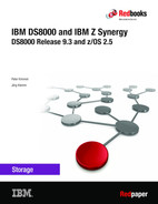
Metro Mirror (MM) is the synchronous volume replication approach that uses DS8000 firmware. The technology that is used is known as Peer-to-Peer Remote Copy (PPRC).
Figure 2-1 shows the basic sequence of operations. The goal is to ensure the safe and consistent data arrival at the receiving site of MM with the least cycles possible between both sites. MM achieves this goal quickly.

Figure 2-1 Metro Mirror basic operation
A balanced approach between pre-deposited MM writes at the receiving site, and occasional feedback from the receiving control unit (CU) back to the sending CU allows the use of the Fibre Channel links and MM paths between both sites as efficiently as possible.
Before Release 9.2, in an MM full-duplex scenario, the auxiliary storage was not directly accessed for reads, even though it was physically closer to the host. In Figure 2-1 on page 8, if IBM HyperSwap® was used, the host stops reading from H1, and all read I/O are done from H2 after it is made the primary storage.
The same situation occurs when a full duplex with an active-active configuration is used. Figure 2-2 shows the I/O process before a HyperSwap in a traditional environment. The host at site 2 reads data from H1 after it becomes the primary storage.

Figure 2-2 Metro Mirror without Consistent Read from Secondary
When HyperSwap is done from primary to the auxiliary storage on site 2, the host server at site 1 sends all read I/Os to the primary storage, which is now the H2 on site 2. Now, all the reads are at a distance from the site 1 host perspective, as shown in Figure 2-3.

Figure 2-3 Metro Mirror after HyperSwap without Consistent Read from Secondary
With Release 9.2, IBM introduced Consistent Read from Secondary (CRS), which allows applications reads to run through the auxiliary storage server and avoid extra overhead that is caused by the distance between the host server and the primary storage, as shown in Figure 2-4.
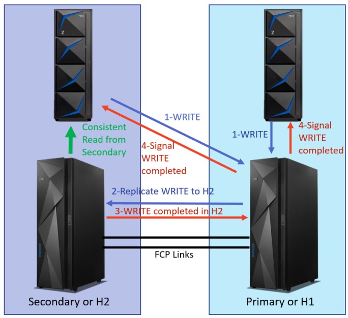
Figure 2-4 Metro Mirror after HyperSwap with Consistent Read from Secondary
For more information about CRS, see 2.3, “Consistent Read from Secondary” on page 20.
2.1.2 Global Mirror 2-site asynchronous volume replication
IBM offers a software-based solution to provide a replication technology that can bridge any distance and still ensure consistent data at the remote site. The solution is known as Global Mirror (GM). The goal is to provide an asynchronous replication technology that can run in an autonomic fashion and provide data currency (within no more than 5 seconds) at a distant site.
The data consistency at a distant site is ensured for a single storage server pair and across as many as 16 storage systems. This consistency is made possible without other constraints, such as imposing timestamps on each write I/O.
The basic operational sequence of GM is shown in Figure 2-5.

Figure 2-5 Global Mirror basic operation managed out of the storage system
From a host perspective, the write I/O behaves as though it is writing to a nonmirrored volume. The host receives an I/O completion event when the write data arrives in the cache and nonvolatile cache portion of the DS8000 cache. Then, the DS8000 storage system asynchronously replicates the data and sends it to the remote site. The replication I/O is completed when the data is secured in the remote cache and remote non-volatile cache.
GM combines the Global Copy and FlashCopy functions. Global Copy performs the data replication, and FlashCopy secures the previous data from H2 onto J2 before the respective track on H2 is overwritten by the replication I/O. Therefore, J2 behaves as a journal for H2.
The GM consistency group creation process is solely performed within the DS8000 storage systems. Synergy comes into play when managing such a configuration through IBM Copy Services Manager (CSM) or IBM Geographically Dispersed Parallel Sysplex (GDPS).
2.1.3 z/OS Global Mirror 2-site asynchronous volume replication
|
Important: The IBM DS8900F family is the last platform to support z/OS Global Mirror. New z/OS Global Mirror functions are not provided with IBM DS8900F. For more information, see IBM Announcement Letter 920-001.
|
IBM zGM essentially is z/OS software-based asynchronous volume replication. The design goal for IBM zGM was to not exceed 5 seconds in remaining current with the primary site.
IBM zGM relies on timestamped ECKD write I/Os for each write I/O to each IBM zGM primary Count Key Data (CKD) volume. IBM zGM can manage only CKD volumes.
IBM zGM relies on timestamped ECKD write I/Os for each write I/O to each IBM zGM primary Count Key Data (CKD) volume. IBM zGM can manage only CKD volumes.
The basic components of IBM zGM operations are shown in Figure 2-6.

Figure 2-6 IBM zGM basic operation that is managed through IBM Z software
Figure 2-6 shows how closely IBM Z software cooperates with the DS8000 storage system:
1. Application write I/Os perform at the same speed as with writing to an unmirrored volume in H1. Each write I/O also contains a unique timestamp. The IBM Parallel Sysplex® Timer clock is used.
2. Immediately after successfully storing the data to cache and nonvolatile cache storage in the DS8000 storage system, the I/O is complete from an application perspective.
3. System Data Mover (SDM) is a highly parallel working driver that fetches the data from the H1 site as fast as possible by using particular enhancements in z/OS and its Input/Output Supervisor (IOS). Any bandwidth between sites can be used by the SDM and its multiple-reader support.
4. SDM internally sorts all write I/Os according to the applied timestamp during application write I/O processing to ensure the same write order to the secondary volumes as they occurred to the primary volumes.
5. To resume operations after an unplanned outage of any component within the remote site, SDM applies first the consistency groups onto a journal. Next, SDM writes the same consistency group (or groups) to the secondary volumes and then frees the corresponding journal space.
After IBM zGM reaches a balanced system level (combining all involved components), it is a firm solution that runs unnoticed. The key requirement is to provide enough bandwidth between sites and on the storage backend at the recovery site to manage the amount of write data arriving at the local site.
2.1.4 Metro/Global Mirror 3-site solution
Metro/Global Mirror (MGM) is solely based on the DS8000 firmware. It is a cascaded approach that spans over three sites.
The first leg is an MM relationship from site 1 to site 2. Then, the journey continues to a potentially distant site 3 with GM. The role of the site 2 volumes is a cascaded status. The same volume in site 2 is an MM secondary volume in a DUPLEX state while being a Global Copy primary volume with a PENDING status.
The basic components of an MGM configuration are shown in Figure 2-7.
Figure 2-7 Metro/Global Mirror cascaded 3-site solution
Often, site 1 and site 2 are in a campus or metropolitan area within MM acceptable distances. In a typical IBM Z environment, both sites are usually at a distance that is also supported by the Parallel Sysplex architecture and spread the IBM Z server across site 1 and site 2.
Both sites might be only a few kilometers apart from each other to allow an efficient data-sharing approach within the coupling facility. MM acceptable distances are often measured from approximately 100 meters (328 feet) to approximately 5 - 6 km (3.10 - 3.72 miles) because the synergy of this configuration relies on Parallel Sysplex functions and MM in combination with HyperSwap.
When coupling facility-based data sharing is not a potential issue, the distance can be as much as the supported distance by the Parallel Sysplex Timer, which is up to 100 km (62.13 miles) between site 1 and site 2. Then, another synergy item plays a significant role.
When a HyperSwap occurs, and application writes run from site 1 application servers to the
site 2 storage systems, the High-Performance FICON for IBM Z (zHPF) Extended Distance (ED) II support improves the performance of large write I/Os.
site 2 storage systems, the High-Performance FICON for IBM Z (zHPF) Extended Distance (ED) II support improves the performance of large write I/Os.
Site 1 and site 2 fulfill the role of DR covering site 1 and site 2 and HA when site 1 components fail or the storage server (or servers) experience any type of outage. Site 3 is a pure DR site when site 1 and site 2 are no longer available.
|
Important: A management framework, such as CSM or GDPS, is required to manage a 3- or 4-site volume replication configuration.
|
2.1.5 Multiple-Target Peer-to-Peer Remote Copy 3-site solutions
Multiple-Target Peer-to-Peer Remote Copy (MT-PPRC) was available since DS8870 firmware levels 7.4 or later. It is also a 3-site Copy Services configuration.
It is called MT-PPRC because it can have two Copy Services relationships that are based on volume copies in site 2 with another relationship in site 3. These Copy Services relationships can be either of the following approaches:
•Two MM relationships of the same site 1 volume
•A combination of an MM relationship between site 1 and site 2 and a second GM or Global Copy relationship from site 1 to another site 3
Both approaches are described next.
MT-PPRC can be used to migrate data from primary or secondary DS8000 storage systems in a PPRC configuration. By using MT-PPRC, you can perform a migration procedure with little or no periods in which the system is not protected by mirroring.
MT-PPRC 3-site with two synchronous targets
The basic mode of operation and configuration of MT-PPRC with two MM relationships is shown in Figure 2-8.

Figure 2-8 MT-PPRC with two synchronous targets
With MT-PPRC and two MM relationships, the DS8000 storage system provides another level of DR and combined with HyperSwap, another level of HA.
The primary storage system schedules two parallel and synchronous replication writes to a target DS8000 storage system in site 2 and another to target DS8000 storage system in site 3. After both replication writes succeed, the application write is considered successfully completed by the host server.
Depending on the available storage area network (SAN) infrastructure, site 2 and site 3 also can be connected to potentially allow synchronous replication from site 2 to site 3 or the opposite configuration if a HyperSwap event occurs in site 1. This configuration is indicated by the HyperSwap action that is shown in Figure 2-8 and requires a Fibre Channel connection (FICON) from the IBM Z server in site 1 to site 2 or site 3.
Managing such a 3-site MT-PPRC configuration is supported by GDPS (GDPS Metro, dual-leg) or by CSM. This support is also proof of how closely IBM Z-based Copy Services software and HyperSwap interact with the connected DS8000 storage systems.
MT-PPRC 3-site configuration with a synchronous and asynchronous target
Another possible MT-PPRC configuration, which implies a Parallel Sysplex configuration across site 1 and site 2, is shown in Figure 2-9. In this configuration, the storage system in site 1 synchronously replicates disk storage volumes over MM to site 2.

Figure 2-9 MT-PPRC with synchronous and asynchronous target of H1
Although the SAN fabric configuration that is shown in Figure 2-9 also allows a cascaded configuration from site 2 to site 3, the implication here is that GM is the second Copy Services relationship from site 1 to site 3 that is running through a SAN fabric, which might have SAN switches in all three sites. This configuration allows for the highest flexibility.
You must also plan for redundancy in the SAN fabric, which is not shown in Figure 2-9.
Similar considerations apply, as shown in Figure 2-8 on page 16. HyperSwap might transfer the active site from site 1 to site 2 and carry the GM relationship from site 1 to site 2. This configuration can keep the GM relationship active and preserve DR capability in site 3 after a potential HyperSwap event.
When returning the active site to site 1 (if the storage system in site 1 is running again),
CSM supports an incremental resynch approach: from site 2 to site 1, and returning to site 1 through a planned HyperSwap operation from site 2 to site 1 when H2 and H1 are back in a FULL-DUPLEX state.
CSM supports an incremental resynch approach: from site 2 to site 1, and returning to site 1 through a planned HyperSwap operation from site 2 to site 1 when H2 and H1 are back in a FULL-DUPLEX state.
Another subsequent incremental resynch from H1 to H2, and automatically enabling HyperSwap when H1 and H2 are back in a FULL-DUPLEX state, establishes the original configuration, including returning GM back to H1 to H3/J3.
This configuration includes some potential to provide a robust HA/DR configuration.
Again, this configuration combines IBM Z server-based services (such as HyperSwap and hosting Copy Services management software) with the unique DS8000 Copy Services capabilities.
2.1.6 Symmetrical HA/DR 4-site solutions
Many customers conduct regular failover operations to DR sites to comply with regulation requirements, perform data center maintenance at primary locations, or exercise DR capabilities. In such environments, having the ability of still maintaining HA while systems are running on DR sites is a requirement.
The combination of cascading and MT-PPRC on DS8000 machines can provide 4-site solutions. Customers can have sites that span two different metropolitan areas while still maintaining HA/DR capabilities between them and independent of where their systems are running. How this solution can be accomplished is shown in Figure 2-10.

Figure 2-10 Symmetrical HADR 4-site solution
In this example, sites 1 and 2 are running a production workload on “Metropolitan Area A” while Sites 3 and 4 are a DR environment on “Metropolitan Area B”.
H1 includes an active HyperSwap capable MM relationship with H2, and H2 includes an active GM relationship with H3. H1 also features a “stand-by” GM relationship with H3 (denoted with a dotted line in Figure 2-10). In this case, if H2 encounters any issues, the GM relationship can be taken over by H1 without needing full synchronization to H3. H3 also has an active Global Copy relationship with H4, which allows H4 to be close to a “synchronized state” with H3.
If a planned or unplanned DR situation is declared, the systems can be failed over from Metropolitan Area A to Metropolitan Area B. In this case, an H3 to H4 replication relationship can be converted from Global Copy to MM, and HyperSwap can be enabled between them, which provides data HA.
When Metropolitan Area A is ready to be reactivated, H1 becomes the target site for the GM relationship and features a Global Copy relationship that is started from H1 to H2. After the four sites are synchronized, the systems can remain running on Metropolitan Area B with DR protection on Metropolitan Area A, or failed back to Metropolitan Area A, which makes Metropolitan Area B again the DR environment.
This configuration is fully supported by GDPS and CSM. For more information, see IBM GDPS: An Introduction to Concepts and Capabilities, SG24-6374.
2.2 z/OS HyperSwap
For many years, z/OS provided the capability to transparently swap the access from one device to another device. The first use of this capability for disk storage volumes occurred with PPRC dynamic address switching (P/DAS). For more information, see the following
IBM Documentation web pages:
IBM Documentation web pages:
The z/OS-based swap process that redirects I/Os from device H1 to H2 (if these devices are in an MM relationship and in the FULL DUPLEX state) is shown in Figure 2-11.

Figure 2-11 z/OS swap process
The core of this process is to exchange (swap) the content of the two unit control blocks (UCBs), which represent the disk storage devices. Among the many details they contain about a device, the UCBs also include one or more channel paths or one or more channel-path identifiers (CHPIDs) that connect to the two devices.
Figure 2-11 on page 19 also shows the status after the UCB swap operation. Before the swap, all I/O to the device on 123 (which is the MM primary device) ran through CHPID 6E.
Eventually, all I/O traffic to 123 is stopped before the swap operation occurs. After all I/O to 123 is quiesced, the swap process exchanges the UCB content of device 123 and device 456. After the swap is completed, IOS resumes I/O operations, and the UCB eventually directs the resumed I/O to CHPID BA, which connects to device 456. An earlier step of the swap process is also to change the MM status of the device on 456 from the SECONDARY DUPLEX to the PRIMARY SUSPENDED state.
IBM enhanced this swap process and raised the number of swap operations that are running in parallel. With today’s processor speeds and dedicated highly parallel running swap services within the HyperSwap address space, many thousands of swap operations can occur in a single-digit number of seconds. The key to modernizing this swap process is HyperSwap, which performs in its own address space.
In addition to the actual swap operation that the z/OS HyperSwap service provides, specific DS8000 Copy Services commands can be issued during the swap operation to trigger freeze and failover functions within the DS8000 storage system.
Also, IOS knows that HyperSwap autonomically performs a HyperSwap operation after a trigger is raised that is based on an issue to or within the primary storage server in H1.
Because this HyperSwap service is not an externalized interface, another authorized user must enable this service and work closely with this z/OS based HyperSwap service.
Currently, authorized users of HyperSwap services are CSM and GDPS. Both solutions manage Copy Services configurations and closely interact with the HyperSwap address space to provide a Copy Services configuration to HyperSwap services after the configuration is in a suitable FULL-DUPLEX state.
2.3 Consistent Read from Secondary
In a single-site workload MM configuration, the host processor and primary storage are on the same site, and the auxiliary storage is at some distance from the host processor. All read and write operations are performed locally to the primary storage, and writes are mirrored to the secondary storage.
After a HyperSwap is performed and the mirroring direction is reversed, the secondary is now closer to the processor, and the primary is at distance. With CRS, data is read from the auxiliary storage within an MM relationship as though it was the primary storage, which represents a performance improvement in a z/OS Metro Mirror environment after you shorten the distance between the host and the storage for I/O reads.
To enable consistent reads, z/OS must issue a request to start a consistent read management (CRM) session between the primary and auxiliary storage systems for each participating logical subsystem (LSS).
The CRM session maintains a heartbeat between the primary and auxiliary storage systems. While the secondary receives a heartbeat from the primary within a pre-determined time interval, read operations are allowed to the secondary. If the heartbeat is not received, reads are disallowed from the secondary until the heartbeat is resumed.
CRM becomes active for an LSS when the first system issues a request to start CRM. Subsequent start requests by other systems are ignored.
CRM is stopped only if a PPRC suspension occurs, a specific request is issued to stop CRM, or the HyperSwap configuration is purged.
CRS requirements
This section describes the z/OS requirements to enable CRS:
•The primary and auxiliary storage systems must support CRS. This support is achieved by using DS8900 with microode 9.2 or later.
•The MM relationship is in duplex state, and a HyperSwap configuration is loaded.
•The auxiliary storage system is closer to the processor than the primary. This situation is evaluated on a system-by-system basis.
•z/OS 2.3 or later. APARs OA61131, OA61170, OA61171, and OA61172 are required.
•z/OS has started CRM for the LSS, that is, the heartbeats are transferred between the primary and auxiliary storage.
•The CRS function is enabled in the software.
•A new READSEC keyword on IECIOSxx parmlib or SETIOS command:
ZHPFOPTS,MAXSIZE={nnnn|SYSTEM},READSEC={YES|NO}
– YES: Enables CRS for the current system.
– NO: Disables CRS for the current system.
•zHPF is enabled for the primary and secondary devices.
2.4 Copy Services Manager and HyperSwap
IBM CSM is required to use HyperSwap within z/OS for an MM configuration. This section does not describe CSM beyond the fact that it manages sessions. Such a session contains all MM volume pairs that are set up and defined within a Parallel Sysplex configuration. From a user perspective, the entity of management is the session only.
CSM is server-based and includes two interfaces: a GUI and a command-line interface (CLI). The CSM server is preinstalled on the DS8900F Hardware Management Console (HMC). It also can run on all common server platforms, such as IBM AIX®, Linux, Microsoft Windows, and on z/OS within the UNIX System Services or UNIX System Services shell.
CSM can handle all z/OS-based CKD volumes within its MM session, even when the CSM server is hosted on the HMC or a distributed server. However, a best practice is to use the robust IBM Z server platform and place the CSM server in a z/OS logical partition (LPAR). Also, when possible, you can host the CSM stand-by server in another z/OS LPAR at the other site.
Figure 2-11 on page 19 shows that CSM appears unavailable because CSM is not necessary when z/OS performs an IBM HyperSwap operation. This fact is also true when HyperSwap is enabled within a Parallel Sysplex configuration. Therefore, CSM is also unavailable, as shown in Figure 2-12.

Figure 2-12 HyperSwap enabled: CSM is passive
As shown in Figure 2-12, HyperSwap is represented in an LPAR by the following address spaces:
•The HyperSwap application programming interface (HSIBAPI) address space that handles the swap process.
•The HyperSwap Management (HSIB) address space that is the communication handler for its peers in other Parallel Sysplex members.
Figure 2-12 also shows normal operations with the active I/O paths that are connected to H1 volumes, which are connected through MM to H2 and all in a correctly working FULL-DUPLEX state. This requirement must be met to reach the HyperSwap enabled state.
You can also query the HyperSwap status by using the z/OS display command, as shown in Example 2-1.
Example 2-1 Querying the HyperSwap status by using a z/OS system command
D HS,STATUS
IOSHM0303I HyperSwap Status 671
Replication Session: MGM
HyperSwap enabled
New member configuration load failed: Disable
Planned swap recovery: Disable
Unplanned swap recovery: Partition
FreezeAll: Yes
Stop: No
Example 2-2 shows another z/OS system command that can be used to control HyperSwap and disable or enable HyperSwap when a HyperSwap session exists. Because only one potential HyperSwap session is allowed within a Parallel Sysplex, referring to a specific name in the SETHS z/OS system command is not necessary.
Example 2-2 z/OS system commands to disable or enable HyperSwap
RO *ALL,SETHS DISABLE
RO *ALL,SETHS ENABLE
However, it might be necessary to disable HyperSwap in a planned fashion to avoid a HyperSwap operation during a controlled and planned activity that might trigger a HyperSwap operation. After such a controlled activity, the HyperSwap can be reenabled so that z/OS HyperSwap regains control.
Example 2-3 shows another z/OS system command that can be used to query a complete HyperSwap configuration. However, that command might not be helpful when thousands of MM volume pairs are within the HyperSwap session.
Example 2-3 Querying the complete HyperSwap configuration
D HS,CONFIG(DETAIL,ALL)
IOSHM0304I HyperSwap Configuration 495
Replication Session: MGM
Prim. SSID UA DEV# VOLSER Sec. SSID UA DEV# Status
A0 31 0A031 A#A031 40 31 04031
A0 7F 0A07F A#A07F 40 7F 0407F
A0 AF 0A0AF A#A0AF 40 AF 040AF
A0 72 0A072 A#A072 40 72 04072
A0 A2 0A0A2 A#A0A2 40 A2 040A2
A0 13 0A013 A#A013 40 13 04013
. . . . . . . . . . . . . . . .
To see why a HyperSwap session is unavailable, a basic approach is to start with another D HS z/OS system command, as shown in Example 2-4.
Example 2-4 Querying HyperSwap for exceptions
D HS,CONFIG(EXCEPTION,ALL)
IOSHM0304I HyperSwap Configuration 840
Replication Session: MGM
None Duplex
2.4.1 HyperSwap to site H2
A healthy and enabled HyperSwap session is shown in Figure 2-12 on page 22. However, for planned or unplanned reasons, a HyperSwap trigger can change the configuration to what is shown in Figure 2-13.

Figure 2-13 After HyperSwap: CSM is still passive
After a planned or unplanned HyperSwap switched the active volumes from H1 to H2, CSM remains passive and not involved. HyperSwap eventually notifies CSM about the session state change after the HyperSwap operation is completed.
During the actual swap operation, HyperSwap is also responsible for issuing all the necessary Copy Services commands to perform the complete failover to H2. This failover also leads to the MM state change of the H2 volumes from secondary DUPLEX to primary SUSPENDED.
2.4.2 Returning to site H1
After the decision is made to return the active site to H1 and if the DS8000 storage system in H1 is recovered and still holds all the data at a level when the HyperSwap occurred, CSM is required to perform the necessary steps.
The first steps to return the active site to H1 are shown in Figure 2-14.

Figure 2-14 Reestablishing Metro Mirror and returning to H1: CSM required
When H2 was the active site, all relevant updates to the H2 configuration were logged within the DS8000 storage system and the corresponding bitmap.
You must return to the corresponding CSM session. There, you discover that the session changed and is no longer in a green OK status.
To start the process and to return the active volumes to H1, complete the following steps:
1. Modify the CSM session to allow the volumes to be replicated in the opposite direction that it was using. This action enables the session to replicate from H2 to H1.
2. Start the replication to resynchronize the volumes incrementally from H2 to H1 by using a CSM START_H2_H1 command.
After the incremental resynchronization process is completed for all volumes within the session and everything is back to DUPLEX, CSM returns the configuration to HyperSwap, which then switches back to enable the session for HyperSwap ready.
To return the active volumes back to H1, complete the following steps:
1. Issue a planned HyperSwap through the CSM or by using the SETHS SWAP z/OS system command. Again, this command performs a swap operation and puts the active volumes back to H1, including the MM status of primary SUSPENDED.
2. CSM performs the following actions as before:
a. Allows the session to replicate from H1 to H2.
b. Resynchronizes all the volume pairs from H1 to H2 through another START_H1_H2 command.
After all MM pairs are in the FULL-DUPLEX state, CSM again signals the new configuration to HyperSwap, enabling HyperSwap ready, and the replication continues now from H1 to H2.
2.4.3 Summary
CSM follows the high IBM standards that also apply for the enhancements that are made to IBM Z and the DS8000 storage system.
CSM is the enabler for z/OS and its HyperSwap function. This synergy allows a 2-, 3-, or 4-site MM-based disk volume configuration to achieve high standards in data availability and DR readiness in a fully transparent fashion to the application I/Os.
2.5 Geographically Dispersed Parallel Sysplex
GDPS is a solution that manages complex multisite HA-DR IBM Z environments. GDPS simplifies DS8000 storage system replication and Parallel Sysplex management while providing end-to-end application business resilience.
To address an entire site failure, GDPS can perform a site switch to another local site or to a remote (out-of-region) location that is based on predefined, automated scripts. Various GDPS offerings are available (see Figure 2-15), and each one addresses specific HADR goals that can be customized to meet various recovery point objective (RPO) and recovery time objective (RTO) requirements.

Figure 2-15 GDPS offerings
One difference between options is the type of DS8000 Copy Services that is used as a building block for HADR design. The following Copy Services are used:
•GDPS Metro HyperSwap Manager (GDPS HM) and GDPS Metro (the former GDPS/PPRC): Based on DS8000 synchronous data replication MM (known as PPRC).
•GDPS Global - GM (GDPS GM): Based on the DS8000 GM, which is an asynchronous form of remote copy.
•GDPS Global - Extended Remote Copy (GDPS XRC): Uses asynchronous data replication XRC (also known as IBM zGM).
•GDPS Metro Global - GM (GDPS MGM): Uses MM and GM disk replication for a 3-site or 4-site HADR environment.
•GDPS Metro (dual-leg): Supports Multi-Target Metro Mirror (MTMM) on DS8000 storage systems. GDPS Metro dual-leg provides similar capabilities as the available capabilities in GDPS Metro single-leg while extending PPRC management and HyperSwap capabilities to cover the two replication legs.
•GDPS Metro Global - XRC (GDPS MzGM): Uses MM and XRC or IBM zGM disk replication for a 3-site or 4-site HADR environment.
•GDPS Continuous Availability (GDPS AA): A multisite HADR solution at almost unlimited distances. This solution is based on software-based asynchronous mirroring between two active production sysplexes that are running the same applications with the ability to process workloads in either site.
For more information about GDPS and each option, see IBM GDPS: An Introduction to Concepts and Capabilities, SG24-6374.
2.5.1 GDPS and DS8000 synergy features
Almost all GDPS solutions (except for GDPS AA) rely on IBM disk replication technologies that are used in the DS8000 storage family. This section provides more information about the key DS8000 technologies that GDPS supports and uses.
Metro Mirror (PPRC) failover/failback support
When a primary disk failure occurs and the disks are switched to the secondary devices, failover/failback support eliminates the need to perform a full copy when reestablishing replication in the opposite direction. Because the primary and secondary volumes are often in the same state when the freeze occurred, the only differences between the volumes are the updates that occur to the secondary devices after the switch.
Failover processing sets the secondary devices to primary suspended status and starts change-recording for any subsequent changes that are made. When the mirror is reestablished with failback processing, the original primary devices become secondary devices, and changed tracks are resynchronized.
GDPS Metro transparently uses the failover/failback capability. This support mitigates RTO exposures by reducing the amount of time that is needed to resynchronize mirroring after a HyperSwap. The resynchronization time depends on how long the mirroring was suspended and the number of changed tracks that must be transferred.
If an entire central processor complex (CPC) fails, GDPS can run the CECFAIL_cpcname recovery script, which can contain any valid statements, such as CAPACITY statements. This script can be used to schedule the capacity changes that needed on the backup CPCs.
GDPS also supports MTMM on the IBM DS8900F, DS8880, and DS8870 storage systems. Initial support is for two synchronous copies from a single primary volume, also known as an MTMM configuration. GDPS Metro (dual-leg) provides similar capabilities to the ones that are available in single-leg GDPS Metro while extending PPRC management and HyperSwap capabilities to cover the two replication legs.
Global Copy
Global Copy (initially known as PPRC-XD) is an asynchronous form of the DS8000 advanced copy functions. GDPS uses Global Copy rather than synchronous MM (PPRC) to reduce the performance effect of certain remote copy operations that potentially involve a large amount of data. The replication links are typically sized for steady-state update activity, but not for bulk synchronous replication, such as initial volume copy or resynchronization.
Initial copy or resynchronizations by using synchronous copy do not need to be performed because the secondary disks cannot be made consistent until all disks in the configuration reach the duplex state. Therefore, GDPS supports initial copy and resynchronization by using asynchronous Global Copy.
When GDPS starts copy operations in asynchronous copy mode, GDPS monitors the progress of the copy operation. When the volumes are near full duplex state, GDPS converts the replication from the asynchronous copy mode to synchronous. Initial copy or resynchronization by using Global Copy eliminates the performance effect of synchronous mirroring on production workloads.
The use of asynchronous copy allows clients to establish or resynchronize mirroring during periods of high production workload. It also might reduce the time during which the configuration is exposed.
DS8000 Health Message Alert
An unplanned HyperSwap is started automatically by GDPS if a primary disk failure occurs.
In addition to a disk problem being detected as a result of an I/O operation, a primary disk subsystem can proactively report that it is experiencing an acute problem. The DS8000 storage system features a special microcode function that is known as the Storage Controller Health Message Alert capability. It alerts z/OS when hardware events occur and generates a message and Event Notification Facility (ENF) signal, as shown in Example 2-5.
Example 2-5 DS8000 Health Message Alert
IEA074I STORAGE CONTROLLER HEALTH,MC=20,TOKEN=1004,SSID=AB01, DEVICE NED=2107.961.IBM.75.0000000ABCD1.0100,PPRC SECONDARY CONTROLLER RECOVERY ACTION
The DS8000 storage system reports problems of different severities. Those problems that are classified as acute are also treated as HyperSwap triggers. After systems are swapped to use the secondary disks, the disk subsystem and operating system can attempt to perform recovery actions on the former primary without affecting the applications that use those disks.
One main benefit of the Health Message Alert function is to reduce false freeze events. GDPS Freeze and Conditional Stop actions query the secondary disk subsystem to determine whether systems can be allowed to continue in a freeze event.
Metro Mirror (PPRC) suspension
An MM suspension generates a message aggregation that is also known as Summary Event Notification. This aggregation dramatically reduces host interrupts and operator messages when an MM volume pair is suspended.
When GDPS performs a freeze, all primary devices in the MM configuration suspend. This suspension can result in significant state change interrupt (SCI) traffic and many messages in all systems. GDPS supports reporting suspensions in a summary message per DS8000 logical control unit (LCU) instead of at the individual device level.
When compared to reporting suspensions on a per devices basis, the Summary Event Notification dramatically reduces the message traffic and extraneous processing that is associated with MM suspension events and freeze processing. Examples exist where 10,000 operator messages were reduced to under 200.
Soft Fence feature
After a GDPS HyperSwap or an unplanned site switch, potential exposures exist to systems that are connected to the original primary MM (PPRC) volumes. Figure 2-16 shows that after a planned or unplanned HyperSwap, the GDPS changes the secondary volumes to primary suspended, but the former primary volumes’ statuses remain unchanged. Therefore, these devices remain accessible and usable to any system within or outside the sysplex. In this case, possibilities exist to update or perform an IPL accidentally from the wrong set of disks, which can result in potential data integrity or a data loss problem.

Figure 2-16 GDPS and DS8000 Soft Fence feature
GDPS uses a DS8000 capability that is called Soft Fence to fence (block access to a selected device). GDPS uses Soft Fence when suitable to fence devices that otherwise might be exposed to accidental update; for example, after a GDPS HyperSwap event, as shown in Figure 2-16.
Although GDPS includes built-in protection features that prevent an IPL of the systems from the incorrect set of disks, the DS8000 Soft Fence function is more protection. If an IPL of any system is done manually (without GDPS), the attempt of an IPL from the wrong set of disks (fenced former primary MM volumes) is prohibited.
Also, other systems that are outside the sysplex (and therefore outside GDPS control) can access the former primary MM volumes. Soft Fence protection blocks any attempt to update these volumes.
On-Demand Dump
When problems occur with disk systems, such as problems that result in an unplanned HyperSwap, a mirroring suspension, performance issues, or a lack of diagnostic data from the time that the event occurs, can result in difficulties in identifying the root cause of the problem. Taking a full statesave can lead to temporary disruption to host I/O.
The On-Demand Dump (ODD) capability of the DS8000 storage system facilitates taking a nondisruptive statesave (NDSS) at the time such an event occurs. The DS8000 microcode performs this statesave automatically for specific events, such as generating a memory dump of the primary disk system that triggers a freeze event and allows an NDSS to be requested by a user. This feature enables first-failure data capture (FFDC) and ensures that diagnostic data can help with problem determination efforts.
GDPS supports taking an NDSS that uses the remote copy pages (or web GUI). In addition to this support, GDPS autonomically takes an NDSS if an unplanned freeze or HyperSwap event occurs.
Query Host Access
When an MM (PPRC) disk pair is being established, the target (secondary) device must not be used by any system. The same is true when establishing a FlashCopy relationship with a target device. If the target is in use, the establishment of the PPRC or FlashCopy relationship fails.
When such failures occur, identifying which system is delaying the operation can be a tedious task. The DS8000 Query Host Access function provides the means to query and identify which system uses a selected device. This function is used by the IBM Device Support Facilities (ICKDSF) utility (for more information, see 4.5, “Volume formatting overwrite protection” on page 55) and by GDPS.
GDPS features the following capabilities:
•Query Host Access identifies the LPAR by using the selected device through the CPU serial number and LPAR number. For the operations staff to convert this information to a system or CPU and LPAR name is still a tedious job. GDPS performs this conversion and presents the operator with more readily usable information, which avoids this extra conversion effort.
•When GDPS is requested to perform a PPRC or FlashCopy establish operation, GDPS first performs Query Host Access to determine whether the operation is expected to succeed or fail as a result of one or more target devices being in use. GDPS alerts the operator if the operation is expected to fail and identifies the target devices in use and the LPARs holding them.
•GDPS continually monitors the target devices that are defined in the GDPS configuration and alerts operations that target devices are in use when they should not be in use. This alert allows operations to fix the reported problems in a timely manner.
•With GDPS, the operator can perform ad hoc Query Host Access to any selected device by using the GDPS pages (or GUI).
The GDPS QHA monitor was optimized with GDPS V4.4 to significantly reduce the time that is taken to query each CPC that is defined in the System Automation policy.
IBM DS8000 Easy Tier Heat Map Transfer
IBM DS8000 Easy Tier Heat Map Transfer (HMT) can transfer the Easy Tier learning from an MM (PPRC) primary to the secondary disk system. The secondary disk system can also be optimized based on this learning and have similar performance characteristics in the HyperSwap event. For more information, see 5.6, “Easy Tier” on page 92.
GDPS integrates support for HMT. The suitable HMT actions (such as the starting and stopping of processing and reversing transfer direction) are incorporated into the GDPS managed processes. For example, if MM is temporarily suspended by GDPS for a planned or unplanned secondary disk outage, HMT is also suspended. If the MM direction is reversed as a result of a HyperSwap, the HMT direction is also reversed.
GDPS HMT support was integrated with the running of GDPS MGM procedures to ensure that the transfer direction of Easy Tier learning information reflects the replication direction at the successful completion of the procedure. With GDPS V3.12 and later, HMT is supported for all available GDPS options (2-, 3-, and 4-site environments).
Logical Corruption Protection
GDPS Logical Corruption Protection (LCP) is a set of GDPS capabilities that is provided in response to the growing number of requests for a GDPS managed Continuous Data Protection capability. It is aimed at helping customers to recover from logical corruption events, whether caused by internal attacks or cyberattacks.
LCP can capture multiple, secure point-in-time copies of critical production data and restore the data to production. LCP also can recover a specific point-in-time copy to another set of devices that can be used to start one or more isolated recovery systems to analyze the scope of a specific logical corruption event. The protection copies can be captured by using the Safeguarded Copy technology or the FlashCopy technology.
Support is introduced for multiple recovery copy sets, which provides greater flexibility when GDPS LCP Manager is used. Starting with GDPS V4.1, the LCP feature of GDPS Metro enables the capture of multiple and secure point-in-time copies that can later be used for identification, repair, or replacement of production data that was compromised by cyberattacks or internal attacks, or corrupted by system failures or human error. Up to 10 recovery copy sets can be defined for use. The total of FlashCopy sets and recovery copy sets cannot exceed 11.
With GDPS V4.3, the LCP Manager is extended to support the DS8000 Safeguarded Copy function. Profile characteristics can be defined, such as the retention period before the capture is classed as expired or the minimum interval between captures, which prevents flooding the storage with bad captures after a corruption event.
GDPS V4.4 instructs DS8000 to create and maintain a persistent Safeguarded Copy recovery relationship so that the user can query the persistent Safeguarded Copy recovery relationship and percentage that is copied through the GDPS LCP Manager interface.
For more information about Safeguarded Copy, see IBM DS8000 Safeguarded Copy (Updated for DS8000 R9.2.1), REDP-5506.
For more information how IBM DS8000® Storage with Safeguarded Copy is integrated in the IBM Z Cyber Vault solution, see Getting Started with IBM Z Cyber Vault, SG24-8511.
2.5.2 GDPS and DS8000 synergy summary
GDPS is designed for complex multi-site or single-site IBM Z environments. It can manage disk remote copy, automate Parallel Sysplex operation tasks, and perform failure recovery from a single point of control easily and efficiently. Continuous collaboration over many years between IBM Z, GDPS, and DS8000 development teams delivered a robust HA-DR design that is commonly used among IBM Z clients.
With its HyperSwap capability, GDPS is the ideal solution when targeting 99.99999% (seven nines) availability.
Moreover, it also allows clients to run DR tests more frequently without affecting production. The more that you practice your DR process, the more confident you become in recovering your systems and applications if a real disaster strikes.
..................Content has been hidden....................
You can't read the all page of ebook, please click here login for view all page.