

VMware and IBM Spectrum Virtualize multi-site guidelines
The term disaster recovery (DR) is normally used regarding a large, significant, and disruptive event, such as an earthquake or flood. But DR can also be valuable for smaller events, such as power-loss or a localized network failure.
Companies prepare for DR by implementing business continuity solutions to maintain and restore operations if a disruption or disaster occurs, but they do not always test those solutions regularly. The ability to recover the systems needs to be tested regularly to make sure that procedures work, rather than waiting until a disruption happens. Flaws might be detected each time you test because perfection is impossible to achieve when the environment changes every day.
Copy services are a collection of functions that provide capabilities for business continuity, disaster recovery, data migration, and data duplication solutions. This chapter provides an overview and the preferred best practices guide for VMware and IBM Spectrum Virtualize for copy services capabilities. These capabilities include FlashCopy, Metro Mirror, Global Mirror, and VMware Site Recovery Manager.
This chapter describes some of the solutions that can help you prepare your environment to recover from a disruption and includes the following sections:
5.1 Copy Services overview
IBM Spectrum Virtualize storage system offers a complete set of copy services functions to VMware that provide capabilities for business continuity, disaster recovery, data movement, and data duplication solutions. The IBM Spectrum Virtualize Family Storage Replication Adapter (SRA) is a software add-on that integrates with the VMware Site Recovery Manager (SRM) solution and enables SRM to perform failovers together with supported IBM FlashSystem Storage. You can make mirror images of part or all of your data between two sites, which is advantageous in DR scenarios with the capabilities of copying data from production environments to another site for resilience.
The following copy services (relationships) are supported by IBM Spectrum Virtualize storage system:
•FlashCopy, for point-in-time copy
•Metro Mirror, for synchronous remote copy
•Global Mirror, for asynchronous remote copy
•Global Mirror with Change Volumes (GMCV), for asynchronous remote copy for a low-bandwidth connection
Replication relationships can be created between a maximum of four independent
IBM Spectrum Virtualize storage systems. Partnerships can be a mix of any of the IBM Spectrum Virtualize systems. For example, an IBM FlashSystem storage array replicating to a SAN Volume Controller (SVC) storage system and vice versa. For more information about these services, see Chapter 10, “Advanced Copy Services” in the IBM Redbooks publication titledImplementing IBM FlashSystem with IBM Spectrum Virtualize V8.4, SG24-8492.
IBM Spectrum Virtualize storage systems. Partnerships can be a mix of any of the IBM Spectrum Virtualize systems. For example, an IBM FlashSystem storage array replicating to a SAN Volume Controller (SVC) storage system and vice versa. For more information about these services, see Chapter 10, “Advanced Copy Services” in the IBM Redbooks publication titledImplementing IBM FlashSystem with IBM Spectrum Virtualize V8.4, SG24-8492.
|
Note: All these services are supported by VMware SRM when using IBM Spectrum Virtualize Family SRA.
|
5.1.1 FlashCopy
FlashCopy is known as a point-in-time copy. It makes a copy of the blocks from a source volume and duplicates them to the target volumes.
When you initiate a FlashCopy operation, a FlashCopy relationship is created between a source volume and a target volume. A FlashCopy relationship is a mapping of the FlashCopy source volume and a FlashCopy target volume. This mapping allows a point-in-time copy of that source volume to be copied to the associated target volume. If it is a persistent FlashCopy, the FlashCopy relationship exists between this volume pair from the time that you initiate a FlashCopy operation until the storage unit copies all data from the source volume to the target volume, or you delete the FlashCopy relationship.
5.1.2 Metro Mirror
Metro Mirror is a type of remote copying that creates a synchronous copy of data from a primary volume to a secondary volume that is read-only. A secondary volume can be located either on the same system or on another system. The maximum distance that is allowed between systems in Metro Mirror relationships is 300 km. When a host issues a write command to a volume, the data is replicated to the remote cluster before the host is notified that the I/O completed.
|
Tip: Metro Mirror can impact write latency. For best performance, use shorter distances and create Metro Mirror relationships only between systems with similar performance.
|
5.1.3 Global Mirror
The Global Mirror function provides an asynchronous copy process. When a host writes to the primary volume, confirmation of I/O completion is received before the write operation completes for the copy on the secondary volume. The maximum acceptable distance between systems in Global Mirror relationships is 25.000 km or 250 ms latency.
Global Mirror change volumes
Global Mirror change volumes are copies of data from a primary volume or secondary volume that are used in Global Mirror relationships. Using change volumes lowers bandwidth requirements by addressing only the average throughput, not the peak.
5.1.4 Remote copy consistency groups
You can group Metro Mirror or Global Mirror relationships into a consistency group so that they can be updated at the same time. A command is then simultaneously applied to all of the relationships in the consistency group.
5.1.5 VMware Site Recovery Manager
VMware SRM is well known in the virtualization world for providing simple, affordable, and reliable business continuity and disaster recovery management.
Using SRM with IBM Spectrum Virtualize storage system can help you protect your virtual environment.
SRM automates the failover processes and the ability to test failover processes or DR without having a negative impact on the live environment, which helps you meet your recovery time objectives (RTOs).
VMware SRM supports two forms of replication:
•Array-based replication (ABR), where the storage system manages the virtual machine (VM) replication with the following attributes:
– Compatible storage is required, such as systems powered by IBM Spectrum Virtualize.
– Storage arrays are configured with a SRA.
•Host-based replication, which is known as vSphere Replication (VR), where the Elastic Sky X integrated (ESXi) manages the VM replication with the following attributes:
– Does not depend on storage array compatibility.
– Increased network efficiency by replicating only the most recent data in the changed disk areas.
– Minimum RPO = 5 minutes.
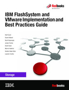
Figure 5-1 shows an overview of the VMware SRM.
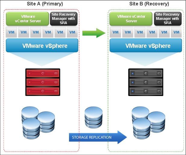
Figure 5-1 VMware SRM
VMware SRM requires one vCenter server in each site with the respective licenses. Also, if you are using SRM with IBM FlashSystem storage, you are required to use an IBM Spectrum Virtualize SRA, which is described in 5.1.6, “Storage Replication Adapter” on page 108.
For more information about SRM, see the VMware Site Recovery Manager Documentation.
5.1.6 Storage Replication Adapter
SRA is a storage vendor plug-in that is developed by IBM. SRA is required for the correct functioning of SRM when it is used with IBM Spectrum Virtualize storage systems.
The adapter is used to enable the management of Advanced Copy Services (ACS) on
IBM FlashSystem Storage, such as Metro Mirror and Global Mirror (including changed volumes).
IBM FlashSystem Storage, such as Metro Mirror and Global Mirror (including changed volumes).
The combination of SRM and SRA enables the automated failover of VMs from one location to another, connected by either Metro Mirror or Global Mirror technology.
By using the IBM Spectrum Virtualize Family Storage Replication Adapter, VMware administrators can automate the failover of an IBM FlashSystem 9200 at the primary SRM site to a compatible system, such as another IBM FlashSystem 9200, 7200, or IBM SAN Volume Controller at a recovery (secondary) SRM site.
In a failover, the ESXi servers at the secondary SRM site mount the replicated data stores on the mirrored volumes of the auxiliary storage system. When the primary site is back online, perform fallback from the recovery site to the primary site by clicking Reprotect in the SRM.
For more information, see the IBM Spectrum Virtualize Family Storage Replication Adapter documentation.
5.2 Storage Replication Adapter with VMware Site Recovery Manager
Figure 5-2 shows how an IBM Spectrum Virtualize storage system is integrated in a typical VMware SRM DR solution.

Figure 5-2 SRA and VMware SRM with IBM Spectrum Virtualize integrated solution
SRA configuration might vary depending on the specific site configuration. Consider the following preparatory steps and configuration when using SRA with SRM.
5.2.1 Storage replication adapter planning
This section describes storage replication adapter planning.
Preparing the SRA environment
To prepare the SRA environment, complete the following steps:
1. Ensure that the supported storage systems firmware version is used.
2. Provision appropriate-sized target volumes on the storage system at the recovery (secondary) site. Create Metro or Global-Mirror relationships between the source and target volumes and add the relationships to consistency groups, as needed.
3. Create a dedicated user on both source and target storage systems with the right privileges for the SRA:
– For SRA non-preconfigured settings, a user with Administrator or higher privilege is needed.
– For SRA preconfigured settings, a user with CopyOperator or higher privilege is needed.
4. Use the same username and password on both the protected (primary) and the recovery site.
Verifying the mirroring configuration
Consider the following points for verifying the mirroring configuration:
•Ensure that all VMware Elastic Sky X (ESX) hosts, IBM Spectrum Virtualize storage systems, and volumes at both sites are properly connected to their remote counterparts and configured for site mirroring.
•Establish mirror-connectivity between the local IBM Spectrum Virtualize storage system at the protected (primary) site and the IBM Spectrum Virtualize storage system at the recovery (secondary) site. For IBM Stretched Cluster when using SVC, stretched volumes are created, and both copies of a stretched volume are online. For IBM HyperSwap, HyperSwap volumes are created, and both the primary volume and secondary volume of a HyperSwap volume are online.
•Use a unique name for each IBM Spectrum Virtualize storage system at both the protected and the recovery sites.
•Make sure that the storage pools that contain the replicated volumes at both sites have sufficient available capacity for creating the snapshots of all replicated volumes concurrently.
•For non pre-configured environments, an extra space for Test Failover and Failover is necessary. Ensure that enough space is available in the pool.
•Ensure that protected volumes are mapped to the protected VMware ESX hosts:
– For Stretched Cluster, the stretched volumes are mapped to both the protected and recovery VMware ESX hosts.
– For IBM HyperSwap, the primary volume of a HyperSwap is mapped to both the protected and recovery VMware ESX hosts.
•Ensure that remote copy relationships exist for all volumes:
– For IBM Stretched Cluster, stretched volumes are created, and both copies of a stretched volume are online.
– For IBM HyperSwap, HyperSwap volumes are created, and both the primary volume and secondary volume of a HyperSwap volume are online.
•Ensure that for non-preconfigured environments, the recovery volumes remain unmapped.
•Make sure that the recovery VMware ESX or ESXi hosts are defined as hosts at the recovery site and report as online.
Verifying the VMware Site Recovery Manager installation
Before you embark with the installation of IBM Spectrum Virtualize storage system SRA container, verify that the VMware SRM is already installed and accessible at both protected (primary) site and the recovery (secondary) site by following these steps:
1. Log in to the VMware vSphere Web Client (Figure 5-3).

Figure 5-3 VMware vSphere Web Client login
2. Go to the vSphere Client window and verify that the Site Recovery icon is displayed (Figure 5-4).

Figure 5-4 VMware vSphere Web Client home page
5.2.2 Storage Replication Adapter for VMware installation
For more information about how to download IBM Spectrum Virtualize Family Storage Replication Adapter for VMware, see Downloading the SRA.
As a best practice, stop your currently installed version of the SRA container before running a different version. Ensure that you satisfy all of the prerequisites that are listed in before you run the SRA container. Follow the below steps to run the IBM Spectrum Virtualize storage system SRA container on the SRM server.
|
Note: The IBM Spectrum Virtualize Family SRA installation creates a shortcut that is named IBM Spectrum Virtualize Family SRA Configuration Utility.exe on the desktop. The configuration utility must be run on both the protected (primary) site and the recovery (secondary) site SRM host.
|
1. Log in to the VMware SRM Appliance Management interface as admin, as shown in Figure 5-5 on page 113.
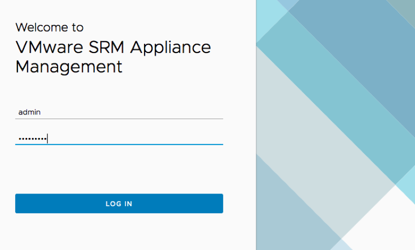
Figure 5-5 SRM Appliance Management interface login
2. In the SRM Appliance Management interface, select Storage Replication Adapters → NEW ADAPTER (Figure 5-6).
Figure 5-6 SRM Appliance Management interface
3. Click Upload. Go to the directory where you saved the SRA file, and double-click it. The SRA upload process begins.
4. When the upload process finishes, click Close. The SRA card is displayed on the Storage Replication Adapters view (Figure 5-7).

Figure 5-7 Storage Replication Adapters view
5. Log in to the vSphere Web Client.
6. Select Site Recovery → Open Site Recovery, select a site pair, and click View Details.
7. On the Site Pair tab, select Configure → Array Based Replication → Storage Replication Adapters → RESCAN ADAPTERS. After the rescan is complete, the Status field value is updated to OK (Figure 5-8 on page 115).

Figure 5-8 Site Recovery view
5.2.3 Storage Replication Adapter configuration and usage guide
When the storage replication adapter installation is complete, see Configuration.
Account for the following practices when working with SRA and VMware ARM:
•Create Metro or Global Mirror relationships between the source and target VDisks and add them to consistency groups, as explained in “Preparing the SRA environment” on page 110.
•Before you use the SRA, make sure that the Metro or Global Mirror relationships and consistency groups are in a consistent synchronized state.
•For Stretched Cluster, make sure that the two copies of a stretched volume are at different sites and that both copies are online.
•For IBM HyperSwap, make sure that the primary volume and secondary volume of a HyperSwap volume are online.
•Consider the following tips when you add an Array-air to the VMware SRM are as follows:
– Enter the same Common Information Model Object Manager (CIMOM) address and Common Information Model (CIM) port as the primary IBM Spectrum Virtualize Cluster, if you are using IBM Stretched Cluster or IBM HyperSwap.
– If M:N topology is being used, enter any one of the IBM Spectrum Virtualize Clusters (N) on the remote site for the CIM address of the remote IBM Spectrum Virtualize Cluster. The term M:N refers to the number of IBM Spectrum Virtualize Clusters on the local site (M) and remote site (N). Calculations are not derived from this term. M:N is used only to denote the replication process.
– IBM Spectrum Virtualize multiple-port configuration is supported by SRA when 1:1 IBM Spectrum Virtualize topology is used. With IBM Spectrum Virtualize M:N topology and multiple-port configuration, replication might not work because SRA communicates with IBM Spectrum Virtualize PORT 1.
For more information, see Adding an array pair to the VMware Site Recovery Manager.
•All volumes that participate in SRM and belong to the same remote copy consistency group are shown under a single local consistency group. To avoid data inconsistencies when adding replicated VDisks to the same VM or data store, all VDisks used by a single VM or application must be added to the same consistency group.
If you plan to use VMware SRM to manage replicated volumes, use the Name Filter by using prefixes for the volume name. The volume names can be different for each site, but prefixes must be paired with the remote site array manager. For example, if the local site volume name is Win2019, and on the remote site it is mapped to Rec_Win2019, then you could enter the prefix Pri in the Name Filter field for the local site and the prefix Rec on the remote site. To use the Name Filter for the consistency group, enter the same names and prefixes at both the local and remote sites. For more information, see Filtering volumes and consistency groups by name.
•Consider the following items for managing data stores and consistency groups:
– The data stores of one VM should be in the same consistency group.
– The data store of the VM and the raw disk in the VM should be in the same consistency group.
– You must have administrator privileges to install the SRM.
– Set the appropriate timeout and rescan values in SRM for the recovery of many VMs.
5.3 IBM HyperSwap with VMware vSphere Metro Storage Cluster
The IBM Spectrum Virtualize storage system supports multiple VMware vSphere stretched-storage cluster solutions with HyperSwap to provide the following benefits:
•Highly available active-active vSphere data stores
•Workload mobility
•Cross-site automated load-balancing
•Enhanced downtime avoidance
•Disaster avoidance
In this document, the focus is on solutions that rely both on VMware vSphere Metro Storage Cluster (vMSC) and VMware SRM in relation to IBM Spectrum Virtualize.
5.3.1 IBM HyperSwap
IBM Spectrum Virtualize HyperSwap is a dual-site solution that provides continuous availability of data during planned and unplanned outages. If storage at either site goes offline, HyperSwap automatically fails over storage access to the system at the surviving site.
When you configure a system with a HyperSwap topology, the system is split between two sites for data recovery, migration, or high availability use cases. When a HyperSwap topology is configured, each node or enclosure, external storage system, and host in the system configuration must be assigned to one of the sites in the topology. Both node canisters of an I/O group must be at the same site. This site must be the same site of any external storage systems that provide the managed disks to that I/O group. When managed disks are added to storage pools, their site attributes must match. This requirement ensures that each copy in a HyperSwap volume is fully independent and spans multiple failure domains (Figure 5-9).

Figure 5-9 IBM HyperSwap
HyperSwap Volume is a group of volumes and remote copy relationship all working together to provide the active-active solution, and ensure that data is synchronized between sites.
A single HyperSwap Volume consists of the following items:
•A Master Volume and a Master Change Volume (CV) in one system site
•An Auxiliary Volume and an Auxiliary CV in the other system site
An active-active HyperSwap relationship exists between the Master and Auxiliary volumes to facilitate the data synchronization and replication between sites.
However, when you create a HyperSwap volume, the necessary components are created automatically, and the HyperSwap Volume can be managed as a single object.
Like a traditional Metro Mirror relationship, the active-active relationship attempts to keep the Master Volume and Auxiliary Volume synchronized while also servicing application I/O requests. The relationship uses the CVs as journaling volumes during the resynchronization process (Figure 5-10).
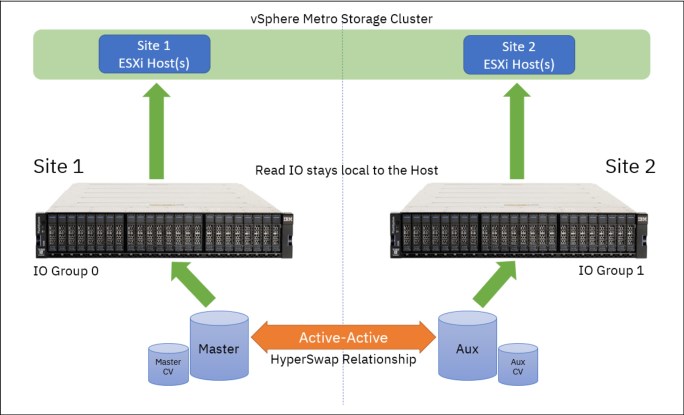
Figure 5-10 Read operations from hosts on either site are serviced by the local I/O group
The HyperSwap Volume always uses the unique identifier (UID) of the Master Volume. The HyperSwap Volume is assigned to the host by mapping only the Master Volume even though access to the Auxiliary Volume is ensured by the HyperSwap function. For each HyperSwap volume, hosts across both sites see a single volume that is presented from the storage system with the UID of the Master Volume.
To preserve application consistency when spanning multiple volumes, Consistency Groups can be created to keep a group of HyperSwap volumes consistent.
Cluster considerations
Consider the following tips when you work with HyperSwap and VMware vSphere Metro Storage Cluster (vMSC):
• One IBM Spectrum Virtualize-based storage system, which consists of at least two I/O groups. Each I/O group is at a different site. Both nodes of an I/O group are at the same site.
• HyperSwap-protected hosts on IBM Spectrum Virtualize must be connected to both storage nodes by using Internet Small Computer System Interface (iSCSI) or Fibre Channel.
• In addition to the two sites that are defined as failure domain, a third site is needed to house a quorum disk or IP quorum application.
• More system resources are used to support a fully independent cache on each site. This allows full performance even if one site is lost.
HyperSwap relationships
One site is considered as the Primary for each HyperSwap Volume or Consistency Group. This site is dynamically chosen according to the site that writes more data (more than 75% of write I/Os) to the volume or consistency group over a 20-minute period.
This role can change as follows:
•After a period of 20 minutes, if an I/O majority is detected in nodes on the non-Primary site
•Immediately, if a Primary-site outage occurs
|
Note: Low write-throughput rates do not trigger a direction switch to protect against unnecessary direction changes when experiencing a trivial workload.
|
While the I/O group on each site processes all reads from the hosts on that local site, any write requests must be replicated across the inter-site link, which incurs added latency. Writes to the primary site experience a latency of 1x the round-trip time (RTT) between the sites, however due to the initial forwarding process, writes to the non-primary site will experience 2x the round-trip time. This additional performance overhead should be considered when you provision storage for latency-sensitive applications.
These relationships automatically run and switch direction according to which copy or copies are online and up-to-date.
Relationships can be grouped into consistency groups, in the same way as other types of remote-copy relationships. The consistency groups fail over consistently as a group based on the state of all copies in the group. An image that can be used for disaster recovery is maintained at each site.
HyperSwap I/O flow
This section contains examples of the HyperSwap I/O flow. In the examples below, Site 1 is considered as Primary.
Read operations from ESXi Hosts at either site
Figure 5-11 illustrates the flow of read I/O requests from hosts at either site in the VMware vSphere Metro Storage Cluster.

Figure 5-11 Write operations from hosts on either site are serviced by the local I/O group
Read I/O is facilitated by whichever I/O group is local to the requesting host, which prevents the I/O from having to transfer the long-distance link and incurring unnecessary latency.
Write operations from ESXi hosts at local site
When hosts write on the Primary site, and the host, node, controller, or managed disk (MDisk) site awareness is correctly configured, the write I/Os go straight to the Primary site volume and I/O Group. The write I/Os are then replicated to the Secondary site volume and I/O Group (Figure 5-12 on page 121).
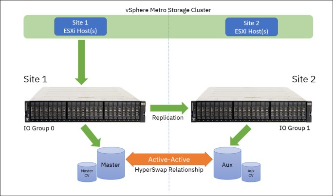
Figure 5-12 Write operations from hosts on primary are replicated
Write operations from ESXi hosts at remote site
In this scenario, a write to I/O Group 1 needs to be applied to both copies, but the replication code cannot handle that task on I/O Group 0 (because I/O Group 0 currently holds the Primary copy). The write data is initially transferred from the host into a data buffer on a node in I/O Group 1. The node in I/O Group 1 sends the write, both metadata and customer data, to a node in I/O Group 0 (Figure 5-13).

Figure 5-13 Write operations from hosts on Secondary are forwarded and replicated
On the node in I/O Group 0, the write is handled as though it were written directly to that I/O Group by a host. The replication code applies the write to the I/O Group 0 cache, and replicates it to I/O Group 1 to apply to the cache there, which means that writes to the secondary site have increased latency and use more bandwidth between the sites. However, sustained writes mainly to the secondary site over a 20-minute period will switch the direction of the HyperSwap relationship, which eliminates this impact.
|
Note: Whenever the direction of a HyperSwap relationship changes, there is a brief pause to all I/O requests to that volume. In most situations, this pause is less than 1 second. Where possible, consider how application workload to a single HyperSwap volume (or HyperSwap consistency group) across sites can reduce the likelihood of repeated direction changes.
|
5.3.2 VMware vSphere Metro Storage Cluster
VMware vMSC is a unique storage-related feature and configuration that combines replication with array-based clustering that allows a single cluster to operate across geographically separate data centers. This capability allows two separated data centers to operate as a single cluster that provides significant benefits when maintaining data availability during both planned and unplanned downtimes.
IBM Spectrum Virtualize facilitates vMSC with the ability to create single storage cluster that spans both sites, such that a data store must be accessible in both locations. In other words, the data store must be able to read and be written to simultaneously from both sites by using the HyperSwap feature of IBM Spectrum Virtualize. In a failure, the vSphere hosts are able to continue read and write access to the data store from either location seamlessly and with no impact on ongoing storage operations.
Uniform versus Non-Uniform vMSC configurations
There are two ways in which a vMSC can be configured. The following terms refer to the different configurations of host connectivity across sites:
•Non-Uniform host access configuration is where an ESXi host has storage connectivity to only the storage system local to that site.
•Uniform host access configuration is where an ESXi host has storage connectivity to both local and remote storage systems.
For every volume presented from the IBM FlashSystem, a preferred node is automatically elected. To evenly distribute the workload across the IBM FlashSystem upon volume creation, the preferred node usually alternates between each node in the I/O group.
When you map a volume to a host object and rescan the host bus adapter (HBA) on the ESXi host, ESXi automatically identifies the available paths to both nodes in the I/O group, as follows:
•The paths to the preferred node for each volume are identified as the “Active/Optimized paths”.
•The paths to the non-preferred node are identified as “Active/Non-Optimized paths”.
By default, ESXi uses the Round-Robin path selection policy (PSP) to distribute I/O as follows:
•Over any available “Active/Optimized paths” to the preferred node.
•Only fail over to “Active/Non-Optimized paths” if available paths to the preferred node do not exist.
Non-Uniform configuration
In Non-Uniform vMSC implementations, ESXi hosts use Small Computer System Interface (SCSI) Asymmetric Logical Unit Access (ALUA) states to identify Active/Optimized paths to the preferred node in the local I/O group and Active/Non-Optimized paths to the partner node. The host has no visibility of the storage system at the remote site (Figure 5-14).

Figure 5-14 Non-Uniform host access vMSC
With Non-Uniform vMSC environments, if a storage failure occurs at the local site, the ESXi hosts lose access to the storage because paths are not available to the storage system at the remote site. However, this architecture might be useful when you run clustered applications like Microsoft SQL or Microsoft Exchange with servers that are located at each site. It might be preferable to have a clustered application fail over so that an application can continue to run with locally available storage.
Uniform configuration
In Uniform vMSC implementation, ESXi hosts also uses SCSI ALUA states to identify Active/Optimized paths to the preferred node and Active/Non-Optimized paths to the partner node in the local I/O group. Extra paths to the remote I/O group are automatically detected as “Active/Non-Optimized”. ESXi uses the Optimized paths to the local preferred node where possible, and only fail over to the Non-Optimized paths if there are no available paths to the preferred node (Figure 5-15).
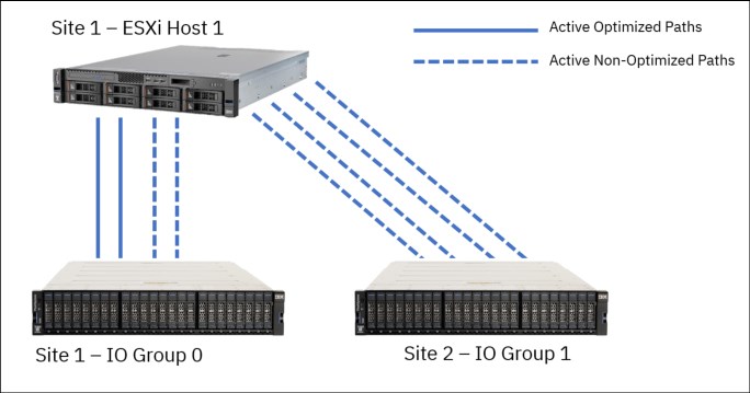
Figure 5-15 Uniform host access vMSC
5.3.3 IBM HyperSwap with VMware vSphere Metro Storage
Given the performance characteristics of a HyperSwap topology, it might be beneficial to review how HyperSwap volumes can be used by ESXi hosts to ensure optimal performance, data continuity, and reliability.
Virtual Machine File System data store provisioning
As shown in Figure 5-16 on page 125, the following three different data store architectures can be considered when provisioning and consuming Virtual Machine File System (VMFS) data stores in a HyperSwap vMSC environment:
•Traditional Disaster Recovery
•Mixed access
•Alternating access
Each of these models applies at a single data store level. Therefore, it is possible to incorporate all three methods in an IBM FlashSystem HyperSwap architecture.
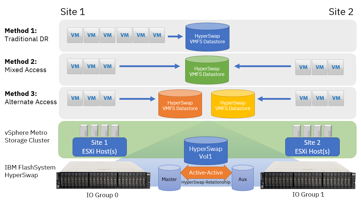
Figure 5-16 Three data store architectures
Method 1: Traditional Disaster Recovery
This model can be conceptualized as a traditional DR configuration. In normal operating conditions, all VMs are running from a single site, and only failover to ESXi hosts at the remote site in a system or storage outage at Site 1. In this scenario, the direction of the HyperSwap relationship for the VMFS data store is static because I/O is not running at Site 2. In a site outage, all the VMs are powered up on the ESXi hosts at Site 2 without requiring intervention on the storage system to enable access to the volumes.
The negative aspect of this configuration is that there can be many ESXi servers and storage resource at Site 2 that are idle.
Method 2: Mixed Access
In this scenario, the number of VMs for a data store is split between both sites. ESXi servers at both sites are used, which maximizes compute resource at both sites. However, as discussed in “HyperSwap I/O flow” on page 119, any writes being performed at the non-primary site incur more latency when traversing the inter-site link. Potentially half of the vSphere infrastructure can then be exposed to extra, unnecessary latency overhead.
In addition, if the workload is unregulated, the direction of the HyperSwap relationship can be swapped repeatedly, which generates more I/O pauses for each change of direction.
Method 3: Alternative Access
This scenario requires a minor additional management overhead to provision storage and maintain the vSphere environment. However, this scenario likely enables optimal storage performance and maximum realization of available compute resource.
Consider creating multiple VMFS data stores where the primary associated site alternates between Site 1 and Site 2, and keep VM-storage resources local to hosts that are running the VMs.
An example configuration is as follows:
•When creating data stores, use odd-numbered data stores to have a site preference of Site 1, and even-numbered data stores designated to Site 2.
•Migrate the compute resource for half of the VMs over to ESXi hosts on Site 2 to create an even distribution of workload between the two sites.
•For VMs running on ESXi hosts at Site 1, ensure the VMDKs are provisioned on odd-numbered data stores.
For VMs running on ESXi hosts at Site 2, ensure the VMDKs are provisioned on the even-numbered data stores.
•Create Host/VM Groups and Host/VM Rules in vSphere to ensure that Distributed Resource Scheduler (DRS) can function correctly to redistribute VMs across hosts within a site if required, but still enable failover in an outage.
As detailed in “Write operations from ESXi hosts at remote site” on page 121, Alternative Access Method ensures that instead of any write I/Os at either site having to be forwarded over the inter-site link before being replicated to the remote site, they will be serviced by the I/O group at the site where the I/O originated. This method reduces the overall latency and increases the performance and throughput.
The intention is for a given HyperSwap volume or consistency group to keep VM I/O workloads local to the host running the VM, which minimizes the workloads being driven from a host at the non-primary site.
In a site outage at either site, vSphere high availability (HA) automatically recover the VMs on the surviving site.
For more information about DRS Host/VM groups and rules, see Create a Host DRS Group.
VMware Distributed Resource Scheduler
VMware DRS capabilities bring efficiency in the management of workloads through grouping VMware ESXi hosts into resource clusters to separate computing requests to different sites or failure domain. Employing VMware DRS in an active-active storage solution (such as HyperSwap) provides highly available resources to your workloads.
In an ideal HyperSwap environment, you do not want VMs to move to the other site. Rather, you want VMs to move to the other site only in a site failure, or intentionally to balance workloads and achieve optimal performance.
ESX hostnames
Create a logical naming convention that allows you to quickly identify which site a host is in. For example, the site can be included in the chosen naming convention or you can choose a numbering system that reflects the location (for example odd hosts are in site one). The naming convention makes the designing and the day-to-to running of your system easier.
Data locality and host affinity rules
Ideally, hosts should access data from their local storage array to improve response time. To ensure that this situation is the case, use VMware affinity rules to define the preferred site for VMs to run from a local logical unit number (LUN).
Logically name the LUNs with their home sites
This task is not a must and some might argue that they want the flexibility to move LUNs between data centers, but it makes it easier for business as usual (BAU) staff to track which are local data stores.
VMware vSphere host multipathing ensures that VMs that are running continue to operate during various failure scenarios. Table 5-1 outlines the tested and supported failure scenarios when using SVC or IBM FlashSystem Family HyperSwap function, and VMware vSphere Metro Storage Cluster (vMSC).
Table 5-1 IBM Spectrum Virtualize HyperSwap and VMware vSphere Metro Storage Cluster supported failure scenarios
|
Failure scenario
|
HyperSwap behavior
|
VMware HA impact
|
|
Path failure: SVC or IBM FlashSystem Family Back-End (BE) Port
|
Single path failure between SVC or IBM FlashSystem Family control enclosure and flash enclosure. No impact on HyperSwap.
|
No impact.
|
|
Path failure: SVC or IBM FlashSystem Family Front-End (FE) Port
|
Single path failure between SVC or IBM FlashSystem Family control enclosure and vSphere host. vSphere host uses alternative paths.
|
No impact.
|
|
BE flash enclosure failure at Site-1
|
SVC or IBM FlashSystem Family continues to operate from the volume copy at Site-2. When the flash enclosure at Site-1 is available, HyperSwap synchronizes the copies.
|
No impact.
|
|
BE flash enclosure failure at Site-2
|
Same behavior as failure at Site-1.
|
No impact.
|
|
SVC or IBM FlashSystem Family control enclosure failure
|
SVC or IBM FlashSystem Family continues to provide access to all volumes through the other control enclosures.
|
No impact.
|
|
Complete Site-1 failure (The failure includes all vSphere hosts and SVC or IBM FlashSystem Family controllers at Site-1)
|
SVC or IBM FlashSystem Family continues to provide access to all volumes through the control enclosures at Site 2. When the control enclosures at Site-1 are restored, the volume copies are synchronized.
|
VMs running on vSphere hosts at the failed site are impacted. VMware HA automatically restarts them on vSphere hosts at Site-2.
|
|
Complete site 2 failure
|
Same behavior as a failure of Site-1.
|
Same behavior as a failure of Site-1.
|
|
Multiple vSphere host failures Power Off
|
No impact.
|
VMware HA automatically restarts the VMs on available ESXi hosts in the VMware HA cluster.
|
|
Multiple vSphere host failures, network disconnect
|
No impact.
|
VMware HA continues to use the data store heartbeat to exchange cluster heartbeats. No impact.
|
|
SVC or IBM FlashSystem Family inter-site link failure, vSphere cluster management network failure
|
SVC or IBM FlashSystem Family active quorum is used to prevent a split-brain scenario by coordinating one I/O group to remain servicing I/O to the volumes. The other I/O group goes offline.
|
vSphere hosts continue to access volumes through the remaining I/O group. No impact.
|
|
Active SVC or IBM FlashSystem Family quorum disk failure
|
No impact to volume access. A secondary quorum disk is assigned upon failure of the active quorum.
|
No impact.
|
|
vSphere host isolation
|
No impact.
|
HA event dependent upon isolation response rules configured for the vSphere cluster. VMs can be left running, or rules can dictate for VMs to shut down and restart on other hosts in the cluster.
|
|
vCenter server failure
|
No impact.
|
No impact to running VMs or VMware HA. VMware DRS function is affected until vCenter access is restored.
|
..................Content has been hidden....................
You can't read the all page of ebook, please click here login for view all page.