


IBM Platform High Performance Computing implementation scenario
Implementing IBM Platform high performance computing (HPC) can be easily accomplished, and the process is described in this chapter. To better describe its implementation, you can find a case study (scenario) that implements the most common features when a cluster is built with IBM Platform HPC. The aim of this scenario is to guide you through the key building blocks of a complex HPC cluster that is built by using the IBM Platform HPC suite. Even if you are not using all of the components that are described in this chapter, it is worth reading it completely as the chapter brings a broader view of building a cluster and can help you build your own solution.
This chapter is not intended to replace the installation or administration manuals, but to give you a guideline of how to install and manage a cluster with the IBM Platform HPC from the residency team perspective. If you do not find all of the steps to install the cluster, see the product’s installation manuals (for more information, see “Related publications” on page 183).
The objective of this scenario focuses on a high availability implementation for the IBM Platform HPC (pHPC) with GPFS. Every section starts with a description of the concepts that are used and continues with practical examples. For example, in the next sections we describe the following tasks:
•Installing pHPC and other software, such as GPFS and ISV application.
•Provisioning GPFS server nodes and compute nodes.
This chapter includes the following topics:
|
Note: In this book, we interchange the terms IBM Platform HPC and pHPC.
|
3.1 Application Ready Solution versus scenario-based implementation
IBM has several bundled offers for IBM Platform HPC, which are named Application Ready Solutions. These bundles are most commonly represented by specific IBM hardware (Flex System, NeXtScale, and System x), a specific version of IBM Platform HPC, and an ISV application (or applications), such as Abaqus, ANSYS, Accelrys, InfoSphere BigInsights, CLC bio, Gaussian, mpiBLAST, MSC Software, and Schlumberger.
If you purchase an Application Ready Solution, everything is delivered, including the hardware and a .tar archive file with all of the requirements to automatically install your cluster, along with all the customizable scripts. For example, if you purchase GPFS for your cluster, you receive in this bundle all of the scripts to automatically provision the GPFS cluster.
IBM Application Ready Solution provides an expertly designed, tightly integrated, and performance-optimized architecture for technical computing applications. These bundles are targeted mostly for domain experts, which require technical or HPC clusters that can be quickly deployed without extensive computer skills.
This document is not intended to overlap with the Application Ready Solutions guide. Instead, it is intended to be a more generic guide. The idea is to give you an overview of how to install IBM Platform HPC.
3.2 Scenario-based implementation
In building this scenario, we consider the following key aspects of an HPC cluster and the applications that are running on it:
•The application is highly I/O intensive and requires high throughput.
•The application needs low latency communication between cluster nodes.
•There is a need for high availability of the cluster components.
•All cluster components need monitoring.
Because of these aspects, our cluster uses the following components:
•A low latency network, such as InfiniBand.
•A high-performance parallel file system, such as GPFS.
•IBM Platform LSF for workload management.
•IBM Platform Cluster Manager for high availability.
In the next sections, we describe the scenario that we build. We start by installing the management node of the cluster (single head), continue with the GPFS servers installation and configuration, followed by compute nodes provisioning with all of the necessary software installed, including pHPC software stack and the GPFS client software.
Figure 3-1 shows the components of the cluster we build in this chapter.

Figure 3-1 Cluster components
All of the software that is installed on the compute nodes is packed as distribution kits. Later in this section, we describe how to build your own kits. Moreover, if your cluster workload management requirements increases over time and you need more advanced Platform LSF features, we show you how to upgrade to the Platform LSF Enterprise Edition (for more information, see “Upgrading Platform LSF” on page 128).
Starting with version 4.1.1.1, IBM Platform HPC supports high availability for the management nodes. To show you this feature while showing the sample scenario, we reconfigure the initial cluster to provide high availability by adding a secondary management node.
Figure 3-2 shows the architecture of the cluster we build, the roles that are assigned to each node, and how they are wired together. We have two management nodes (49 and 50) that are installed with pHPC in high availability configuration, two nodes that act as GPFS server nodes, which are Network Shared Disk (NSD) servers, and the rest of the nodes are used as compute nodes. The GPFS servers can have local disks, SAS-attached, or Fiber Channel-attached disks that are shared with its clients over InfiniBand.

Figure 3-2 Cluster architecture
3.2.1 Cluster hardware
The cluster is built on 16 IBM iDataPlex nodes, which are all placed in the same rack. They are a subset of nodes that are borrowed from a larger cluster, which has 64 nodes. For easy tracking, we do not change their names. Therefore, our cluster node names are in a range i04n[49 - 64].
|
Note: There is no integration with any clusters that are installed on nodes i04n[1 - 48].
|
Each iDataPlex server in the cluster is equipped with 2 x CPU (6 cores each), 24 GB RAM, two 1-Gb Ethernet ports and one InfiniBand adapter. The two 1-Gb ports are connected to Ethernet switches for provisioning, out-of-band management, or for public network access (access to management nodes). Later in this chapter, we describe the meaning of each of these networks types. For low latency communication at the application level and for the GPFS file system, the servers are equipped with one port InfiniBand adapter that is connected to a dedicated InfiniBand switch.
In the next section, we describe each component of the cluster, their role and functionalities, along with best practices for a smooth integration into the cluster.
3.2.2 Management nodes
The management nodes play many important roles in the cluster, but the most important roles are the provisioning and the software lifecycle management functions (updates, reinstall, uninstall) of the compute nodes. Starting with version 4.1, IBM Platform HPC uses xCAT as the provisioning engine. To accomplish the provisioning function, IBM Platform HPC provides to the cluster the following suite of services:
•DHCP: The management node listens on the defined provisioning interface and answers to DHCP requests from the compute nodes.
•TFTP: Serves the PXE boot file in early stages of the boot over the network.
•DNS: If you do not have an external DNS server, you can define one on the management node.
•NFS: The management node can export local directories to be mounted on compute nodes. For example, the compute nodes can mount these exports as /home for users or /data for application data.
•HTTP: Used to share the yum repositories for operating systems or kit distributions to the compute nodes for initial installation or later updates.
•NTP: The management node can act as a time server of the cluster. If you decide not to use it as an NTP server, you can set an external NTP server.
In addition to the provisioning functions, the management node acts as a repository, which stores files and scripts for provisioning compute nodes. The repository can store the following files:
•Kickstart files
•Network boot files (PXE)
•Operating system (OS) installation files and application kits
•Postinstallation and post-boot scripts
At the same time, the management node can act as a web portal to submit, manage, and monitor jobs in the cluster, and runs services for workload management (Platform LSF). Additionally, it performs cluster monitoring of different components, such as Platform LSF (monitoring agent), hardware monitoring services (metric collection, aggregation, alerting, purging), and GPFS monitoring.
The management node also can act as a firewall to shield the cluster from external (public) networks.
3.2.3 Compute nodes
The compute nodes run workload as assigned by the workload manager (Platform LSF). Everything happens on these nodes and is a result of an action that is triggered from the management node (pHPC) or workload-manager node (Platform LSF). In our scenario, the cluster management and workload manager functions overlap on the first two nodes.
Compute node provisioning is the process of installing the operating system and related software on a compute node, sometimes with the initial software configuration. For provisioning to occur, the compute node must boot over the network (PXE).
The following provisioning types of compute nodes are available:
•Stateful provisioning is a method that deploys the operating system and related software onto persistent storage (local disk, SAN disk, or iSCSI device) such that the changes that are made to the operating system are persistent across node reboots.
•Stateless provisioning deploys the operating system into memory; therefore, the changes are not persistent across reboots. This method is faster because at provisioning time, the compute node does not spend time installing all of the packages. Instead, it uses a pre-generated stateless image on the management node. This pre-generated stateless image includes the operating system and related components.
3.2.4 Networking
Ethernet switches must be prepared before they are integrated into our cluster. For this process, the spanning-tree function and multicasting must be disabled in the switch. To speed up the process of PXE booting of compute nodes, the switch should begin forwarding the packets as it receives them. To ensure this, you should enable port-fast on the switch. If your switch does not support this feature, search for the specific function (command) that changes the forwarding scheme of your switch.
If you want to monitor the switch and add it to your pHPC monitoring portal, you must enable SNMP traps on the switch.
InfiniBand networks have many similarities to a traditional Ethernet network that is based on standard (traditional) network concepts, such as layers. In addition to these similarities, there are many differences between an InfiniBand network and an Ethernet network. The main difference is that InfiniBand provides a messaging-service that can be accessed directly by the applications.
Traditional networks are considered network-centric networks because they are mostly built with the focus on underlying switches and wires. In HPC, most of the applications need low latency for interprocess communications. This is why there is the need for a more application-centric network.
Building an application-centric network can be done by removing all unnecessary layers and by offloading the I/O operations from the CPU to the host bus adapter (HBA). This application-centric theory was transformed into a network architecture called InfiniBand. Therefore, the InfiniBand network architecture was a result of trying to determine how to make application’s communication as simple, efficient, and direct as possible.
The InfiniBand network architecture provides to the applications an easy-to-use messaging-service. With the help of this messaging-service, the application can access the network directly, instead of relying on the operating system to transfer messages. Relying on the operating system to transfer the messages adds more overhead and, as a result, more latency. This latency is caused by the time that is needed for a message to pass from the application’s virtual buffer space, through the network stack, and out into the wire. At the destination, there is an identical process in a reverse order that adds even more latency. InfiniBand avoids this through a technique that is known as stack bypass.
InfiniBand provides the messaging-service by creating a channel connecting applications that must communicate. The two applications can be in disjoint physical address spaces that are hosted by different servers. The channel links virtual address space of an application to the virtual address space of its peer application. The applications that are using the messaging-service can be user space applications or kernel space application (for example, the file system).
On each of the endpoints of the channel, there is a buffer to accumulate the network traffic. Therefore, any channel has a queue (buffer) at each end, and this forms a queue pair (QP). At each end, each queue has its own send and receive queue. Because the InfiniBand architecture requires avoiding the communication through the operating system and network stacks (as shown in Figure 3-3), the applications at each end of the channel are directly connected to the QP on their own host. This direct mapping of the applications to the QPs is done through linking the virtual address space of the application with the QP. The two applications at each endpoint of the channel can access directly the virtual address space of the peer application at the other end of the channel.

Figure 3-3 InfiniBand network communication
In essence, the infiniBand architecture creates communication channels between two disjoint virtual address spaces of peer applications by using QP, which provides a mean for local application to transfer messages directly without involving the local operating system (as shown in Figure 3-3).
Having established this communication channel, there is a need to implement methods for transferring the messages between the peers. The infiniBand architecture implemented the following transfer semantics:
•Channel semantic (SEND/RECEIVE): With this transfer method, each application accesses its own buffer only. The sending application SENDs the message and the receiving application RECEIVEs the message. When the message is received, the message is pre-posted on its receive queue.
•Memory-pair semantic (RDMA READ/WRITE): This is the opposite of the previous method. In this case, the receiving side application registers a buffer in its virtual memory space and then it passes the control of that buffer to the sending side, which uses RDMA READ or RDMA WRITE operations to either read or write the data in that buffer.
For more information about infiniBand architecture, see HPC Clusters Using InfiniBand on IBM Power Systems Servers, SG24-7767.
pHPC networking
In pHPC, you mostly manage logical networks while you are performing network management. In most of the cases, the logical networks overlap the physical networks, but not in every case. For example, in our scenario we chose to build two logical networks over one physical network: provisioning and out-of-band management (BMC).
You can define the following types of logical networks in pHPC:
•The provisioning network is used to connect the management nodes to the compute nodes, usually over a Gigabit network. The cluster performs its administration and monitoring functions over this network. For example, the DHCP service from the management node listens on the interface that is associated with this logical network and answers to the requests from the compute nodes. Moreover, all the PXE boot files and installation files are served over this network.
•The out-of-band management network (BMC) is used by the management nodes for remote hardware management of the compute nodes. The operations that are run over this network include: power control (on, off, reset, and soft-off); turn LEDs on and off; get hardware event logs or inventory information; collect sensor information, such as CPU temperature and fan speed; get energy usage, and serial console access.
•The public network is used to connect management nodes to the outside world, and to give users on the corporate network access to IBM Platform HPC web portal for cluster administration or job submission.
•The application (high-speed) network is used by applications to exchange data among its tasks that are in different nodes. In some cases, it can be a data path for applications to access the shared storage (for example, GPFS over RDMA).
In pHPC, a logical network is represented as a TCP/IP subnetwork. Such a network can be instantiated by specifying its name, an IP address range, and a gateway.
During the installation phase, the pHPC installer can configure by default a maximum of three types of networks: provisioning, out-of-band (BMC), and public. At a minimum, provisioning and out-of-band (BMC) networks must be configured. If you must configure other networks (for example, public or application), but not necessarily at installation time, you can configure this later through the pHPC web interface.
IBM Platform HPC can use two methods to add nodes to the cluster: the use of a host file or the use of the discovery feature. If you decide to use both, the provisioning subnetwork is divided into two subranges, one for each method. For example, if your provisioning subnetwork is 19.168.1.0/24, the range that is used for nodes that are added to pHPC through a host file is 192.168.1.3 - 192.168.1.200. The range for nodes that are added by the discovery method are 192.168.1.200 - 192.168.1.254.
3.2.5 Cluster prerequisites
Before cluster deployment, the following prerequisites must be met:
•The primary management node must be installed by using traditional methods with a supported operating system; for example, Red Hat Enterprise Linux 6.4 (RHEL). For more information about checking whether your partitioning layout is correct, if you installed all of the necessary packages, verifying that you disabled all unnecessary services, and so on, see the “Preparing to install Platform HPC” chapter of the IBM Platform HPC Installation Guide, SC22-5380-00.
•During the installation, the pHPC installer must access an operating system media or image file (.iso) because the installer builds a first image profile (OSimage), which is used later to deploy the compute nodes with an operating system, as shown in Figure 3-4 on page 73.
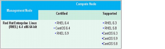
Figure 3-4 Management nodes and compute nodes operating systems
•All servers must boot over the network. You can check this by using the IBM Advanced Settings Utility (ASU) if your servers have this capability. The setting BootOrder.BootOrder contains the boot order and the value of “PXE Network” should be set ahead of any “Hard Disk” value in the ordered list. The tool can be downloaded from this website:
http://www-947.ibm.com/support/entry/portal/docdisplay?lndocid=TOOL-ASU
•All servers must have an IP address assigned to their IMM to control the BIOS/uEFI firmware remotely via the command line or the ASU. This tool can be used in later stages of your cluster deployment when you conduct performance tests because from a central point, you can tweak different parameters into the firmware to boost the cluster performance.
•To access the IBM Platform HPC web portal after installation, you need the following programs:
– Adobe Flash version 8 or higher and JRE 1.6 version or higher
– IE 8 or 9 or Firefox 21.x or higher on Windows and Firefox 10.x or higher on Linux
•For a comprehensive list of the minimal hardware and software requirements for the management nodes and compute nodes, see IBM Platform HPC Installation Guide, SC22-5380-00.
|
Note: Our cluster was built for demonstration purposes. If you plan to deploy a production cluster, make proper plans according to your environment requirements. Before you proceed with the installation, see IBM Platform HPC Installation Guide, SC22-5380-00.
|
3.2.6 Cluster deployment
Now that our cluster is defined and all the prerequisites are fulfilled, we can proceed with the cluster deployment. We start to build the cluster by installing the primary management node with the IBM Platform HPC. Before you start the installation script, remember to check all of the requirements for the management node as described in the “Preparing to install Platform HPC” chapter of IBM Platform HPC Installation Guide, SC22-5380-00.
In the following sections, you can follow the details of our cluster installation for reference, as shown in Example 3-1 on page 74.
Example 3-1 IBM Platform HPC installation
[root@i04n50 install]# ./phpc-installer.sh
Preparing to install 'phpc-installer'... [ OK ]
******************** WARNING ********************
A partial Platform HPC installation is detected.
Continuing will remove the existing installation.
Do you want to continue? (Y/N) [Y] Y
Checking for any packages [ OK ]
Cleaning database... [ OK ]
Finding the product entitlement file... [ OK ]
================================================================
Welcome to the IBM Platform HPC 4.1.1.1 Installation
================================================================
The complete IBM Platform HPC 4.1.1.1 installation includes the following:
1. License Agreement
2. Management node pre-checking
3. Specify installation settings
4. Installation
Press ENTER to continue the installation or CTRL-C to quit the installation.
================================================================
Step 1 of 4: License Agreement
================================================================
International Program License Agreement
Part 1 - General Terms
BY DOWNLOADING, INSTALLING, COPYING, ACCESSING, CLICKING ON
AN "ACCEPT" BUTTON, OR OTHERWISE USING THE PROGRAM,
LICENSEE AGREES TO THE TERMS OF THIS AGREEMENT. IF YOU ARE
ACCEPTING THESE TERMS ON BEHALF OF LICENSEE, YOU REPRESENT
AND WARRANT THAT YOU HAVE FULL AUTHORITY TO BIND LICENSEE
TO THESE TERMS. IF YOU DO NOT AGREE TO THESE TERMS,
* DO NOT DOWNLOAD, INSTALL, COPY, ACCESS, CLICK ON AN
"ACCEPT" BUTTON, OR USE THE PROGRAM; AND
* PROMPTLY RETURN THE UNUSED MEDIA, DOCUMENTATION, AND
Press Enter to continue viewing the license agreement, or
enter "1" to accept the agreement, "2" to decline it, "3"
to print it, "4" to read non-IBM terms, or "99" to go back
to the previous screen.
1
================================================================
Step 2 of 4: Management node pre-checking
================================================================
Checking hardware architecture... [ OK ]
Checking OS compatibility... [ OK ]
Checking free memory... [ OK ]
Checking if SELinux is disabled... [ OK ]
Checking if Auto Update is disabled... [ OK ]
Checking if NetworkManager is disabled... [ OK ]
Checking if PostgreSQL is disabled... [ OK ]
Checking for DNS service... [ OK ]
Checking for DHCP service... [ OK ]
Checking management node name... [ OK ]
Checking static NIC... [ OK ]
Probing DNS settings... [ OK ]
Probing language and locale settings... [ OK ]
Checking mount point for depot (/install) directory... [ OK ]
Checking required free disk space for opt directory... [ OK ]
Checking required free disk space for var directory... [ OK ]
================================================================
Step 3 of 4: Specify installation settings
================================================================
Select the installation method from the following options:
1) Quick Installation
2) Custom Installation
Enter your selection [1]: 2
The OS version must be the same as the OS version on the management node.
From the following options, select where to install the OS from:
1) CD/DVD drive
2) ISO image or mount point
Enter your selection [1]: 2
Enter the path to the first ISO image or mount point: /tmp/rhel6.4_x64.iso
Select a network interface for the provisioning network from the following options:
1) Interface: eth0, IP: 129.40.64.50, Netmask: 255.255.255.0
Enter your selection [1]: 1
Enter IP address range used for provisioning compute nodes
[129.40.64.3-129.40.64.200]: 129.40.64.51-129.40.64.92
Do you want to provision compute nodes with node discovery? (Y/N) [Y]: Y
Enter a temporary IP address range to be used for provisioning compute nodes
by node discovery. This range cannot overlap the range specified for the
provisioning compute nodes. [129.40.64.201-129.40.64.254]: 129.40.64.230-129.40.64.254
Enable a BMC network that uses the default provisioning template (Y/N) [N]: Y
Select a network to use as your BMC network
1) Create a new network
2) Provision network
Enter your selection [1]: 1
Specify a subnet for the BMC network [xxx.xxx.xxx.xxx]: 129.40.65.0
Specify a subnet mask for the BMC network [255.255.255.0]: 255.255.255.0
Specify a gateway IP address for the BMC network [None]: 129.40.65.254
Specify an IP address range for the BMC network
[129.40.65.3-129.40.65.254]: 129.40.65.51-129.40.65.92
Specify a hardware profile for the BMC network:
1) IBM_System_x_M4 IBM System x3550 M4, x3650 M4, x3750 M4
2) IBM_Flex_System_x IBM Flex System x220, x240, and x440
3) IBM_iDataPlex_M4 IBM System dx360 M4
4) IPMI Any hardware with IPMI device
5) IBM_NeXtScale_M4 IBM System nx360 M4
Enter your selection [1]: 4
Enter a domain name for the provisioning network [private.dns.zone]: pbm.ihost.com
Enter the IP addresses of extra name servers that are separated by commas
[129.40.106.1]: 129.40.106.1
Enter NTP server [pool.ntp.org]: i04mgr.pbm.ihost.com
Synchronizing management node with the time server... [ OK ]
Do you want to export the home directory on the management node
and use it for all compute nodes? (Y/N) [Y]: Y
Do you want to change the root password for compute nodes and the
default password for the Platform HPC database? (Y/N) [Y]: N
================================================================
Platform HPC Installation Summary
================================================================
You have selected the following installation settings:
Provision network domain: pbm.ihost.com
Provision network interface: eth0, 129.40.64.0/255.255.255.0
Depot (/install) directory mount point: /install
OS media: /tmp/rhel6.4_x64.iso
Network Interface: eth0
eth0 IP address range for compute nodes: 129.40.64.51-129.40.64.92
eth0 IP address range for node discovery:129.40.64.230-129.40.64.254
NTP server: i04mgr.pbm.ihost.com
Name servers: 129.40.106.1
Database administrator password: ************
Compute node root password: ************
Export home directory: Yes
Enable default BMC network with: 129.40.65.0/255.255.255.0
Default BMC network Gateway: 129.40.65.254
Default BMC network IP range: 129.40.65.51-129.40.65.92
Default BMC Hardware Profile: IPMI
================================================================
Note: To copy the OS from the OS DVD, you must insert the first
OS DVD into the DVD drive before begining the installation.
To modify any of the above settings, press "99" to go back
to "Step 3: Specify installation settings", or press "1"
to begin the installation.
1
================================================================
Step 4 of 4: Installation
================================================================
Copying Platform HPC core packages... [ OK ]
Copying Platform HPC kits... [ OK ]
Adding OS from media '/mnt3'...
* Verifying that the OS distribution, architecture,
and version are supported... [ OK ]
* Detected OS: [rhel 6 x86_64] [ OK ]
* Copying OS media. This can take a few minutes... []
Successfully added operating system. [ OK ]
Preparing the bootstrap environment... [ OK ]
Installing packages. This can take several minutes... [/]
[ OK ]
Initializing Platform HPC configuration... [-]
[ OK ]
Installing kits. This can take several minutes... [|]
[ OK ]
Running the pcmconfig script to complete the installation.
Setting up hosts/resolv files: [ OK ]
Setting up firewall: [ OK ]
Setting up dhcpd: [ OK ]
Setting up named: [ OK ]
Setting up shared NFS export: [ OK ]
Setting up ntpd: [ OK ]
Setting up LSF configuration: [ OK ]
Setting up web portal: [ OK ]
[ OK ]
Setting up Platform HPC configuration: [ OK ]
Updating management node: [ OK ]
Platform Initalization Complete
IBM System X iDataPlex dx360 M3 Server
UEFI Build Ver: 1.19 IMM Build Ver: 1.35 Diagnostics Build Ver: 9.27
2 CPU Packages Available at 6.4GT/s Link Speed [ OK ]
24576MB Memory Available at 1333MHz in Independent Channel Mode
SLOT ID LUN VENDOR PRODUCT REVISION INT13 SIZE NV
---- --- --- -------- ---------------- ---------- ----- ---------r.log.
0 1 0 IBM-ESXS VPBA146C3ETS11 N A496 Boot 136 GB
LSI Corporation MPT boot ROM successfully installed your web browser, you can access the Web Portal at http://129.40.64.50:8080.
Enter 'q' to quit or close this terminal.
source /opt/pcm/bin/pcmenv.sh
Enter 'q' to quit or close this terminal.
q
[root@i04n50 install]#
After the installation, you can connect to the web portal of your first management node by using the link at the bottom of the output of the installation script. In our case, the following link is used:
The dashboard is a panel that displays the health of your cluster (as shown in Figure 3-5 on page 78) and the resources available to your cluster (CPU and cores, RAM, and storage space) or in some cases, which resources are unavailable, by raising alarms.
Also displayed in the panel are Cluster performance metrics, such as CPU and memory load average, compute node availability over time, job slot usage, or power consumption. Spend time in this panel to get familiar with all the metrics that can help you understanding how efficiently you use your cluster resources, or if there is any issue with some components of the cluster.
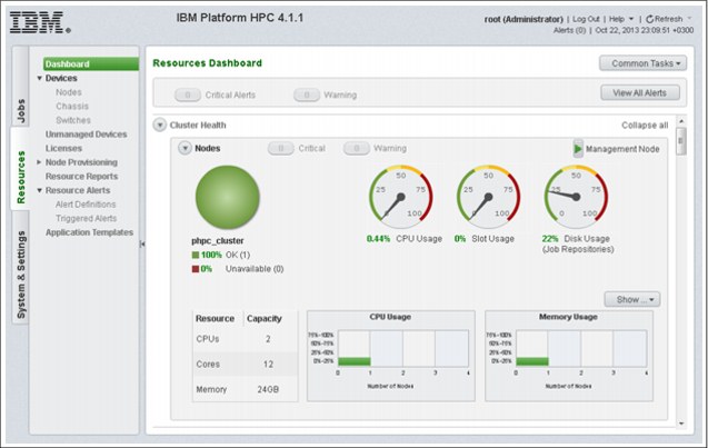
Figure 3-5 IBM Platform HPC 4.1.1 Resource Dashboard
A third main panel in this dashboard is a Rack view, which by default is provisioned with four 42U racks that can be populated with your cluster nodes or chassis. You can increase or decrease the number of the available racks, add or remove chassis, or change their position in the racks only by command line by using the commands pcmrackexport and pcmrackimport.
For example, to add a chassis into one of your racks, one option is to export the current configuration into a file by using the pcmrackexport command, adding the details of your chassis to this file, and then importing it into your cluster by using the pcmrackimport command. For more information about adding a chassis, see 3.2.7, “Provisioning cluster resources” on page 78.
The compute nodes can be provisioned into a Rack view at an unspecified or specific location. When a node is added to the cluster, if you do not specify any location, it is placed into a pool named “location unspecified”, which is outside any defined racks. Later on, you can add this node to a free location in any of the available racks by updating the node’s location through the GUI (Relocate) or the CLI.
3.2.7 Provisioning cluster resources
Now that we explored the dashboard, we start provisioning our cluster resources. The resource is a generic term that can refer to devices (compute nodes, switches, chassis), operating systems distributions, software (kits), licenses, and networks.
Devices can be of two types: managed and unmanaged.
Unmanaged devices are devices that are known by the pHPC cluster but are not provisioned, updated, or monitored by the cluster. Defining a node as unmanaged in the HPC cluster disables the node from being allocated by the provisioning engine. An example of such device can be an NAS device or NFS server, which exists in your network and exports resources to your cluster but it is not managed by pHPC.
Managed devices are devices on which the pHPC cluster can perform actions, such as provisioning, updating, monitoring, power on and off actions, inventory, and many others. There are three types of managed devices that you can define and manage: nodes, chassis, and switches.
To add node devices, you must complete some preliminary preparation tasks. For now, we add only switches and chassis devices; after all the necessary elements are defined later, we describe you how to add node devices.
Adding chassis
Adding a chassis to the cluster can be done only through the command-line interface (CLI). As a chassis is always placed into a rack, we add this device to the cluster by using rack commands. To add it, you must collect all of the parameters by which this chassis can be identified and create a chassis definition to be imported into the pHPC database. After the import finishes, you must restart the GUI interface to reflect the changes you made to the pHPC database. After the GUI restarts, you should see your chassis by clicking Devices → Chassis and under Dashboard → Rack View.
Example 3-2 shows how to add a chassis to your cluster.
Example 3-2 Add chassis to your pHPC cluster
[root@i04n50 ~]# pcmrackexport > rack.info
[root@i04n50 ~]# vi rack.info
Add your chassis definition parameters to the end of your file (rack.info). For our chassis the definition is:
chassis3:
objtype=chassis
displayname=nextscale1
height=6
ip=129.40.65.80
username=USERID
password=PASSW0RD
rack=rack1
slots=16
unit=37
urlpath=http://129.40.65.80
[root@i04n50 ~]# pcmrackimport -f rack.info
|
Note: To reflect these changes in your user interface (Dashboard), restart the GUI by running the plcclient.sh -d pcmnodeloader command.
|
For our scenario, there is no need to add a chassis because we do not have a chassis. After you add switches to your cluster definition, you can monitor and collect performance statistics by using SNMP traps.
Adding a node device
Every node you add to your cluster is unique in some aspects (MAC/IP address, name, location into the rack, and so on), and it has many similarities with other cluster nodes. For example, your cluster can be built on two different hardware types with different processing capabilities and different network adapter layout. As a consequence, you install different operating systems and applications on each node type. Therefore, you split your hardware pool in two main categories, each category having compute nodes with the same capabilities. This means that you profile the compute nodes.
For each of these profiles, you can create a template that can help provision each type of compute nodes. The provisioning template has predefined components that are determined by hardware type and network and software requirements, as shown in Figure 3-6. Further, for each of these predefined components, we use the terms hardware profile, network profile, and image profile.
|
Note: You can profile the nodes with other criteria, not only with the ones that are used for exemplification.
|

Figure 3-6 Provisioning template
As shown in Figure 3-6, each node at the end assigned an image profile, a network profile, and a hardware profile, which are part of node definition. The profiles cannot be changed without reprovisioning the node.
To add a node, it is mandatory to have all of the components (image, network, and hardware profiles) defined and functional, as shown in Figure 3-7. By default, the pHPC installer creates a few predefined profiles that are based on the information that was provided at installation time. For example, you have an image profile built that is based on an .iso image that was provided during the pHPC installation with the pHPC default kit-components, a network profile built on the networks provided (at minimum the provisioning network), and a predefined hardware profile.

Figure 3-7 Profile for adding a note
As shown in Figure 3-7, you can choose from a drop-down menu the different profiles or use the defaults. Because these profiles are common to many nodes, pHPC can create out of them a provisioning template by linking all of these profiles for later node add processes or for node provisioning. A second option is to add nodes by selecting a predefined (or user- created) provisioning template (see the submenu Select provisioning template in Figure 3-7), and not selecting each time all the component profiles. This is the default method that is used when nodes are added.
The adding nodes wizard can provision more than one node at a time. For that process, you are requested to introduce the Node name format that is used to automatically name the nodes. Nodes are managed devices represented by compute nodes, which can be added to the cluster by two methods: Discovery feature or host file (node information) method.
Adding nodes to the cluster by using the host file method allows you to add nodes with a specific host name, IP address for management, and IP address for BMC, MAC address, the position in rack, and how many units it occupies in the rack.
Now that we defined all the common components (profiles) of our nodes, we can add the details for each individual node. In the next window of the wizard, you are prompted to choose between two methods of node discovery: Auto discovery by PXE boot or import node information file.
The unique details of each node can be obtained by using one of the discovery methods. For the import node information file method, preconfigured hardware is delivered with a file that contains all of the details about each compute node (including rack details). If your hardware is not preconfigured but you know all of the details of your nodes, add them into a file and import these details by using the wizard. The file should have the format as shown in Example 3-3.
Example 3-3 Node definition example
<hostname>:
mac=<mac-address>
ip=<IP for primary NIC>
nicips=<IPs for other NICs>
rack=<rack name>
height=<server height>
unit=<server’s position in rack>
|
Note: If the NICs for the other networks (for example, bmc and eth1) are not defined in the node information file, the NICs are assigned auto-generated IP addresses. The IP address of the NIC that is associated with the BMC must be assigned accordingly on the nodes for remote power management to function correctly.
|
This method should be used when you want to assign static host names and IP addresses to your compute nodes.
The auto discovery by PXE boot method (as shown in Figure 3-8) is used most often to add nodes to the cluster when you do not know the details of your compute nodes and the name and IP address that your compute node is assigned is not important. However, you can control the name and IP address assignment by powering on the nodes individually in the order that you want. Your nodes have names and IP addressed that are assigned in a sequential order.
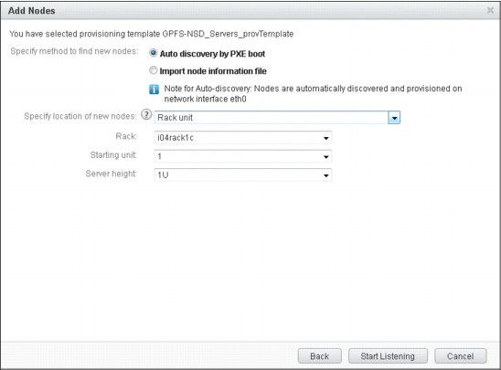
Figure 3-8 Provisioning template GPFS-NSD_Servers_provTemplate
|
Note: To use this provisioning method, you must define a discovery IP address range into the provisioning network at installation time. This discovery IP address range is used to assign a temporary IP address for collecting information about the host by using the auto node discovery method.
|
To define the cluster for our scenario, we used a host information file. As shown in Example 3-4, the first two compute nodes are used as GPFS server nodes (NSD servers) to share the disks to the cluster. We prefer to provision the GPFS nodes by using pHPC because all internal communication of GPFS relies on SSH, and it must exchange keys with all GPFS clients, which is automatically done by pHPC. Because the IP addresses of the NIC that is associated with the BMC of the nodes are configured, they are explicitly defined in the host-information-file. The nodes can have non-consecutive static IP addresses, as shown in Example 3-11 on page 89.
Example 3-4 Adding nodes by using host information file method
i04n51-gpfs1:
mac=E4:1F:13:84:40:F8
ip=129.40.64.51
nicips=bmc!129.40.65.51
i04n52-gpfs2:
mac=E4:1F:13:84:46:8C
ip=129.40.64.52
nicips=bmc!129.40.65.52
i04n53:
mac=E4:1F:13:4D:87:D8
ip=129.40.64.53
nicips=bmc!129.40.65.53
i04n54:
mac=E4:1F:13:4D:90:00
ip=129.40.64.54
nicips=bmc!129.40.65.54
i04n63:
mac=E4:1F:13:84:31:98
ip=129.40.64.63
nicips=bmc!129.40.65.63
i04n64:
mac=E4:1F:13:84:41:88
ip=129.40.64.64
nicips=bmc!129.40.65.64
You can start adding nodes to the cluster immediately after the pHPC installation by using the default provisioning template and default profiles, which is enough if you want to evaluate the product. In production, you must define your own provisioning template and all of its constituent components because you must add your other software, provision your custom networks, or modify hardware profiles according to your hardware.
We define all of the components of a provisioning template as is shown Figure 3-6 on page 80 from left to right and top to bottom.
The operating system (OS) distribution is a copy of the Linux distribution and service levels that are obtained from the operating system ISO files. OS distributions are packages that are used to distribute operating system software onto nodes. At creation time, each OS distribution is copied to a default destination directory under /install/OS-name/OS-arch, where OS-name is the distribution name and OS-arch is the OS architecture; for example: /install/rhels6.4/x86_64.
Platform HPC can create OS updates for an OS distribution that exists in the system. OS updates are stored in the /install/osdistroupdates directory and can be applied to compute nodes. For example, after the OS update is created, it is stored in the /install/osdistroupdates/OS-update-name directory. For provisioned compute nodes, the OS update can change the system configuration files or upgrade some software packages to a higher version.
Complete the following steps to add OS updates from a local directory:
1. Determine the name of the OS distribution you want to update, as shown in Example 3-5.
Example 3-5 Operating system distribution to be updated
[root@i04n50 ~]# lsdef -t osdistro
rhels6.4-x86_64 (osdistro)
[root@i04n50 ~]#
2. Copy the OS updates (Rational Portfolio Manager packages) to a directory (for example, /tmp/updates).
3. Create an OS update definition, as shown in Example 3-6.
Example 3-6 Creating an OS distribution update
[root@i04n50 ~]# pcmosdistroupdate -c rhels6.4-x86_64 -p /tmp/updates
Creating the OS distribution update for rhels6.4-x86_64 from /tmp/updates
Created OS distribution update rhels6.4-x86_64-2013-11-14_10-06.
[root@i04n50 ~]#
4. List the new OS update, as shown in Example 3-7.
Example 3-7 Listing the OS update
[root@i04n50 ~]# pcmosdistroupdate -l rhels6.4-x86_64
osdistroupdate name: rhels6.4-x86_64-2013-11-14_10-06
osdistroname=rhels6.4-x86_64
dirpath=/install/osdistroupdates/rhels6.4-x86_64-2013-11-14_10-06
downloadtime=2013-11-14_10-6
disable=0
[root@i04n50 ~]#
5. For the OS update to be accessible from the Web Portal, you must trigger the PERF loader. To trigger the PERF loader to update the database, run the command as shown in Example 3-8.
Example 3-8 Loaders start
[root@i04n50 ~]# plcclient.sh -d "pcmosdistroloader"
Loaders startup successfully.
[root@i04n50 ~]#
Cross Distribution cluster
Users often install homogeneous clusters where management nodes and compute nodes use the same OS Distribution. In some cases, the compute nodes can be different, so you can mix OS distributions in the same cluster. This is a Cross Distribution cluster.
To add a new OS Distribution, use the GUI (as shown in Figure 3-9 on page 86) and an ISO file. When a new OS Distribution is defined, two image profiles also are created: one stateful and one stateless. The image profiles are stored in the /install/osimages/* directory. For more information about an image profile, see “Image profiles” on page 100.
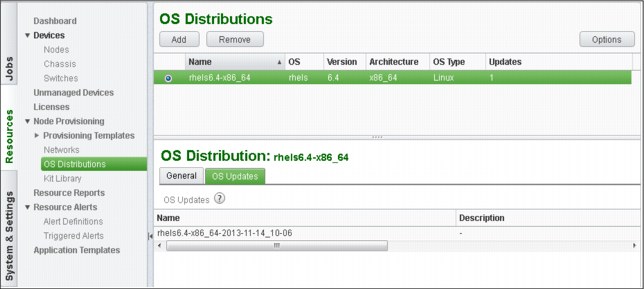
Figure 3-9 OS distributions window
Kit and kit components
In the IBM Platform HPC web interface, you see a menu that is named Kit Library, as shown in Figure 3-10.

Figure 3-10 IBM Platform HPC Kit Library menu
A Kit Library is a central repository in which you can store kits. These kits can be applied to different hardware architectures (for example, x86 or x64) or different OS distributions (for example, RHEL or SLES).
A kit is a pre-packed bundle that contains an application and its related components. A kit represents a mechanism to bundle an application with its installation scripts to make it easier to manage and deploy your cluster. Kits are used to deploy a single application on compute nodes. IBM Platform HPC ships with kits, such as Platform LSF, Platform MPI, and Platform PAC.
A kit component represents different parts of an application to be deployed into your cluster. You can have a client component and server component of an application bundled into the same kit. Platform LSF is a practical example; it is bundled into a kit that contains two kit components: Master component (installed on management nodes) and compute component (installed on compute nodes).
Kit components are used to install Platform products, but also can be used by users to install their own applications on the compute nodes. Within each kit component, a user can define which packages are installed and which scripts are run to configure the component.
If the kit is deployed on different hardware architectures (for example, x86 or x64) or different OS distributions (for example, RHEL or SLES), you must define a kit component that is installed only on that OS distribution for each architecture or each OS distribution.
A kit is an archive file (.tar) that contains the following components:
•Kit repositories: A directory for each operating system version in which this kit is supported. Each directory contains all of the product software packages that are required for that environment with repository metadata.
•Kit components: A metapackage that is built to ask for all product software dependencies and to automatically run installation and configuration scripts. It relies on the packages that are stored into kit repositories or OS distribution repositories.
•Kit component files: Scripts, deployment parameters, exclusion lists, and other files that are used to install and configure the kit components and product packages.
•Kit configuration file: A file that describes the contents of the kit that contains the following information:
– Kit name, version, description, supported OS distributions, license information, and deployment parameters.
– Kit repository information, including name, supported OS distributions, and supported architectures.
– Kit component information, including name, version, description, server roles, scripts, and other data.
•Documentation: Product documentation that is shipped as HTML files that can be displayed by using the GUI.
•Plug-ins: Used for other product configuration and customization during image management and node management.
To build a kit, you must use the tool that is shipped with pHPC that is called buildkit. This tool is used to generate a skeleton (template) for your new kit. It then compiles your modifications that were made into the skeleton and bundles all of your components into a kit. The following steps are used:
1. Building the skeleton of the kit is the process that is used to create a predefined subdirectories tree that are automatically populated with samples in which you can add your packages, scripts, parameters, and so on, as shown in Example 3-9 on page 88. In the next sections, we describe each subdirectory and file.
Example 3-9 Command syntax for buildkit
# buildkit create <kit_basename>
The command that is shown in Example 3-9 creates a subdirectory called kit_basename in your current directory, as shown in Figure 3-11.

Figure 3-11 Kit directory location
The subdirectory contains the following components:
•<kit directory location>: The full path name of the location that is specified on the command line or the current working directory in which you ran the buildkit command and the <kit_basename> that you provided.
•buildkit.conf: The sample kit build file.
•source_packages: This directory stores the source packages for kit packages and non-native packages. The buildkit CLI searches these directories for source packages when packages are built. This directory stores RPM spec and tarballs, source RPMs, pre-built RPMs, and non-native packages.
•scripts: Stores the kit deployment scripts.
•plug-ins: Stores the kit plug-ins. Samples are provided for each type of plug-in.
•docs: Stores the kit documentation files.
•other_files:
– kitdeployparams.lst: The kit deployment parameters file.
– exclude.lst: Contains files and directories to exclude from the stateless image.
•build: Stores files when the kit is built. For example, the kit .tar file kitname.tar.bz2. This directory is created only after you create the following repositories (buildkit buildrepo all):
– build/kit_repodir stores the fully built kit package repositories
– build/<kitbasename> stores the contents of the kit .tar file before it is archived in a .tar file
2. Modify the skeleton by adding your components. This is the phase in which you prepare your kit with all its components before it is bundled.
In our cluster scenario, we must install GPFS on two types of nodes: GPFS server nodes and GPFS client nodes. Our GPFS rpm files are of two types, as shown in Example 3-10.
Example 3-10 GPFS base release
[root@i04n50 gpfs.base]# ll
-rw-r--r-- 1 root root 12405953 Oct 25 21:05 gpfs.base-3.5.0-3.x86_64.rpm
-rw-r--r-- 1 root root 230114 Oct 25 21:05 gpfs.docs-3.5.0-3.noarch.rpm
-rw-r--r-- 1 root root 509477 Oct 25 21:05 gpfs.gpl-3.5.0-3.noarch.rpm
-rw-r--r-- 1 root root 99638 Oct 25 21:05 gpfs.msg.en_US-3.5.0-3.noarch.rpm
[root@i04n50 gpfs.base]#
As shown in Example 3-11, in the gpfs_updates directory, there is a file named gpfs.gplbin-*. This file is the GPFS portability layer.
Example 3-11 GPFS updates
[root@i04n50 gpfs.update]# ll
-rw-r--r-- 1 root root 13156422 Oct 25 21:13 gpfs.base-3.5.0-13.x86_64.update.rpm
-rw-r--r-- 1 root root 254205 Oct 25 21:13 gpfs.docs-3.5.0-13.noarch.rpm
-rw-r--r-- 1 root root 554372 Oct 25 21:13 gpfs.gpl-3.5.0-13.noarch.rpm
-rw-r--r-- 1 root root 1866576 Oct 25 21:13 gpfs.gplbin-2.6.32-358.el6.x86_64-3.5.0-13.x86_64.rpm
-rw-r--r-- 1 root root 106817 Oct 25 21:13 gpfs.msg.en_US-3.5.0-13.noarch.rpm
[root@i04n50 gpfs.update]#
GPFS portability layer and how to build it
On Linux platforms, GPFS uses a loadable kernel module that enables the GPFS daemon to interact with the Linux kernel. This kernel module is specific to each version of Linux and it must be built from the source code for each type of Linux. When GPFS is installed on Linux, you must build the portability layer (kernel module) that is based on your particular hardware platform and Linux distribution to enable communication between the Linux kernel and GPFS.
To make the deployment simpler to all compute nodes, after compiling the source code on a template node, you can build an rpm package (binary module) and reuse this rpm on all compute nodes that have the same hardware and Linux distribution.
Complete the following steps to build the portability layer:
1. Install all of the prerequisites, as shown in Example 3-12.
Example 3-12 Installing prerequisites
[root@i04n50]# yum install kernel-devel kernel-headers xorg-x11-xauth gcc-c++ imake libXp compat-libstdc++-33 compat-libstdc++-296 libstdc++
2. Compile the GPFS portability layer for the current environment, as shown in Example 3-13.
Example 3-13 Compiling to create the portability layer
[root@i04n50 /usr/lpp/mmfs/src]# make Autoconfig
[root@i04n50 /usr/lpp/mmfs/src]# make World
[root@i04n50 /usr/lpp/mmfs/src]# make InstallImages
|
Note: Building the portability layer assumes the GPFS main binaries are installed.
|
3. Build the RPM, as shown in Example 3-14.
Example 3-14 Building the rpm
[root@i04n50 /usr/lpp/mmfs/src]# make rpm
... (output truncated)
Wrote:
/root/rpmbuild/RPMS/x86_64/gpfs.gplbin-2.6.32-358.el6.x86_64-3.5.0-13.x86_64.rpm
... (output truncated)
[root@i04n50 /usr/lpp/mmfs/src]#
You cannot have in the same kit more than one component that refers to the same package name but different rpm name. For example, if you define two components into the same kit (one for base and one for updates) and make a dependency for updates to depend on the base, you might end up installing updates first and then base, which fails. In Example 3-15, you can see that the package name is different and the name inside is the same. This is correct because when you perform an update, the rpm tool knows exactly what to update.
Example 3-15 Running an update
[root@i04n50 gpfs.update]# rpm -qip gpfs.base-3.5.0-13.x86_64.update.rpm
Name : gpfs.base Relocations: (not relocatable)
Version : 3.5.0 Vendor: IBM Corp.
Release : 13 Build Date: Mon 30 Sep 2013 03:51:14 PM EDT
Install Date: (not installed) Build Host: bldlnxbc2b11.pok.stglabs.ibm.com
Group : System Environment/Base Source RPM: gpfs.base-3.5.0-13.src.rpm
Size : 38338955 License: (C) COPYRIGHT International
Signature : (none)
Packager : IBM Corp. <[email protected]>
URL : http://www.ibm.com/systems/software/gpfs/index.html
Summary : General Parallel File System
[root@i04n50 gpfs.update]#
[root@i04n50 gpfs.base]# rpm -qip gpfs.base-3.5.0-3.x86_64.rpm
Name : gpfs.base Relocations: (not relocatable)
Version : 3.5.0 Vendor: IBM Corp.
Release : 3 Build Date: Mon 20 Aug 2012 03:57:46 PM EDT
Install Date: (not installed) Build Host: bldlnxbc2b11.ppd.pok.ibm.com
Group : System Environment/Base Source RPM: gpfs.base-3.5.0-3.src.rpm
Size : 36313403 License: (C) COPYRIGHT International
Signature : (none)
Packager : IBM Corp. <[email protected]>
URL : http://www.ibm.com/servers/eserver/clusters/software/gpfs.html
Summary : General Parallel File System
[root@i04n50 gpfs.update]#
In building the GPFS kits for our cluster, we chose to build two kits. The first kit is the base kit and it is installed on all nodes (server and client nodes) in the same manner, and a second kit for updates. In the updates kit, we added two kit-components, one for updating the GPFS server nodes and the second for updating GPFS client nodes. The difference between them is that for the component of the GPFS client nodes (compute nodes), we added a post script that has the role of adding the node as a GPFS client.
In the next sections, you can find the details of both kits that we built. We start with the GPFS base kit and then continue with the GPFS updates kit. For the GPFS base kit, we added to the skeleton all the rpm files that we want to have into the kit (see /source_packages/gpfs.base, as shown in Example 3-16 on page 91).
Example 3-16 Source rpm files
[root@i04n50 gpfs.base]# ls –ltR
-rw-r--r-- 1 root root 1257 Oct 27 22:26 buildkit.conf
drwxr-xr-x 2 root root 4096 Oct 22 15:40 docs
drwxr-xr-x 3 root root 4096 Oct 22 15:40 other_files
drwxr-xr-x 8 root root 4096 Oct 29 14:38 plugins
drwxr-xr-x 3 root root 4096 Oct 22 15:40 scripts
drwxr-xr-x 4 root root 4096 Oct 25 21:18 source_packages
. . . (truncated)
./source_packages/gpfs.base:
-rw-r--r-- 1 root root 12405953 Oct 25 21:05 gpfs.base-3.5.0-3.x86_64.rpm
-rw-r--r-- 1 root root 230114 Oct 25 21:05 gpfs.docs-3.5.0-3.noarch.rpm
-rw-r--r-- 1 root root 509477 Oct 25 21:05 gpfs.gpl-3.5.0-3.noarch.rpm
-rw-r--r-- 1 root root 99638 Oct 25 21:05 gpfs.msg.en_US-3.5.0-3.noarch.rpm
[root@i04n50 gpfs.base]#
The skeleton includes a template configuration file that must be modified to reflect your needs. (In the documentation, you find in the buildkit.conf file.) For our GPFS base kit, Example 3-17 shows the kit configuration file that we used.
Example 3-17 buildkit.conf file
[root@i04n50 gpfs.base]# cat buildkit.conf
kit:
basename=gpfs
description=GPFS 3.5.0-3 base realease.
version=3.5.0
release=3
ostype=Linux
kitlicense=EPL
kitrepo:
kitrepoid=rhels6.4
osbasename=rhels
osmajorversion=6
osminorversion=4
osarch=x86_64
kitcomponent:
basename=component-gpfs-base
description=GPFS 3.5.0-3 base release
version=3.5.0
release=3
serverroles=mgtnode,compute
kitrepoid=rhels6.4
kitpkgdeps=gpfs.base,gpfs.docs,gpfs.msg.en_US,gpfs.gpl
kitpackage:
filename=gpfs.base-3.5.0-3.x86_64.rpm
kitrepoid=rhels6.4
isexternalpkg=no
rpm_prebuiltdir=gpfs.base
kitpackage:
filename=gpfs.docs-3.5.0-3.noarch.rpm
kitrepoid=rhels6.4
isexternalpkg=no
rpm_prebuiltdir=gpfs.base
kitpackage:
filename=gpfs.gpl-3.5.0-3.noarch.rpm
kitrepoid=rhels6.4
isexternalpkg=no
rpm_prebuiltdir=gpfs.base
kitpackage:
filename=gpfs.msg.en_US-3.5.0-3.noarch.rpm
kitrepoid=rhels6.4
isexternalpkg=no
rpm_prebuiltdir=gpfs.base
[root@i04n50 gpfs.base]#
For the GPFS updates, we built a kit that contains two kit components: one for the GPFS server nodes and one for the GPFS client nodes. The kit component for the client nodes is configured with another script that configures compute nodes as GPFS client nodes to access the network shared disks (NSD) servers, as shown in Example 3-18.
Example 3-18 Kit components for GPFS server and client nodes
[root@i04n50 gpfs.update]# cat buildkit.conf
kit:
basename=gpfs-update
description=GPFS 3.5.0-13 with portability layer
version=3.5.0
release=13
ostype=Linux
kitlicense=EPL
kitrepo:
kitrepoid=rhels6.4
osbasename=rhels
osmajorversion=6
osminorversion=4
osarch=x86_64
kitcomponent:
basename=component-gpfs-updates
description=GPFS 3.5.0-13 updates, and portab. layer built into kernel
version=3.5.0
release=13
serverroles=mgtnode,compute
kitrepoid=rhels6.4
kitcompdeps=component-gpfs-base
kitpkgdeps=gpfs.base,gpfs.docs,gpfs.msg.en_US,gpfs.gpl,gpfs.gplbin
kitcomponent:
basename=component-gpfs-updates-compute
description=GPFS 3.5.0-13 updates, and portab. layer built into kernel
version=3.5.0
release=13
serverroles=mgtnode,compute
kitrepoid=rhels6.4
kitcompdeps=component-gpfs-base
kitpkgdeps=gpfs.base,gpfs.docs,gpfs.msg.en_US,gpfs.gpl,gpfs.gplbin
postinstall=gpfs-addnode.sh
kitpackage:
filename=gpfs.base-3.5.0-13.x86_64.update.rpm
kitrepoid=rhels6.4
isexternalpkg=no
rpm_prebuiltdir=gpfs.update
kitpackage:
filename=gpfs.docs-3.5.0-13.noarch.rpm
kitrepoid=rhels6.4
isexternalpkg=no
rpm_prebuiltdir=gpfs.update
kitpackage:
filename=gpfs.msg.en_US-3.5.0-13.noarch.rpm
kitrepoid=rhels6.4
isexternalpkg=no
rpm_prebuiltdir=gpfs.update
kitpackage:
filename=gpfs.gpl-3.5.0-13.noarch.rpm
kitrepoid=rhels6.4
isexternalpkg=no
rpm_prebuiltdir=gpfs.update
kitpackage:
filename=gpfs.gplbin-2.6.32-358.el6.x86_64-3.5.0-13.x86_64.rpm
kitrepoid=rhels6.4
isexternalpkg=no
rpm_prebuiltdir=gpfs.update
[root@i04n50 gpfs.update]#
By studying the configuration file that is shown in Example 3-18 on page 92, you can see that the two kit components have dependencies on the GPFS base components. This means that you cannot install the update components if the base component is not installed.
The kit skeleton for the GPFS updates is shown in Example 3-19.
Example 3-19 Kit skeleton for the GPFS updates
[root@i04n50 gpfs.update]# ls -ltR
-rw-r--r-- 1 root root 1889 Oct 29 16:50 buildkit.conf
drwxr-xr-x 2 root root 4096 Oct 22 15:40 docs
drwxr-xr-x 3 root root 4096 Oct 22 15:40 other_files
drwxr-xr-x 2 root root 4096 Oct 22 15:40 plugins
drwxr-xr-x 3 root root 4096 Oct 30 09:41 scripts
drwxr-xr-x 4 root root 4096 Oct 25 21:29 source_packages
. . . (truncated )
./scripts:
-rwxr-xr-x 1 root root 1749 Oct 30 09:41 gpfs-addnode.sh
drwxr-xr-x 2 root root 4096 Oct 22 15:40 sample
. . . (truncated )
./source_packages:
drwxr-xr-x 2 root root 4096 Oct 25 21:29 gpfs.update
drwxr-xr-x 6 root root 4096 Oct 22 15:40 sample
./source_packages/gpfs.update:
-rw-r--r-- 1 root root 1866576 Oct 25 21:13 gpfs.gplbin-2.6.32-358.el6.x86_64-3.5.0-13.x86_64.rpm
-rw-r--r-- 1 root root 106817 Oct 25 21:13 gpfs.msg.en_US-3.5.0-13.noarch.rpm
-rw-r--r-- 1 root root 554372 Oct 25 21:13 gpfs.gpl-3.5.0-13.noarch.rpm
-rw-r--r-- 1 root root 13156422 Oct 25 21:13 gpfs.base-3.5.0-13.x86_64.update.rpm
-rw-r--r-- 1 root root 254205 Oct 25 21:13 gpfs.docs-3.5.0-13.noarch.rpm
. . . (truncated )
[root@i04n50 gpfs.update]#
The kit component that is installed on compute nodes includes a script (gpfs-addnode.sh) that adds the compute nodes as GPFS clients. Take care when you are copying and pasting “” (see Example 3-20), because we assume that the GPFS server nodes are installed and configured. For this reason, we first install and configure the GPFS server nodes, and then the client nodes while we are building our cluster.
Example 3-20 gpfs-addnode script
[root@i04n50 scripts]# cat gpfs-addnode.sh
#!/bin/bash
# Define the primary and secondary GPFS configuration servers
PRIMARY=i04n51-gpfs1
SECONDARY=i04n52-gpfs2
CONFIGnode=$PRIMARY
# Collect current GPFS configuration from the GPFS configuration nodes
######################################################################################
CLUSTER=$(ssh -o "StrictHostKeyChecking=no" ${PRIMARY} /usr/lpp/mmfs/bin/mmlscluster)
if [ "$CLUSTER" == "" ];
then
CLUSTER=$(ssh -o "StrictHostKeyChecking=no" ${SECONDARY} /usr/lpp/mmfs/bin/mmlscluster)
CONFIGnode=$SECONDARY
if [ "$CLUSTER" == "" ];
then
exit 111
fi
fi
# Determine if current node is a member of the GPFS cluster
######################################################################################
MYIPS=$(ip addr | grep "inet " |awk '{print $2}' | cut -f 1 -d / | grep -v 127.0.0.1)
for IP in $MYIPS
do
GPFSHOSTNAME=$(echo "$CLUSTER"| grep $IP | awk '{print $2}')
if [ "$GPFSHOSTNAME" ];
then
break
fi
done
# Add or restore node configuration
######################################################################################
if [ "$GPFSHOSTNAME" == "" ];
then
# This node is not part of GPFS cluster; let's add it
ssh -o "StrictHostKeyChecking=no" ${CONFIGnode} /usr/lpp/mmfs/bin/mmaddnode -N `hostname`
sleep 5
/usr/lpp/mmfs/bin/mmchlicense client --accept -N `hostname`
sleep 5
/usr/lpp/mmfs/bin/mmstartup
sleep 5
/usr/lpp/mmfs/bin/mmmount all
echo 'PATH=$PATH:/usr/lpp/mmfs/bin' >> /etc/profile
else
# This node is defined in GPFS cluster; let's restore the GPFS database into this node
/usr/lpp/mmfs/bin/mmsdrrestore -p ${CONFIGnode} -R /usr/bin/scp
sleep 5
/usr/lpp/mmfs/bin/mmstartup
sleep 5
/usr/lpp/mmfs/bin/mmmount all
echo 'PATH=$PATH:/usr/lpp/mmfs/bin' >> /etc/profile
fi
[root@i04n50 scripts]#
4. Bundle the kit and add it to pHPC.
After you add all of your packages, scripts, and application parameters to the skeleton, you must validate your configuration by building the kit package repositories, followed by building the archive.
Validating the configuration of the kit is the process of parsing all of the information that you added to the skeleton and checking it to ensure that every statement in the buildkit.conf file is valid (for example, the scripts exists into the skeleton and can be run), as shown in Example 3-21.
Example 3-21 Validates the configuration
root@i04n50 gpfs.base]# buildkit chkconfig
No errors were found in Kit Build File /gpfs.base/buildkit.conf.
[root@i04n50 gpfs.base]#
After the validation is completed successfully, we can build our kit, as shown in Example 3-22.
Example 3-22 Building the kit
[root@i04n50 gpfs.base]# buildkit buildrepo all
Spawning worker 0 with 4 pkgs
Workers Finished
Gathering worker results
Saving Primary metadata
Saving file lists metadata
Saving other metadata
Generating sqlite DBs
Sqlite DBs complete
[root@i04n50 gpfs.base]#
This process includes the following overall steps:
1. Create a directory that acts as a repository into the named Kit Package Repository: < Kit directory location >/build/kit_repodir/<Kit-Pkg-Repo>.
2. Build the Component Metapackages that are associated with the Kit Package Repository and add all related packages to the Kit Package Repository directory.
3. Build the repository metadata for the Kit Package Repository. The repository metadata is based on the OS native package format. For example, for RHEL, we build the YUM repository metadata by using the createrepo command.
After the repository is built, the skeleton receives several other directories that are generated by the build command (see Example 3-23).
Example 3-23 Directories that are generated by the build command
[root@i04n50 gpfs.base]# ls -ltR
drwxr-xr-x 4 root root 4096 Oct 29 14:38 build
drwxr-xr-x 8 root root 4096 Oct 29 14:38 rpmbuild
drwxr-xr-x 2 root root 4096 Oct 29 14:38 tmp
-rw-r--r-- 1 root root 1257 Oct 27 22:26 buildkit.conf
drwxr-xr-x 4 root root 4096 Oct 25 21:18 source_packages
drwxr-xr-x 3 root root 4096 Oct 22 15:40 scripts
drwxr-xr-x 2 root root 4096 Oct 22 15:40 docs
drwxr-xr-x 3 root root 4096 Oct 22 15:40 other_files
./build:
drwxr-xr-x 3 root root 4096 Oct 29 14:38 gpfs-3.5.0-3
drwxr-xr-x 3 root root 4096 Oct 29 14:38 kit_repodir
./build/gpfs-3.5.0-3:
lrwxrwxrwx 1 root root 43 Oct 29 14:38 repos -> /gpfs.base/build/kit_repodir
-rw-r--r-- 1 root root 934 Oct 29 14:38 kit.conf
./build/kit_repodir:
drwxr-xr-x 3 root root 4096 Oct 29 14:38 gpfs-3.5.0-3-rhels-6.4-x86_64
./build/kit_repodir/gpfs-3.5.0-3-rhels-6.4-x86_64:
drwxr-xr-x 2 root root 4096 Oct 29 14:38 repodata
-rw-r--r-- 1 root root 1459 Oct 29 14:38 component-gpfs-base-3.5.0-3.noarch.rpm
-rw-r--r-- 1 root root 12405953 Oct 25 21:05 gpfs.base-3.5.0-3.x86_64.rpm
-rw-r--r-- 1 root root 230114 Oct 25 21:05 gpfs.docs-3.5.0-3.noarch.rpm
-rw-r--r-- 1 root root 509477 Oct 25 21:05 gpfs.gpl-3.5.0-3.noarch.rpm
-rw-r--r-- 1 root root 99638 Oct 25 21:05 gpfs.msg.en_US-3.5.0-3.noar.rpm
./build/kit_repodir/gpfs-3.5.0-3-rhels-6.4-x86_64/repodata:
-rw-r--r-- 1 root root 2979 Oct 29 14:38 repomd.xml
-rw-r--r-- 1 root root 9690 Oct 29 14:38 7149( ... truncated )528-primary.sqlite.bz2
-rw-r--r-- 1 root root 5096 Oct 29 14:38 5d94( ... truncated )354-filelists.sqlite.bz2
-rw-r--r-- 1 root root 932 Oct 29 14:38 d87c( ... truncated )cdc-other.sqlite.bz2
-rw-r--r-- 1 root root 2995 Oct 29 14:38 228b( ... truncated )896-primary.xml.gz
-rw-r--r-- 1 root root 451 Oct 29 14:38 3b7e( ... truncated )f9c-other.xml.gz
-rw-r--r-- 1 root root 3970 Oct 29 14:38 eb19( ... truncated )203-filelists.xml.gz
[root@i04n50 gpfs.base]#
4. After successfully building your repositories into the skeleton, pack all files into a .tar file, which is added later to the pHPC as a kit, as shown in Example 3-24.
Example 3-24 Building the .tar file
[root@i04n50 gpfs.base]# buildkit buildtar
Kit tar file /gpfs.base1/gpfs-3.5.0-3.tar.bz2 successfully built.
[root@i04n50 gpfs.base]#
|
Note: If you must build repositories for OS distributions, versions, or architectures that do not match the current system, you might need to copy your kit template directory to an appropriate server to build that repository, and then copy the results back to your main build server.
|
Now that our kit is built, we can add it to the pHPC database by using the GUI, as shown in Figure 3-12.
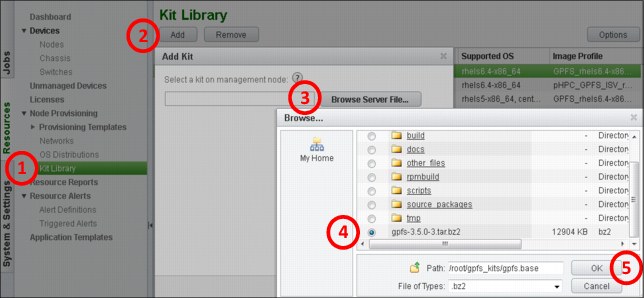
Figure 3-12 Kit Library GUI
Network profiles
A network profile defines the network interface configurations that are used by a compute node that is deployed through pHPC. to build a network profile to be applied to a compute node during the provisioning phase, we must define the building blocks of a network profile. The building blocks are the logical networks and interfaces.
You can define many types of logical networks according to your needs. A network is represented by a subnet and includes an IP address range and a gateway.
Normally, you define a logical network that is based on your cluster requirements. For example, in our cluster during the installation, we defined two logical networks for two purposes: one on which we provision the compute nodes, and the second is a BMC network that is used for remote hardware management. But as this cluster is not built only for compute nodes provisioning, we must build a network for the application’s communication that is installed on the nodes. All of the communication between the nodes of the application flows through this network, as shown in Figure 3-13 on page 98.
|
Note: At this point, we do not describe any association of this network with any of the interfaces of the compute nodes. A logical network definition is a subnet, which includes an IP address range and a gateway.
|

Figure 3-13 Network configuration profile
During the installation phase of pHPC, a default network profile is created, which includes the provisioning and BMC networks that were defined during the installation process, as shown in Figure 3-14.
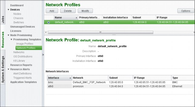
Figure 3-14 Network Profile GUI
This network profile is enough to provision your compute nodes. However, if you need more networks to define a new network profile (see Figure 3-14 on page 98), add the logical networks that you defined (for example, ISV-Application-Network) and the predefined logical networks (provision and Default_BMC_FSP_Network).
To add a network profile for provisioning the compute nodes and another network for the application, complete the steps that are shown in Figure 3-13 on page 98.
In some environments (which is not the case for our cluster), it might be necessary to build a bonding interface out of few available interfaces on the compute nodes. To do this, you must create a script that performs the bonding and place it into the /install/postscripts directory.
The best option while creating this script is to build a generic script, which accepts the bonding-config.sh bond0 eth1 eht2 parameters. Figure 3-15 shows how to associate a logical network to a bonding interface.
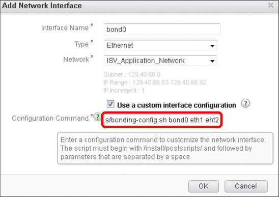
Figure 3-15 Adding a network interface GUI
Image profiles
Image profiles represent a logical definition of what is provisioned on the compute nodes, including the operating system image and other software (kits) with its configuration scripts, postinstallation and post-boot scripts, and eventual custom packages and kernel modules, as shown in Figure 3-16.

Figure 3-16 Image profiles
Image profiles are used to provision and eventually update the compute nodes with all the software linked (added) to the image profile.
|
Note: While you are working (adding or modifying) with an image profile, if you add a package that has dependencies, the related dependent packages are automatically installed.
|
Remember that an image profile is associated (linked) to a compute node, and any modification you make to an image profile makes the node out of sync. After you finish your modifications to your existing profile, you can synchronize all of the nodes that use that image profile.
If you do not know exactly which nodes are potentially affected by this image profile modification, click the menu Devices → Nodes (see Figure 3-17 on page 101), click Options and then click Image Profile. After this modification, you have a new colon in your Devices → Nodes window that is named Image Profile, which tells you the associated image profile for each node.
As shown in Figure 3-17, an image profile is always built on top of an OS distribution. Whenever you add an OS distribution to your pHPC database, two image profiles are automatically created, a stateful image profile and a stateless image profile. You cannot create an image profile from scratch, but you can create one by duplicating a pre-generated image (stateless of stateful) that was added by the OS distribution creation.
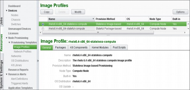
Figure 3-17 Image profiles GUI
Each OS distribution is copied to a default destination directory /install/OS-name/OS-arch, in which OS-name is the distribution name, and OS-arch is the OS architecture.
Stateful image profile is a package-based profile that helps to deploy the operating system and related software components onto persistent storage of compute nodes (local disk, SAN disk, or iSCSI device), and the changes that are made are persistent across node reboots.
Stateless image profile is an image-based profile that helps to deploy the operating system and related software components into memory, which makes the changes non-persistent across reboots. Installing a compute node by using a provisioning template that is based on a stateless image profile is faster because the compute node does not install all the packages at provisioning time. Instead, it uses a pre-generated stateless image (with all components) that is built and stored in the management node.
To create an image profile, you must make a copy of an existing image profile (that was built in by OS Distribution creation) and modify it according to your needs, as shown in Figure 3-18.

Figure 3-18 Image Profiles creation
|
Note: An image profile can be deleted only if it is not used by any nodes and provisioning templates. You cannot delete image profiles that were created by the installer.
|
In our cluster scenario, we intend to install the GPFS NSD servers by using pHPC because it has an advantage in that the SSH key exchange between the nodes is automatically done by pHPC.
For this reason, we are modifying the image profile we created and customizing it according to our needs, as shown in Figure 3-19. To modify your new image profile, select your image profile in the list and click Modify. A window opens that includes many tabs for changing different aspects of your image profile.
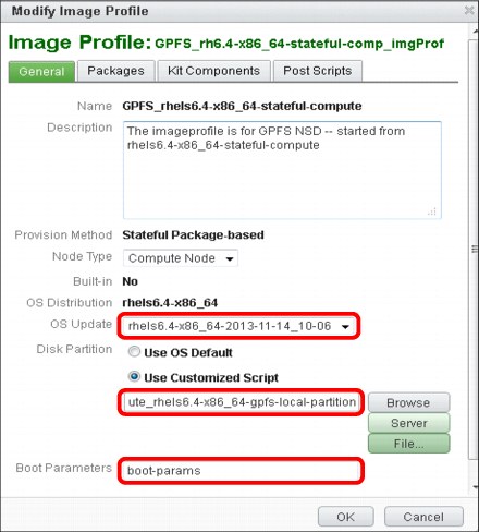
Figure 3-19 Modifying the image profile GUI
In the first tab, you can modify several key parameters of your profile. The first option is to choose whether you want to update the OS distribution on which this image profile was built when you perform the node provisioning. By default, it does not update the OS distribution.
If you want to instruct the installer on how to partition your local disks on the compute nodes, add a file into the /install/partitionscripts directory that contains your partitioning layout. For example, in our scenario, we need a certain layout of the internal disks of the GPFS NSD servers as we share only internal disks of these nodes to our compute nodes. Although this is not a recommended setup for a production environment, it is sufficient for our demonstration purposes.
Example 3-25 on page 104 shows the partitioning layout that we used for our setup.
Example 3-25 Partition layout
[root@i04n50 partitionscripts]# cat GPFS_compute_rhels6.4-x86_64-gpfs-local-partition
#!/bin/sh
# Use Anaconda to create and format LVM partition
cat << EOF > /tmp/partitionfile
bootloader --location=partition --driveorder=sda
clearpart --all --drives=sda --initlabel
#For UEFI machine, /boot/efi is necessary for using
part /boot/efi --size=100 --fstype vfat --ondisk=sda
part /boot --fstype ext4 --size=200 --ondisk=sda
part /gpfs --fstype ext4 --size=100000 --ondisk=sda
part pv.00 --size=100 --grow --asprimary --ondisk=sda
volgroup rootvg --pesize=32768 pv.00
logvol / --fstype ext4 --name=rootlv --vgname=rootvg --size=8192
logvol swap --fstype swap --name=swaplv --vgname=rootvg --size=1024 --grow --maxsize=4096
EOF
[root@i04n50 partitionscripts]#
|
Note: For our scenario, after the GPFS NSD nodes installation, we unmounted /gpfs, deleted its corresponding line from /etc/fstab, and then used the device /dev/sda4 as a GPFS NSD device.
|
As shown in Figure 3-20 on page 105, the Packages tab is where you can choose the packages that are installed during the provisioning phase. By default, not all of the packages from the OS distribution on which this image profile is built are installed. Therefore, if you still need some other packages that are not installed by default, you can select them from the OS Packages section, as shown in Figure 3-20 on page 105. The list of the packages is normally long and you can browse through the packages by using the arrows at the top of the list. If you are looking for specific packages and you know their names, you can use the Filter option.

Figure 3-20 Modifying image profile GUI
If you need to install custom packages (which are not present in the OS distribution), place these packages into the /install/contrib/OS-version/OS-architecture directory and then refresh the GUI by using the following command:
[root@i04n50]# plcclient.sh -d "pcmimageprofileloader“
|
Note: In our case scenario, we used a custom package as an example because it was not needed by any application or any other component.
|
As shown in Figure 3-21, by using the Kit Components tab, you can choose which KIT or Kit components are installed in your nodes. For example, for our GPFS NSD servers, we chose to install only gpfs-base, its corresponding updates (gpfs-updates), and phpc-base.

Figure 3-21 Modifying an image profile GUI
As shown in Figure 3-22 on page 107, by using the Post Scripts tab, you can specify which post scripts to run at boot or installation time. You can add the following types of custom scripts to an image profile:
•Post-install scripts are run on each node that is provisioned with this image profile only when the node is installed or reinstalled.
•Post-boot scripts are run on each node that is provisioned with this image profile each time the node is rebooted or during node update operations. If you modify the post-boot script, you must reboot the nodes or perform a synchronize operation.

Figure 3-22 Adding post scripts
For the stateless image profiles, you find the Kernel Modules tab in which you can specify other modules or drivers to be added to the kernel image initrd.img, as shown in Figure 3-23.
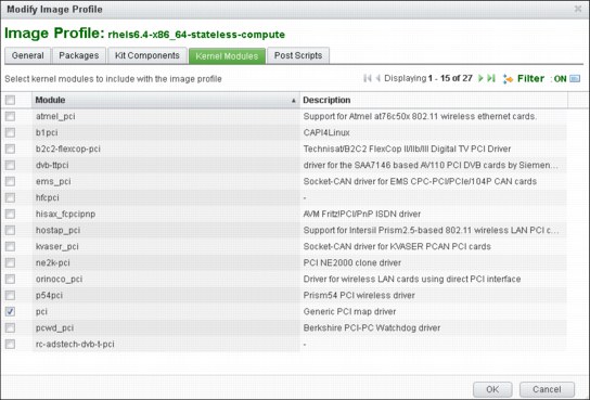
Figure 3-23 Kernel modules tab
The default initrd.img of stateless images contains a limited set of drivers and you might encounter errors when you provision stateless nodes because of the lack of drivers.
.
|
Note: Remember to use the Filter (green) option to filter for your specific needs. Also, the image profile can be deleted only if it is not used by any nodes and provisioning templates. You cannot delete image profiles that were created by the installer.
|
Hardware profiles
A hardware profile is a collection of parameters that are used by pHPC when remote management commands are run on different types of hardware. For example, to list your hardware profiles that are defined into your pHPC database, use the command as shown in Example 3-26.
Example 3-26 Listing hardware profiles from the Platform HPC database
[root@i04n50 ~]# tabdump nodehm
#node,power,mgt,cons,termserver,termport,conserver,serialport,serialspeed,serialflow,getmac,cmdmapping,comments,disable
"__HardwareProfile_IPMI",,"ipmi",,,,,"0","19200","hard",,"/opt/pcm/etc/hwmgt/mappings/HWCmdMapping_ipmi.xml",,
"__HardwareProfile_IBM_Flex_System_x",,"ipmi",,,,,"0","115200","hard",,"/opt/pcm/etc/hwmgt/mappings/HWCmdMapping_flex_x.xml",,
"__HardwareProfile_IBM_System_x_M4",,"ipmi",,,,,"0","115200","hard",,"/opt/pcm/etc/hwmgt/mappings/HWCmdMapping_rackmount_x.xml",,
"__HardwareProfile_IBM_iDataPlex_M4",,"ipmi",,,,,"0","115200","hard",,"/opt/pcm/etc/hwmgt/mappings/HWCmdMapping_rackmount_x.xml",,
"__HardwareProfile_IBM_idataplex_m3",,"ipmi",,,,,"0","115200","hard",,"/opt/pcm/etc/hwmgt/mappings/HWCmdMapping_idataplex_m3.xml",,
[root@i04n50 ~]#
|
Note: The last line in Example 3-26 is the definition of a profile that was added manually. We defined a new profile because we are using different hardware than the default that was predefined in pHPC.
|
To add a profile, use the command that is shown in Example 3-27.
Example 3-27 Adding a profile
[root@i04n50 ~]# pcmaddhwprofile name=IBM_idataplex_m3 type=ipmi cmdmapping=/opt/pcm/etc/hwmgt/mappings/HWCmdMapping_idataplex_m3.xml" serialspeed="115200" bmcportmode=dedicated bmcuser=USERID bmcpassword=PASSW0RD
where:
•cmdmapping is the xCAT mapping file that maps Platform Cluster Manager command to xCAT commands and is set to the absolute path of the mapping file.
•serialspeed is the serial speed number and is set to 115200, instead of the default value of 19200.
•bmcportmode is the BMC interface mode and is set to dedicated or shared for the hardware management profile type ipmi.
•bmcuser and bmcpassword is set to a valid BMC user name and password that is defined for the cluster.
|
Note: Because there were problems connecting to the serial console of the servers, we changed the default serial speed parameter 9600 - 115200. To make this change, you must run the tabedit nodehm command and modify the speed parameter; the tabedit command opens a vi editor.
|
Provisioning template
Now that we defined all of the components that are needed to build a provisioning template, we define the provisioning template. A provisioning template is a logical concept that exists only in the GUI that aggregates the software, network, and hardware attributes of a node. A provisioning template is built based on common characteristics (profiles) of nodes to be provisioned, including an image profile, network profile, and a hardware profile.
A provisioning template can be used to provision one node or several nodes at a time. The provisioning template is used only during provisioning phase.
The provisioning template is not attached to the nodes it was used to provision. When nodes are added to the cluster, they are linked (attached) to the image profile, network profile, and a hardware profile, not to the provisioning template.
The installer creates two templates (one stateful, one stateless), as shown in Figure 3-24.

Figure 3-24 Provisioning templates GUI
The two default provisioning templates are built based on the following default image, network, and hardware profiles:
•For stateful compute nodes it uses:
– Image profile = “<os-arch>-stateful-compute”
– Network profile = “default_network_profile”
– Hardware profile = IPMI
•For stateless compute nodes it uses:
– Image profile = “<os-arch>-stateless-compute”
– Network profile = “default_network_profile”
– Hardware profile = IPMI
Now that all of the components are described, we can create a provisioning template (see Figure 3-25) that is used for provisioning our GPFS NSD server nodes.
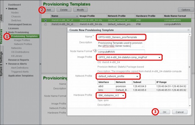
Figure 3-25 Creating provisioning templates
For our scenario to provision the GPFS NSD server nodes, you first must select the nodes into the GUI then click Reinstall, which starts a wizard that guides you through the provisioning process. Because of our preparation work in which the image, network, and hardware profiles were assigned to a provisioning template, we must use only this provisioning template to provision the node. You can see in Figure 3-25, after selecting the provisioning template, all of its components are displayed at the bottom of the wizard window.
Provisioning can garner the following results:
•Status: [Defined], [Installing], and [Booting Booted] where:
– Defined: The node that is added to cluster is deployed or reprovisioned when started.
– Installing (Stateful): Installing OS for stateful compute node (no such status if not power-on via GUI, thus, not available for first provisioning).
– Booting (Stateful only): In process to boot-up.
– Booted: The node is booted up successfully.
– Failed: Running the postbootscript failed.
Synchronization status indicates whether the node is in sync with the configuration of corresponding Image Profile. The available statuses are: “synced”, “out-of-sync”, or “-” (Unknown).
Limitation does not reflect the synchronization status for configuration files, which cannot be modified via GUI, for example, /etc/fstab and /etc/passwd.
The CFM function can be used from the GUI via the nodes’ Synchronize action or by using the updatenode command. Each Image profile has the following CFM-related files on the management node (MN), which determines what is synchronized:
/install/osimages/<Image_Profile>/synclist.cfm
/install/osimages/<Image_Profile>/pkglist.cfm
The synclist.cfm file contains a list of files to be synchronized from the management node to the client nodes by using the methods:
•Replacing the content of the destination file with the content of the source file. The source file is in the left of the arrow → (as shown in the following example) and represents a file on the management node. The destination is on the right side of the arrow → and represents the file to be modified on the destination compute node. For example, the following line is overwriting the content of /etc/hosts on the compute nodes with the content of /etc/hosts from the management node. This happens because …/cfmdir/etc/hosts file is a soft link to the following line:
/install/osimages/<Image_Profile>/cfmdir/etc/hosts → /etc/hosts
•Merging the content of source with destination file:
/install/osimages/<Image_Profile>/cfmdir/etc/passwd.merge → /etc/hosts
A complete example file for both methods is shown in Example 3-28.
Example 3-28 Replacing and merging files
/install/osimages/<Image_Profile>/cfmdir/etc/hosts -> /etc/hosts
MERGE:
/install/osimages/<Image_Profile>/cfmdir/etc/shadow.merge -> /etc/shadow
/install/osimages/<Image_Profile>/cfmdir/etc/group.merge -> /etc/group
/install/osimages/<Image_Profile>/cfmdir/etc/passwd.merge -> /etc/passwd
The cfmdir file acts as a repository that stores files to be pushed to compute nodes, as shown in Example 3-29. The files in the /install/osimages/<Image_Profile>/cfmdir/* directory can be flat files or soft links to the files on the management’s node file system (for example, hosts → /etc/hosts).
Example 3-29 cfmdir repository
[root@i04n50 cfmdir]# ls -l etc/*
lrwxrwxrwx 1 root root 16 Nov 12 11:56 group.merge -> /etc/group.merge
lrwxrwxrwx 1 root root 10 Nov 12 11:56 hosts -> /etc/hosts
lrwxrwxrwx 1 root root 17 Nov 12 11:56 passwd.merge -> /etc/passwd.merge
lrwxrwxrwx 1 root root 17 Nov 12 11:56 shadow.merge -> /etc/shadow.merge
[root@i04n50 etc]# cat /etc/group.merge
ngs2:x:31002:
phpcadmin:x:30495:
[root@i04n50 etc]#
The pkglist.cfm file contains a list of packages to be synchronized with the compute nodes. For example, if you define a package in this file and the package is part of the OS distribution that belongs to this Image Profile, the compute nodes are updated with this package when you run an updatenode command.
After GPFS NSD server nodes are provisioned by using the GPFS-NSD_Servers_provTemplate, the nodes are ready to be configured as NSD nodes. During the provisioning, all GPFS software and updates are installed.
In the next section, we describe the steps that are used to configure the NSD nodes for our scenario. These nodes are used only for demonstration purposes. If you are deploying for production, plan according to your cluster needs. Each NSD node has one internal disk, which we use as a shared disk by replicating the data across nodes. Remember that our Image Profile included a partitioning script that creates an ext4 partition that is mounted under the /gpfs directory. We reuse this partition and allocate it to GPFS to be used as an NSD disk.
|
Note: Unmount the /gpfs directory and comment its corresponding line in /etc/fstab.
|
Complete the following steps to configure the NSD nodes:
1. Configure the profile of both nodes, as shown in Example 3-30.
Example 3-30 Profile configuration
[root@i04n50 ~]# echo 'PATH=$PATH:/usr/lpp/mmfs/bin' >> /etc/profile
[root@i04n50 ~]# . /etc/profile
2. Define the GPFS nodes as quorum nodes and file system managers by creating a file as shown in Example 3-31.
Example 3-31 Defining GPFS node and file system managers
[root@i04n50 ~]# cat /tmp/nodes
i04n51-gpfs1:manager-quorum
i04n52-gpfs2:manager-quorum
[root@i04n50 ~]#
3. Create the cluster as shown in Example 3-32.
Example 3-32 Creating the GPFS cluster
[root@i04n51-gpfs1 ~]# mmcrcluster -N /tmp/nodes -p i04n51-gpfs1 -s i04n52-gpfs2 -r /usr/bin/ssh -R /usr/bin/scp -C pHPC -U pbm.ihost.com –A
Warning: Permanently added 'i04n51-gpfs1' (RSA) to the list of known hosts.
Mon Oct 28 20:54:44 EDT 2013: mmcrcluster: Processing node i04n51-gpfs1
Mon Oct 28 20:54:44 EDT 2013: mmcrcluster: Processing node i04n52-gpfs2
mmcrcluster: Command successfully completed
mmcrcluster: Warning: Not all nodes have proper GPFS license designations.
Use the mmchlicense command to designate licenses as needed.
mmcrcluster: Propagating the cluster configuration data to all
affected nodes. This is an asynchronous process.
[root@i04n51-gpfs1 ~]#
4. List the configuration of your cluster and licensing, as shown in Example 3-33.
Example 3-33 Listing the cluster configuration
[root@i04n51-gpfs1 ~]# mmlscluster
===============================================================================
| Warning: |
| This cluster contains nodes that do not have a proper GPFS license |
| designation. This violates the terms of the GPFS licensing agreement. |
| Use the mmchlicense command and assign the appropriate GPFS licenses |
| to each of the nodes in the cluster. For more information about GPFS |
| license designation, see the Concepts, Planning, and Installation Guide. |
===============================================================================
GPFS cluster information
========================
GPFS cluster name: pHPC.i04n51-gpfs1
GPFS cluster id: 3691382246057379667
GPFS UID domain: pbm.ihost.com
Remote shell command: /usr/bin/ssh
Remote file copy command: /usr/bin/scp
GPFS cluster configuration servers:
-----------------------------------
Primary server: i04n51-gpfs1
Secondary server: i04n52-gpfs2
Node Daemon node name IP address Admin node name Designation
--------------------------------------------------------------------
1 i04n51-gpfs1 129.40.64.51 i04n51-gpfs1 quorum-manager
2 i04n52-gpfs2 129.40.64.52 i04n52-gpfs2 quorum-manager
5. Before you configure your cluster, you must accept the product license as shown in Example 3-34.
Example 3-34 Step to accept the license
[root@i04n51-gpfs1 ~]# mmchlicense server --accept -N i04n51-gpfs1,i04n52-gpfs2
The following nodes will be designated as possessing GPFS server licenses:
i04n51-gpfs1
i04n52-gpfs2
mmchlicense: Command successfully completed
mmchlicense: Propagating the cluster configuration data to all
affected nodes. This is an asynchronous process.
[root@i04n51-gpfs1 ~]
[root@i04n51-gpfs1 ~]# mmlslicense -L
Node name Required license Designated license
---------------------------------------------------------------------
i04n51-gpfs1 server server
i04n52-gpfs2 server server
Summary information
---------------------
Number of nodes defined in the cluster: 2
Number of nodes with server license designation: 2
Number of nodes with client license designation: 0
Number of nodes still requiring server license designation: 0
Number of nodes still requiring client license designation: 0
[root@i04n51-gpfs1 ~]#
6. Define the NSD shared disks, as shown in Example 3-35.
Example 3-35 Defining the NSD shared disks
[root@i04n50 ~]# cat /tmp/nsd
%nsd: device=/dev/sda3
servers=i04n51-gpfs1
usage=dataAndMetadata
failureGroup=11
%nsd: device=/dev/sda3
servers=i04n52-gpfs2
usage=dataAndMetadata
failureGroup=12
[root@i04n50 ~]#
7. Create the NSD, as shown in Example 3-36.
Example 3-36 Creating the NSD
[root@i04n51-gpfs1 ~]# mmcrnsd -F /tmp/nsd
mmcrnsd: Processing disk sda3
mmcrnsd: Processing disk sda3
mmcrnsd: Propagating the cluster configuration data to all
affected nodes. This is an asynchronous process.
[root@i04n51-gpfs1 ~]#
[root@i04n51-gpfs1 ~]# cat /tmp/nsd
# DiskName:ServerList::DiskUsage:FailureGroup:DesiredName:StoragePool
# /dev/sda3:i04n51-gpfs1::dataAndMetadata:11::
gpfs1nsd:::dataAndMetadata:11::system
# /dev/sda3:i04n52-gpfs2::dataAndMetadata:12::
gpfs2nsd:::dataAndMetadata:12::system
[root@i04n51-gpfs1 ~]#
[root@i04n51-gpfs1 ~]# mmlsnsd
File system Disk name NSD servers
---------------------------------------------------------------------------
(free disk) gpfs1nsd i04n51-gpfs1
(free disk) gpfs2nsd i04n52-gpfs2
[root@i04n51-gpfs1 ~]#
8. Before you can create a file system on the NSD disks that are defined in Example 3-36, the GPFS server cluster must be running on all nodes from which you are going to use an NSD disk, as shown in Example 3-37 on page 115.
Example 3-37 Starting up the GPFS cluster
[root@i04n51-gpfs1 ~]# mmstartup -a
Tue Oct 29 09:51:34 EDT 2013: mmstartup: Starting GPFS ...
[root@i04n51-gpfs1 ~]#
[root@i04n51-gpfs1 ~]# mmgetstate -a
Node number Node name GPFS state
------------------------------------------
1 i04n51-gpfs1 active
2 i04n52-gpfs2 active
[root@i04n51-gpfs1 ~]#
9. Create the file system that is shared across client nodes, as shown in Example 3-38.
Example 3-38 Creating the GPFS file system
[root@i04n51-gpfs1 ~]# mmcrfs /gpfs1 /dev/gpfs1 -F /tmp/nsd -B 256k -n 100 -v no -R 2 -M 2 -r 2 -m2
The following disks of gpfs1 will be formatted on node i04n51-gpfs1:
gpfs1nsd: size 102400000 KB
gpfs2nsd: size 102400000 KB
Formatting file system ...
Disks up to size 912 GB can be added to storage pool system.
Creating Inode File
Creating Allocation Maps
Creating Log Files
80 % complete on Tue Oct 29 09:53:25 2013
100 % complete on Tue Oct 29 09:53:26 2013
Clearing Inode Allocation Map
Clearing Block Allocation Map
Formatting Allocation Map for storage pool system
52 % complete on Tue Oct 29 09:53:31 2013
100 % complete on Tue Oct 29 09:53:36 2013
Completed creation of file system /dev/gpfs1.
mmcrfs: Propagating the cluster configuration data to all
affected nodes. This is an asynchronous process.
[root@i04n51-gpfs1 ~]#
[root@i04n51-gpfs1 ~]# mmlsfs all
File system attributes for /dev/gpfs1:
======================================
flag value description
------------------- ------------------------ -----------------------------------
-f 8192 Minimum fragment size in bytes
-i 512 Inode size in bytes
-I 16384 Indirect block size in bytes
-m 2 Default number of metadata replicas
-M 2 Maximum number of metadata replicas
-r 2 Default number of data replicas
-R 2 Maximum number of data replicas
-j cluster Block allocation type
-D nfs4 File locking semantics in effect
-k all ACL semantics in effect
-n 100 Estimated number of nodes that will mount file system
-B 262144 Block size
-Q none Quotas enforced
none Default quotas enabled
--filesetdf No Fileset df enabled?
-V 13.23 (3.5.0.7) File system version
--create-time Tue Oct 29 09:53:22 2013 File system creation time
-u Yes Support for large LUNs?
-z No Is DMAPI enabled?
-L 4194304 Logfile size
-E Yes Exact mtime mount option
-S No Suppress atime mount option
-K whenpossible Strict replica allocation option
--fastea Yes Fast external attributes enabled?
--inode-limit 200704 Maximum number of inodes
-P system Disk storage pools in file system
-d gpfs1nsd;gpfs2nsd Disks in file system
--perfileset-quota no Per-fileset quota enforcement
-A yes Automatic mount option
-o none Additional mount options
-T /gpfs1 Default mount point
--mount-priority 0 Mount priority
[root@i04n51-gpfs1 ~]#
|
Note: From a performance perspective, it is recommended that you set the GPFS block size to match the application buffer size, the RAID stripe size, or a multiple of the RAID stripe size. If the GPFS block size does not match the RAID stripe size, performance can be severely degraded, especially for write operations. For more information about the mmcrfs command, see IBM GPFS 3.5: Advanced Administration Guide, SC23-5182-05.
|
10. Mount the file system on all NSD server nodes, as shown in Example 3-39.
Example 3-39 Mounting the file system
[root@i04n51-gpfs1 ~]# mmmount gpfs1 -a
Tue Oct 29 09:57:31 EDT 2013: mmmount: Mounting file systems ...
[root@i04n51-gpfs1 ~]#
[root@i04n51-gpfs1 ~]# df -h
Filesystem SizeUsedAvailUse%Mounted on
/dev/mapper/rootvg-rootlv7.9G1.1G6.5G15%/
Tmpfs 12G012G0%/dev/shm
/dev/sda2 97M32M61M35%/boot
/dev/sda1 100M252K100M1%/boot/efi
/dev/gpfs1 196G1.1G195G1%/gpfs1
[root@i04n51-gpfs1 ~]#
[root@i04n51-gpfs1 ~]# mmlsmount all -L
File system gpfs1 is mounted on 2 nodes:
129.40.64.51 i04n51-gpfs1
129.40.64.52 i04n52-gpfs2
[root@i04n51-gpfs1 ~]#
The GPFS NSD server nodes now are fully configured and they can be used to add more client nodes to the GPFS cluster by using an automate process during compute nodes provisioning.
3.2.8 IBM Platform HPC high availability
In our cluster scenario, we plan for high availability of the management nodes and Platform LSF installation on the management nodes. The high availability can be achieved by adding a secondary management node, which can take over the services if the primary (initial) management node fails. In this case, we can say that the high availability mode is active-standby where the active management node provides the corresponding services and the standby management node takes over all the services when active node is down.
The primary management node is the active node after the initial high availability enablement. The configuration data of this node before high availability enablement becomes the configuration data of the high availability cluster. It also acts as the primary master node for workload management.
Secondary management node is the standby node after the initial high availability enablement and acts as a failover node that takes over the services and become active when the primary management node goes down (fails).
Shared resources
Because the standby node takes over if the active nodes goes down, it must access all of the configuration data of the downed node (OS distributions, kit components, profiles, provisioning templates, and so on). The standby node also must take over the IP address of the active node to provide the corresponding services to the compute nodes or the users.
The shared storage server is an external storage server that stores all of the configuration data of management nodes, the user HOME directories, and system working directories. Normally, this shared storage is an NFS server that can provide access for the management nodes and users to their resources.
Virtual IP is a floating IP that is always configured on the active management node to provide services to the users (for example, access to active Platform LSF queue) and compute nodes (for example, NTP and syslog).
High availability
High Availability of the management nodes is accomplished by using EGO service, which is also known as high availability (HA) manager. HA manager runs on the management nodes and monitors the health of local services. If some of the services become unavailable, they are restarted. HA manager monitors these services via HA service agents.
At the same time, the HA manager also is monitoring the management node peers through a heartbeat signal. If the active node is down or if the HA manager detects unrecoverable errors, it migrates all controlled services to the standby (failover) node.
When a high availability solution is built, the following constraints apply to the management nodes:
•The management nodes must have the same or similar hardware.
•The management nodes must have the same partitioning layout, the same network settings, and must use the same network interfaces to connect to the provision and public networks.
•The management nodes must be configured with the same time, time zone, and current date.
•The virtual IP address is in the IP range of the corresponding networks on the primary management node.
IBM Platform HPC supports the following methods for setting up a high available environment:
•High availability environment fresh set up
•High availability environment setup on an existing cluster
The high availability environment fresh setup is simple and can be performed by following the installation manual of IBM Platform HPC. In our example scenario, we did not configure the high availability from the scratch; therefore, we configure it at this stage. The procedure for building the high availability on an existing environment has some similarities with a fresh setup, but many things are different because the existing cluster must be reconfigured.
As always in an existing cluster, there are compute nodes running that depend on the cluster services that are running on the management node (for example, NFS server and NTP, syslog). The compute nodes are configured to ask for these services to the provisioning IP address of the management node. However, because this IP address is replaced by the virtual IP address, all of the compute nodes must be reconfigured or reprovisioned. Also, the IP address of the shared storage server is changed and the compute nodes must become aware.
The recommended method to use is to reprovision all the compute nodes.
|
Note: Setting up the Platform HPC environment temporarily affects the operation of the cluster. It must be scheduled to avoid affecting users of the environment.
|
To set up the high availability environment for an existing IBM Platform HPC cluster, you should use the steps that are described next.
Installing Platform HPC on the failover node
Before you set up the high availability environment, you must install IBM Platform HPC on the failover management node with the same version of IBM Platform HPC ISO or DVD, and use the same installation options.
It is assumed the following tasks are complete:
•IBM Platform HPC is installed on the primary management node and the high availability environment is not set up.
•The operating system is installed in the secondary (failover) management node with the same partitioning layout as the primary and IBM Platform HPC is not yet installed.
To ensure that the secondary management node is installed with the same options as the primary management node, you must collect the following information about primary management node:
•Partitions layout
Run the df -h and fdisk -l commands on the primary and the secondary management nodes to check the partition layout and look for any inconsistency. If the failover node has a different partition layout, you should reinstall the operating system with the same partition layout.
The /install mount point on the secondary management node must be identical to the primary management node. Run the df -h /install command on the primary management node (as shown in Example 3-40 on page 119) to see which partition is used for the /install directory. Use the same partition mount point for the depot (/install) directory when the failover management node is installed.
Example 3-40 Checking partition information about the management nodes
[root@i04n50 ~]# df -h /install
Filesystem Size Used Avail Use% Mounted on
/dev/mapper/rootvg-lv_install
40G 6.0G 32G 16% /install
[root@i04n50 ~]#
[root@i04n49 ~]# df -h /install
Filesystem Size Used Avail Use% Mounted on
/dev/mapper/rootvg-lv_install
40G 176M 38G 1% /install
[root@i04n49 ~]#
|
Note: The /install directory was its own partition before enabling HA. Space is required on /install to install pHPC. After HA is enabled, /install is renamed to /install.PCMHA. pHPC had replicated files under /install that are needed from /install (which is now /install.pHPC) to the shared storage and created the link /install → /shared_phpc/install.
|
•Time and time zone
Reset the current date and time on the failover management node to ensure that the two management nodes have the same date and time, as shown in Example 3-41.
Example 3-41 Reset the day and time on the failover management node
[root@i04n49 ~]# date -s '20131125 10:31:00'
Collect the time zone that is defined on the primary management node and align both management nodes to the same time zone, as shown in Example 3-42.
Example 3-42 Collecting the time zone
[root@i04n50 ~]# lsdef -t site -o clustersite -i timezone
Object name: clustersite
timezone=America/New_York
[root@i04n50 ~]#
If the time zone is different on the secondary node, set up the time zone as shown in Example 3-43.
Example 3-43 Setting up similar time zones on the management nodes
[root@i04n50 ~]# echo 'ZONE="America/New_York"' > /etc/sysconfig/clock
[root@i04n50 ~]# ln –s /usr/share/zoneinfo/US/Eastern /etc/localtime
|
Note: On the SLES operating system, TIMEZONE is used instead of ZONE.
|
•Network settings
Complete the following steps to check and collect the network setting information:
a. Ensure that the failover and virtual IP addresses are not used by the compute nodes, as shown in Example 3-44.
Example 3-44 Checking for duplicate IP addresses
[root@i04n50 ~]# tabdump nics|grep 129.40.64.49
[root@i04n50 ~]# tabdump nics|grep 129.40.64.100
[root@i04n50 ~]# tabdump nics|grep 129.50.64.49
[root@i04n50 ~]# tabdump nics|grep 129.50.64.100
b. Ensure that the failover and virtual IP addresses are in the static IP address range, as shown in Example 3-45.
Example 3-45 Checking the IP addresses and their static IP address ranges
[root@i04n50 ~]# lsdef -t network -i staticrange,dynamicrange
Object name: Default_BMC_FSP_Network
dynamicrange=
staticrange=129.40.65.51-129.40.65.92
Object name: ISV_Application_Network
dynamicrange=
staticrange=129.40.66.51-129.40.66.92
Object name: provision
dynamicrange=129.40.64.230-129.40.64.254
staticrange=129.40.64.51-129.40.64.92
[root@i04n50 ~]#
In Example 3-46, the public virtual IP address is not in the IP range. This can be changed by changing the definition of the network object.
Example 3-46 Changing the network object definition
[root@i04n50 ~]# chdef -t network -o provision staticrange=129.40.64.49-129.40.64.100
[root@i04n50 ~]# chdef -t network -o public staticrange=129.50.64.49-129.50.64.100
|
Note: Ensure that the IP address range does not conflict with dynamic IP address range.
|
c. Ensure that the same network interfaces are used on the failover node to access the provision and public networks, as shown in Example 3-47 on page 121.
Example 3-47 Checking the network interfaces
[root@i04n50 ~]# lsdef i04n50 | grep nicips
nicips.eth0=129.40.64.50
nicips.eth1=129.50.64.50
[root@i04n50 ~]#
[root@i04n50 ~]# ping –c 2 –I eth0 129.40.64.49
[root@i04n50 ~]# ping –c 2 –I eth1 129.50.64.49
To get more installation options of the primary management node that is used as a reference when a secondary management node is installed, review the installation log file of IBM Platform HPC: /opt/pcm/log/phpc-installer.log.
After you collect all installation options on the primary management node and ensure that the failover node is consistent with the primary management node, run the IBM Platform HPC installer phpc-installer as user root. By using the installer, you can specify your installation options; however, ensure that you use the same installation options that were collected in the failover management node configuration.
For more information about installing IBM Platform HPC on the secondary management node, see 3.2.6, “Cluster deployment” on page 73.
Installing the high availability environment
If in your cluster you do not want to reprovision the compute nodes, complete the following steps before you set up high availability:
1. Shut down the entire Platform LSF cluster, as shown in Example 3-48.
Example 3-48 Shutting down Platform LSF
[root@i04n50 ~]# lsfshutdown –f
Shutting down all slave batch daemons ...
Shut down slave batch daemon on all the hosts? [y/n] y
Shut down slave batch daemon on <i04n50> ...... done
Shut down slave batch daemon on <i04n51-gpfs1> ...... Host control failed: Connection refused by server
Shut down slave batch daemon on <i04n52-gpfs2> ...... Host control failed: Connection refused by server
Shut down slave batch daemon on <i04n53> ...... done
Shut down slave batch daemon on <i04n54> ...... done
Shutting down all RESes ...
Do you really want to shut down RES on all hosts? [y/n] y
Shut down RES on <i04n51-gpfs1> ...... failed: A connect sys call failed: Connection refused
Shut down RES on <i04n52-gpfs2> ...... failed: A connect sys call failed: Connection refused
Shut down RES on <i04n50> ...... done
Shut down RES on <i04n53> ...... done
Shut down RES on <i04n54> ...... done
Shutting down all LIMs ...
Do you really want to shut down LIMs on all hosts? [y/n] y
Shut down LIM on <i04n50> ...... done
Shut down LIM on <i04n53> ...... done
Shut down LIM on <i04n54> ...... done
Trying unavailable hosts :
Shut down LIM on <i04n51-gpfs1> ...... ls_limcontrol: Communication time out
Shut down LIM on <i04n52-gpfs2> ...... ls_limcontrol: Communication time out
[root@i04n50 ~]#
Example 3-49 Removing /home and /share
[root@i04n50 ~]# updatenode __Managed 'mountnfs del'
i04n52-gpfs2: Wed Dec 18 14:56:36 EST 2013 Running postscript: mountnfs del
i04n54: Wed Dec 18 14:56:36 EST 2013 Running postscript: mountnfs del
i04n53: Wed Dec 18 14:56:36 EST 2013 Running postscript: mountnfs del
i04n51-gpfs1: Wed Dec 18 14:56:36 EST 2013 Running postscript: mountnfs del
i04n52-gpfs2: Postscript: mountnfs del exited with code 0
i04n52-gpfs2: Running of postscripts has completed.
i04n54: Postscript: mountnfs del exited with code 0
i04n54: Running of postscripts has completed.
i04n51-gpfs1: Postscript: mountnfs del exited with code 0
i04n51-gpfs1: Running of postscripts has completed.
i04n53: Postscript: mountnfs del exited with code 0
i04n53: Running of postscripts has completed.
. . .
[root@i04n50 ~]#
3. Add the shared storage server as an unmanaged node to the IBM Platform HPC cluster, as shown in Example 3-50.
Example 3-50 Adding the shared storage server
[root@i04n50 ~]# nodeaddunmged hostname=nfsserver ip=129.40.64.210
Created unmanaged node.
[root@i04n50 ~]#
This operation prevents the IP of the shared storage server (NFS server) from being allocated to a compute nodes. It also ensures that the NFS server name can be resolved consistently across the cluster.
4. Add the failover node entry to the /etc/hosts file on the primary management node, as shown in Example 3-51.
Example 3-51 Adding the failover node entry to /etc/hosts
[root@i04n50 ~]# echo “129.40.64.49 i04n49 i04n49.pbm.ihost.com i04n49-eth0” >> /etc/hosts
[root@i04n50 ~]# ping i04n49
5. Configure the password-less SSH connection between management nodes, as shown Example 3-52 on page 123.
Example 3-52 SSH configuration on the management nodes
[root@i04n50 ~]# cat /root/.ssh/id_rsa.pub > /root/.ssh/authorized_keys
[root@i04n50 ~]# ssh i04n49 “cp –rf /root/.ssh /root/.ssh.PCMHA”
root@i04n49's password:
[root@i04n50 ~]# scp –r /root/.ssh/* i04n49:/root/.ssh
root@i04n49's password:
authorized_keys 100% 393 0.4KB/s 00:00
config 100% 25 0.0KB/s 00:00
id_rsa 100% 1675 1.6KB/s 00:00
id_rsa.pub 100% 393 0.4KB/s 00:00
known_hosts 100% 2394 2.3KB/s 00:00
[root@i04n50 ~]# ssh i04n49 uptime
05:06:53 up 4 days, 1:03, 2 users, load average: 0.12, 0.11, 0.09
6. Verify that the shared storage server is available, as shown in Example 3-53.
Example 3-53 Verifying the availability of the shared storage server
[root@i04n50 ~]# showmount -e 129.40.64.210
Export list for 129.40.64.210:
/gpfs/fs21/cluster4/phpc4111/shared 129.40.66.0/24,129.40.64.0/24
/gpfs/fs21/cluster4/phpc4111/home 129.40.66.0/24,129.40.64.0/24
Configuring high availability
At this stage, the following assumptions are made:
•IBM Platform HPC was installed successfully on both management nodes and the high availability environment is not enabled.
•The password-less SSH connection is setup between the primary management node and the failover node.
•Shared file systems for high availability were created on the shared storage server and have sufficient free capacity.
The high availability environment can be enabled by using the HA management tool (pcmhatool). This tool defines the HA environment by using the predefined HA definition file.
Define a HA definition file according to your high availability environment configuration. The HA definition file example ha.info.example is in the /opt/pcm/share/examples/HA directory. For our scenario, we created the HA definitions file /root/ha.info, as shown in Example 3-54.
Example 3-54 HA definitions file
virtualmn:
nicips.eth1:0=129.50.64.100
nicips.eth0:0=129.40.64.100
sharefs_mntp.work=129.40.64.210:/gpfs/fs21/cluster4/phpc4111/shared
sharefs_mntp.home=129.40.64.210:/gpfs/fs21/cluster4/phpc4111/home
|
Note: You must use the IP address of the shared storage server that is connected to the provision network for the shared file systems.
|
Enable HA by using the following command:
# pcmhatool config -i ha-definition-file-path -s failover-node-name
|
Note: The HA management tool supports the Bash shell only.
|
After the enablement starts, the tool automatically parses your HA definition file and checks the hardware and software configurations. The tool displays the following information that is based on the results:
•OK: Indicates that no problems are found for the checked item.
•WARNING: Indicates that the configuration of an item does not match the requirements; HA enablement continues despite the warnings.
•FAILED: The HA enablement quits if the tool cannot recover from an error.
|
Note: It takes approximately 30 - 90 minutes to set up high availability because of the synchronization process between the primary management node and the shared storage server.
|
Example 3-55 Setting up high availability
[root@i04n50 HA]# pcmhatool config -i ha.info -s i04n49
Setting up high availability between the management node 'i04n50' and the standby management node 'i04n49'. Do not perform any operations during this time.
Parsing high availability data... [ OK ]
================================================================
Virtual node name: virtualmn
Virtual IP address: eth0:0; 129.40.64.100
Shared work directory on: 129.40.64.210:/gpfs/fs21/cluster4/phpc4111/shared
Shared home directory on: 129.40.64.210:/gpfs/fs21/cluster4/phpc4111/home
================================================================
During the high availability setup, data is copied to shared directories
and IBM Platform HPC services are restarted several times.
Ensure that the external shared storage server and network connections are available.
Continue? (Y/N) [N]: Y
Checking if passwordless SSH is available... [ OK ]
Getting standby management node data... [ OK ]
Checking if the secondary management node is
consistent the management node... [ OK ]
Checking if the virtual network interface <eth0:0>
is available... [ OK ]
Checking if the virtual IP address <129.40.64.100>
is available... [ OK ]
Checking if the shared directory home is available... [ OK ]
Checking if the shared directory work is available... [ OK ]
Stopping services... [ OK ]
Synchronizing system work data. This can take
several minutes... [ OK ]
Synchronizing user home data. This can take
several minutes... [ OK ]
Starting the xCAT daemon... [ OK ]
Saving high availability data... [ OK ]
Starting high availability configuration on the management node...
Setting up hosts/resolv files: [ OK ]
Setting up dhcpd: [ OK ]
Setting up named: [ OK ]
Setting up shared file system for HA: [ OK ]
Setting up ntpd: [ OK ]
Setting up LSF configuration: [ OK ]
Setting up web portal: [ OK ]
Setting up Platform HPC configuration: [ OK ]
Updating management node: [ OK ]
Configured high availability on the management node.
Generating the high availability data file... [ OK ]
Starting high availability configuration on the standby management node...
High availability configured on the standby management node.
Starting IBM Platform HPC services... [ OK ]
Starting services on the failover node... [ OK ]
High availability setup is complete. The setup log file pcmhatool.log is located in the /opt/pcm/log directory.
To source the environment run the 'source /etc/profile.d/pcmenv.sh' command. This is not required for new login sessions.
It can take several minutes for all high availability services to start. To get the status of high availability services, run the 'pcmhatool check' command.
After IBM Platform HPC high availability is enabled, you can access the Web Portal at http://mgtnode-virtual-IP:8080, where mgtnode-virtual-IP
is the virtual management node IP address. If you are connected to a public network, you can also navigate to http://mgtnode-virtual-hostname:8080, where mgtnode-virtual-hostname is the virtual management node hostname.
If the HTTPS is enabled, you can access the Web Portal at https://mgtnode-virtual-IP:8443 or https://mgtnode-virtual-hostname:8443.
[root@i04n50 HA]#
|
Note: If the management node crashes during the HA environment set up process, you should run the command again to clean up the incomplete environment and then restart the HA setup environment.
You can find the log file pcmhatool.log in /opt/pcm/log directory. This log file includes details and results about the HA environment setting up.
|
Verifying the high availability environment
The high availability status can be seen on the Web Portal or the CLI.
Showing HA status on WEN portal
Log in to the Platform HPC Web Portal with the management node virtual IP address. After you log in, the Resource Dashboard is displayed in the Web Portal. You can see two management node statuses in the Cluster Health panel. The current role (management node or failover node) also is shown behind the node name, as shown in Figure 3-26.
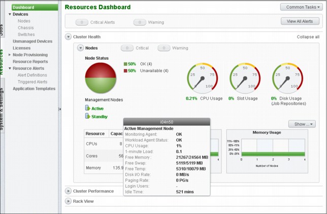
Figure 3-26 WEN Portal Resource Dashboard
The management node is the current active node where all services are running. The failover node is the node that is running in standby mode.
Showing HA status on the CLI
Displaying the HA status displays the current high availability status, including the state of the nodes, failover mode, and the status of running services, as shown in Example 3-56.
Example 3-56 Showing high availability status
[root@i04n50 ~]# pcmhatool status
Primary management node name: i04n50 [ok]
Secondary management node name: i04n49 [ok]
Failover mode: Automatic
Cluster management services running on: i04n50
Workload management services running on: i04n50
[root@i04n50 ~]#
To display the HA status for the HA manager and service agents, run the service phpc status command. All services must be in the STARTED state, as shown in Example 3-57 on page 127.
Example 3-57 Displaying the HA manager and service agent statuses
[root@i04n50 ~]# service phpc status
Show status of the LSF subsystem
lim (pid 3410) is running...
res (pid 3412) is running...
sbatchd (pid 3415) is running... [ OK ]
SERVICE STATE ALLOC CONSUMER RGROUP RESOURCE SLOTS SEQ_NO INST_STATE ACTI
JOBDT STARTED 9 /Manage* Manag* i04n50 1 1 RUN 115
PLC2 STARTED 6 /Manage* Manag* i04n50 1 1 RUN 116
WEBGUI STARTED 4 /Manage* Manag* i04n50 1 1 RUN 117
PURGER STARTED 8 /Manage* Manag* i04n50 1 1 RUN 118
PTC STARTED 7 /Manage* Manag* i04n50 1 1 RUN 119
PLC STARTED 5 /Manage* Manag* i04n50 1 1 RUN 120
XCAT STARTED 3 /Manage* Manag* i04n50 1 1 RUN 112
PCMHA STARTED 1 /Manage* Manag* i04n50 1 1 RUN 113
PCMDB STARTED 2 /Manage* Manag* i04n50 1 1 RUN 114
[root@i04n50 ~]#
Run the pcmhatool info command to displays high availability settings, including the virtual IP address, management node name, and a list of shared directories, as shown in Example 3-58.
Example 3-58 Displaying high availability settings
[root@i04n50 ~]# pcmhatool info
Configuring status: OK
================================================================
High availability group members: i04n50, i04n49
Virtual node name: virtualmn
Virtual IP address: eth0:0; 129.40.64.100
Shared work directory on: 129.40.64.210:/gpfs/fs21/cluster4/phpc4111/shared
Shared home directory on: 129.40.64.210:/gpfs/fs21/cluster4/phpc4111/home
[root@i04n50 ~]#
Manual failover test
Example 3-59 shows how to perform a manual failover test.
Example 3-59 Performing a manual failover test
[root@i04n50 ~]# pcmhatool failto -t i04n49
Migrating IBM Platform HPC services from 'i04n50' to 'i04n49'.
During this process, do not perform any operations.
During the failover process, services are restarted and any service operation attempt can fail. If an operation fails, retry the operation after the failover process is complete.
Continue? (Y/N) [N]: y
Starting manual failover... [ OK ]
Stopping services running on i04n50... [ OK ]
Cluster management services are now running on i04n49.
[root@i04n50 ~]#
[root@i04n50 ~]# service phpc status
Show status of the LSF subsystem
lim (pid 3410) is running...
res (pid 3412) is running...
sbatchd (pid 3415) is running...
[ OK ]
SERVICE STATE ALLOC CONSUMER RGROUP RESOURCE SLOTS SEQ_NO INST_STATE ACTI
JOBDT STARTED 9 /Manage* Manag* i04n49 1 1 RUN 126
PLC2 STARTED 6 /Manage* Manag* i04n49 1 1 RUN 125
WEBGUI STARTED 4 /Manage* Manag* i04n49 1 1 RUN 124
PURGER STARTED 8 /Manage* Manag* i04n49 1 1 RUN 123
PTC STARTED 7 /Manage* Manag* i04n49 1 1 RUN 122
PLC STARTED 5 /Manage* Manag* i04n49 1 1 RUN 121
XCAT STARTED 3 /Manage* Manag* i04n49 1 1 RUN 129
PCMHA STARTED 1 /Manage* Manag* i04n49 1 1 RUN 128
PCMDB STARTED 2 /Manage* Manag* i04n49 1 1 RUN 127
[root@i04n50 ~]#
bsub
With the successful completion of pcmhatool failto, the node i04n49 is now the active management node, and i04n50 is the standby management node. This status can be confirmed by using the pcmhatool status and service phpc status tools.
3.2.9 Running applications in Platform HPC
Implementing a cluster with IBM Platform HPC 4.1.1.1 provides users with an integrated environment to run jobs that are scheduled by IBM Platform LSF Express Edition 9.1.1.0 on the cluster nodes. Users can submit and monitor the jobs in the pHPC web portal or by using the CLI of Platform LSF.
Upgrading Platform LSF
When it is necessary to upgrade Platform LSF Express Edition to Platform LSF Standard Edition, or to apply fixes to Platform LSF to run applications, the integrated environment of pHPC is preserved for any Platform LSF 9.1.1.x updates. Because Platform LSF is installed on the shared directory that is mounted across the cluster nodes, changes to the Platform LSF installation must be made on the workload management node only.
To upgrade the entitlement of Platform LSF from Express Edition to Standard Edition, as root, replace the LSF_Express_HPC entitlement by LSF_Standard entitlement in the entitlement file /opt/pcm/entitlement/phpc.entitlement and restart Platform LSF by running the lsfrestart command, as shown in Example 3-60 and Example 3-61 on page 129.
Example 3-60 LSF_EXPRESS_HPC entitlement
[root@i04n50 ~]# lsid
IBM Platform LSF Express 9.1.1.0 for IBM Platform HPC, Feb 27 2013
Copyright International Business Machines Corp, 1992-2013.
US Government Users Restricted Rights - Use, duplication or disclosure restricted by GSA ADP Schedule Contract with IBM Corp.
My cluster name is phpc_cluster
My master name is i04n50
Example 3-61 LSF_Standard entitlement
root@i04n50 ~]# lsid
IBM Platform LSF Standard 9.1.1.0, Feb 27 2013
Copyright International Business Machines Corp, 1992-2013.
US Government Users Restricted Rights - Use, duplication or disclosure restricted by GSA ADP Schedule Contract with IBM Corp.
My cluster name is phpc_cluster
My master name is i04n50
Platform LSF fixes are available for download from the IBM Fix Central website and are applied to the workload management node by following the instructions that are included within the fix .tar file. The Fix Central is available at:
..................Content has been hidden....................
You can't read the all page of ebook, please click here login for view all page.