

Implementation
This chapter explains how this solution is implemented. It includes the following sections:
4.1 Test environment
Figure 4-1 shows the environment that you will implement.

Figure 4-1 IBM SAN and SAN Volume Controller stretched cluster with VMware
This chapter describes the products that you must configure to create this solution. Where an IBM product does not exist, the best available product in the marketplace is selected.
Figure 4-2 on page 53 shows our laboratory SAN design from the storage and SAN components point of view.

Figure 4-2 SAN design from storage and SAN component point of view
Figure 4-3 on page 54 shows our laboratory SAN design from host, SAN component, and IBM SAN Volume Controller points of view.

Figure 4-3 SAN design from host, SAN Volume Controller, and SAN component point of view
4.2 ADX: Application Delivery Controller
The Brocade Application Delivery Controller (ADX) provides virtual machine (VM) aware application delivery. It uses Global Server Load Balancing (GSLB) technology along with network address translation (NAT) and the Application Resource Broker (ARB) plug-in. These products offer seamless access for clients who connect to VMs that migrate between data centers. The configuration example uses ADX Version 12.4.0.
For each VM or group of VMs (also known as real servers) in a data center, a virtual IP (VIP) address is created for client access. Each ADX in each data center has a different VIP for the same set of real servers. The setup example has a VM (real server) ITSO_VM_1 with an IP address of 192.168.201.101.
On the ADX in Data Center A, create a VIP of 177.20.0.88. This VIP is associated with ITSO_VM_1.
On the ADX in Data Center B, create a VIP of 178.20.0.88 that you also associate with ITSO_VM_1. For Data Center B ADX configuration, you also disable Global Server Load Balancing (GSLB) recognition of the associated ITSO_VM_1 real server configuration. Therefore, in the GSLB view, the only real server that is online is the one seen in
Data Center A.
Data Center A.
Figure 4-4 shows what the VIP configuration to real server looks like.

Figure 4-4 VIP and real server configuration for ITSO_VM_1
GSLB enables an ADX to add intelligence to authoritative Domain Name System (DNS) servers by serving as a proxy to the VMs and providing optimal IP addresses to the querying clients. As a DNS proxy, the GSLB ADX evaluates the IP addresses that are in the DNS replies from the authoritative DNS server, for which the ADX is a proxy. It then places the “best” host address for the client at the top of the DNS response.
In this solution, the best host address is the VIP for the data center where the VM is active. For example, if ITSO_VM_1 is active in Data Center A, GSLB directs clients to VIP 177.20.0.88, which used Network Address Translation (NAT) on the back end to connect to ITSO_VM_1.
If ITSO_VM_1 does a vMotion migration to Data Center B, the ARB vCenter plug-in automatically detects the move. It updates the GSLB configuration on the ADXs in both data centers to direct clients to access the VIP in Data Center B, 178.20.0.88.
|
Consideration: Existing client connections to the real servers (VMs) are not affected with this configuration, and client traffic might traverse the WAN interconnects for some time. There might be other methods, such as route injection, that can be used to redirect client requests more immediately. Also, upstream DNS caching might affect the time before new client requests are directed to the correct data center. To help mitigate this limitation, the Brocade ADX uses a DNS record TTL value of 10 seconds.
|
You must configure the following items and in this order:
1. VIP address assignment that outside clients use and the corresponding real server configuration behind the VIP
2. GSLB
3. ARB server installation
4. ADX registration in ARB plug-in
5. VM mobility enablement in the ARB plug-in in vCenter
4.2.1 VIP and real server configuration
For the ADX in Data Center A, create a VIP of 177.20.0.88 for the VM ITSO_VM_1 at a real IP address of 192.168.201.101 (see Example 4-1). In this example, select port 50 to bind for ITSO_VM_1.
Example 4-1 Data Center A - Brocade ADX: VIP and real server configuration
telnet@DC1-SLB1-ADX(config)#server real itso_vm_1 192.168.201.101
telnet@DC1-SLB1-ADX(config-rs-itso_vm_1)#source-nat
telnet@DC1-SLB1-ADX(config-rs-itso_vm_1)#port 50
telnet@DC1-SLB1-ADX(config-rs-itso_vm_1)#exit
telnet@DC1-SLB1-ADX(config)#server virtual dca-itso_vm_1 177.20.0.88
telnet@DC1-SLB1-ADX(config-vs-dca-itso_vm_1)#port 50
telnet@DC1-SLB1-ADX(config-vs-dca-itso_vm_1)#bind 50 itso_vm_1 50
For the ADX in Data Center B, create a VIP of 178.20.0.88 for the same VM, ITSO_VM_1 (Example 4-2). However, because the ITSO_VM_1 is active in Data Center A, also run the gslb-disable command on the real server configuration in Data Center B. This command forces GSLB to see only that the real server (VM) is online in Data Center A and to direct requests to that VIP.
Example 4-2 Data Center B - Brocade ADX: VIP and real server configuration
telnet@DC2-SLB1-ADX(config)#server real itso_vm_1 192.168.201.101
telnet@DC2-SLB1-ADX(config-rs-itso_vm_1)#source-nat
telnet@DC2-SLB1-ADX(config-rs-itso_vm_1)#port 50
telnet@DC2-SLB1-ADX(config-rs-itso_vm_1)#gslb-disable
telnet@DC2-SLB1-ADX(config-rs-itso_vm_1)#exit
telnet@DC2-SLB1-ADX(config)#server virtual dcb-itso_vm_1 178.20.0.88
telnet@DC2-SLB1-ADX(config-vs-dcb-itso_vm_1)#port 50
telnet@DC2-SLB1-ADX(config-vs-dcb-itso_vm_1)#bind 50 itso_vm_1 50
4.2.2 Global Server Load Balancing (GSLB) configuration
The Brocade ADX can act either as a proxy for local or remote DNS servers or be populated with host information to use for responses. Configure the ADX in Data Center A to respond with DNS request without needing to query another local or remote DNS server for the itso.com domain.
To do so, configure a VIP with the dns-proxy command for DNS clients to access. Additionally, define a list of hosts and corresponding IP addresses for the itso.com domain, as shown in Example 4-3.
Example 4-3 Configuration of Brocade ADX in Data Center A as a DNS server
telnet@DC1-SLB1-ADX(config)#server virtual dns-proxy 177.20.0.250
telnet@DC1-SLB1-ADX(config-dns-proxy)#port dns
telnet@DC1-SLB1-ADX(config-dns-proxy)#exit
telnet@DC1-SLB1-ADX(config)#gslb dns zone itso.com
telnet@DC1-SLB1-ADX(config-gslb-dns-itso.com)#host-info itso_vm_1 50
telnet@DC1-SLB1-ADX(config-gslb-dns-itso.com)#host-info itso_vm_1 ip-list 177.20.0.88
telnet@DC1-SLB1-ADX(config-gslb-dns-itso.com)#host-info itso_vm_1 ip-list 178.20.0.88
Next, configure the ADX in Data Center A for GSLB (Example 4-4).
Example 4-4 ADX in Data Center A: GSLB configuration
telnet@DC1-SLB1-ADX(config)#gslb protocol
telnet@DC1-SLB1-ADX(config)#gslb site DataCenterA
telnet@DC1-SLB1-ADX(config-gslb-site-DataCenterA)#weight 50
telnet@DC1-SLB1-ADX(config-gslb-site-DataCenterA)#si DC1-SLB1-ADX 192.168.1.2
telnet@DC1-SLB1-ADX(config-gslb-site-DataCenterA)#gslb site DataCenterB
telnet@DC1-SLB1-ADX(config-gslb-site-DataCenterB)#weight 50
telnet@DC1-SLB1-ADX(config-gslb-site-DataCenterB)#si DC2-SLB1-ADX 192.168.1.3
Configure the ADX in Data Center B for GSLB (Example 4-5).
Example 4-5 Brocade ADX in Data Center B: GSLB configuration
telnet@DC2-SLB1-ADX(config)#gslb protocol
telnet@DC2-SLB1-ADX(config)#gslb site DataCenterA
telnet@DC2-SLB1-ADX(config-gslb-site-DataCenterA)#weight 50
telnet@DC2-SLB1-ADX(config-gslb-site-DataCenterA)#si DC1-SLB1-ADX 192.168.1.2
telnet@DC2-SLB1-ADX(config-gslb-site-DataCenterA)#gslb site DataCenterB
telnet@DC2-SLB1-ADX(config-gslb-site-DataCenterB)#weight 50
telnet@DC2-SLB1-ADX(config-gslb-site-DataCenterB)#si DC2-SLB1-ADX 192.168.1.3
Use the show gslb dns detail command to view the status of your configuration. Example 4-6 on page 58 shows the itso.com zone with two VIPs. Although there is one active binding for each VIP, only VIP 177.20.0.88, which corresponds to Data Center A, is active. It is active because the real server definition for ITSO_VM_1 behind VIP 178.20.0.88 is disabled.
Example 4-6 Checking the GSLB status by using the show gslb dns detail command
telnet@DC1-SLB1-ADX(config)#show gslb dns detail
ZONE: itso.com
ZONE: itso.com
HOST: itso_vm_1:
(Global GSLB policy)
GSLB affinity group: global
Flashback DNS resp.
delay selection
(x100us) counters
TCP APP Count (%)
* 177.20.0.88 : cfg v-ip ACTIVE N-AM 0 0 ---
Active Bindings: 1
site: DataCenter1, weight: 50, SI: DC1-SLB1-ADX (192.168.1.2)
session util: 0%, avail. sessions: 7999944
preference: 128
* 178.20.0.88 : cfg v-ip DOWN N-AM -- -- ---
Active Bindings: 1
site: DataCenter2, weight: 50, SI: DC2-SLB1-ADX (192.168.1.3)
session util: 0%, avail. sessions: 31999728
preference: 128
telnet@DC1-SLB1-ADX(config)#
4.2.3 Application Resource Broker (ARB) server installation
The ARB 2.0 application runs on a server that communicates with vCenter as a plug-in. The ARB 2.0 application requires the following server (physical or virtual) for installation:
•Processor: Minimum 2 cores and 2 GHz
•Memory: Minimum 2 GB RAM
•Microsoft Windows Server 2003, Windows Server 2008 R2, or Red Hat Enterprise Linux (RHEL) 6.0
The ARB 2.0 plug-in is compatible with VMware vCenter 4.1 or later. Each VM that ARB uses requires VM Tools to be installed. The ARB 2.0 plug-in requires ADX v12.4 or later.
The installation of ARB on a server is fairly straightforward. The ARB server must be accessible to the vCenter server where you want to install the ARB plug-in. Have the Fully Qualified Domain Name (FQDN), IP address, and login credentials of this vCenter server ready to refer to before you install ARB.
Figure 4-5 on page 59 shows the ARB prerequisites.

Figure 4-5 ARB Installation Prerequisites
Figure 4-6 shows ARB Server IP address settings.

Figure 4-6 ARB Server FQDN/IP address settings
Figure 4-7 shows the ARB vCenter server settings.

Figure 4-7 ARB vCenter server settings
In Figure 4-8, the ARB installation is complete.

Figure 4-8 ARB installation complete
After you complete the ARB installation, connect to your vCenter server by using the vCenter client, and verify that it was installed correctly by clicking Plug-ins → Manage Plug-ins. In the Status column, make sure that it says Enabled, as shown in Figure 4-9.

Figure 4-9 Viewing the Brocade ARB plug-in in vCenter
4.2.4 ADX registration in the ARB plug-in
You can access the ARB plug-in interface in the vCenter client by clicking the cluster level and then the Application Resource Broker tab. Then click the ADX Devices tab within the ARB window to register your ADX devices, Figure 4-10 on page 62 shows.

Figure 4-10 Brocade ARB window in vCenter client: ADX Devices tab
Enter the IP management address of your ADX device, along with the HTTP user name and password (defaults: admin, password).
|
Tip: HTTPS can be used if it is configured.
|
When you are finished, click Next.
Select the configured virtual servers that you want ARB to monitor, as shown in the two panels in Figure 4-11 on page 63:
•VIP services not currently imported
•VIP services already imported

Figure 4-11 Brocade ARB configuration: Selecting the virtual servers for monitoring
On this ADX, select dca-itso_vm_1 as the VIP that you want monitored. The next window is a summary window for confirmation. Follow the same ADX registration steps for the ADXs in Data Center A and Data Center B. When you are finished, the ADX Devices page will look like Figure 4-12 on page 64.

Figure 4-12 Brocade ARB configuration: Both ADXs are now registered
4.2.5 Enable VM mobility in the ARB plug-in in vCenter
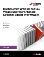
To enable VM mobility monitoring for the ITSO_VM_1 VIP, click the Application Management tab in the ARB plug-in window shown in Figure 4-13 on page 65.
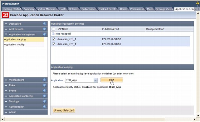
Figure 4-13 Brocade ARB configuration: Registering VIPs to a monitored application
The two virtual servers that you configured on the ADXs in Data Center A and Data Center B, dca-itso_vm_1 and dcb-itso_vm_1, are displayed as Not Mapped. Select both of these VIPs to map to the same application, because they have the same real server (VM) definition, which is ITSO_VM_1. Map both of them to ITSO_App, and then click Map.
After you finish this step, both virtual servers are mapped under ITSO_App, but vMotion Mobility is disabled. Right-click the application, and select Enable mobility, as shown in Figure 4-14.

Figure 4-14 Brocade ARB configuration: Enabling VM mobility for a mapped application
Finally, under the Application Mobility tab shown in Figure 4-15, check your configuration, and check which VIP is active and which VIP is backup.

Figure 4-15 Brocade ARB: Checking the Active/Backup VIP for a particular VM
4.2.6 Additional references
For more information, see the following manuals:
•Brocade ADX Administration Guide, Supporting v12.4.00
•Brocade ADX Server Load Balancing Guide, Supporting v12.4.00
•Brocade ADX Global Server Load Balancing Guide, Supporting v12.4.00
•Brocade ADX Application Resource Broker Administrator’s Guide for v2.0.0
4.3 IP networking configuration
There are several IP networking components that are used within this solution. End-to-end, data center network design is beyond the scope of this book. However, we cover the configuration of the switches as seen in the context of the setup.
Figure 4-16 shows the IP networking areas.

Figure 4-16 High-level IP network architecture
There are three IP networking components that we cover:
•Layer 2 switches: The ESXi hosts connect directly to Layer 2 switches. The Layer 2 network can be any standards-compliant switch, such as the IBM RackSwitch family of switches or the Brocade VDX series of switches. In a 3-tier network design, there is usually an edge made up of top-of-rack switches that connect to a higher density aggregation switch over Layer 2, running a type of Spanning Tree Protocol. With higher-density, top of rack switches, scalable logical switch capabilities, such as stacking or virtual switch clustering, and with passive patch paneling in each rack to a higher density end-of-row switch, the data center network might be collapsed into a flat Layer 2 edge that connects directly to the IP core over either Layer 2 or Layer 3.
•IP core: The Layer 2 network connects to the IP core, which then connects to the WAN edge and Internet. The configuration example connects from the Layer 2 switches to the IP core over Layer 2. The IP core is made up of Brocade MLXe devices that provide aggregation and routing capabilities among the various subnetworks.
•Brocade MLXe and CER acting as the data center interconnect or Provider Edge (PE) router: For the Layer 2 extension, the example uses standards-compliant L2 VPN technology that uses Multiprotocol Label Switching (MPL), Virtual Private LAN Service (VPLS), and Virtual Leased Line (VLL).
Figure 4-17 shows the actual lab configuration.

Figure 4-17 IBM SAN Volume Controller Stretched cluster lab architecture
A closer view of just the Data Center A (Site 1) connection is shown in Figure 4-18.

Figure 4-18 IBM SAN Volume Controller stretched cluster: Data Center A topology
The lab configuration example consists of these components:
•An IBM x3650 server that is the VMware ESXi host, esxi-01-dca1. This host has two 10 GbE ports and two 16 Gbps FC ports.
•The 16 Gbps FC ports that are connected to two separate IBM SAN768B-2 chassis, which form two separate, air -gapped FC SAN fabrics.
•The two 10 GbE ports are connected to two separate 10 GbE VDX switches. There are a total of four VDX switches in a Layer 2 network. These four VDX switches are clustered together by using VCS fabric technology. This configuration makes them look like a single logical switch to other network entities.
•VDX switches are then connected over Layer 2 to two MLXe routers that act as the IP core. The MLXe routers provide routing between the various subnetworks and aggregate the various connections.
•The Brocade ADX GSLB/SLB is connected to the MLXe.
•The data center interconnect links, which are Brocade CES routers, are connected to the MLXs. The Brocade CES routers provide the Layer 2 VPN extension capabilities by using VLL, acting as PE routers.
•The Brocade MLXe IP Core is also connected to simulated clients that might come in from the Internet, outside the data center.
•Also connected to the Brocade MLXe are two 10 GbE FCIP connections from each IBM SAN768B chassis. IBM SAN768B-A1 has two links that connect to DC1-Core1-MLX4. One link forms the Private SAN FCIP tunnel, and the second link forms the Public SAN FCIP tunnel. Similarly, IBM SAN768B-A2 has two links that are connected to DC1-Core2-MLX4.
4.3.1 Layer 2 switch configuration
The Layer 2 switch has the following configuration in this example.
Layer 2 loop prevention
Within the Layer 2 network, loop prevention is required. Typically a type of Spanning Tree protocol is used, usually either PVRSTP, MSTP, or RSTP depending on the environment. Consider the following guidelines when you select Spanning Tree configuration:
•Configure the Bridge Priority to ensure correct Root Bridge placement, which is typically at one of the Aggregation switches closest to the core.
•Configure switch-to-switch links as point-to-point, and edge ports that connect to the ESXi hosts as edge ports.
•Although the ESXi vSwitches do not run xSTP, leave xSTP enabled on the edge ports in case something is mis-wired in the future.
•Consider enabling BPDU guard on edge ports that face the ESXi hosts to prevent loops. Remember that this configuration cuts off access to all VMs behind that port if triggered.
VLAN configuration
VLANs must also be created for the various networks that vSphere and VMs use. As outlined in the Design Chapter, four VLANs must be defined all on switches in the Layer 2 network. This configuration is shown in Example 4-7.
Example 4-7 Defining VLANs on a switch
S1_RB4(config)# int vlan 700
S1_RB4(config-Vlan-700)# description Management
S1_RB4(config-Vlan-700)# int vlan 701
S1_RB4(config-Vlan-701)# description VM_Traffic
S1_RB4(config-Vlan-701)# int vlan 702
S1_RB4(config-Vlan-702)# description vMotion
S1_RB4(config-Vlan-702)# int vlan 703
S1_RB4(config-Vlan-703)# description Fault_Tolerant
The edge ports on the switch that is connected to the ESXi host and all traditional Ethernet links between switches must also be configured as VLAN trunk ports that allow VLANs 700-703. A configuration example is shown in Example 4-8.
Example 4-8 Configuring switch to ESXi host and switch-to-switch links to carry VLANs
S1_RB4(config)# int ten 4/0/15
S1_RB4(conf-if-te-4/0/15)# switchport
S1_RB4(conf-if-te-4/0/15)# switchport mode trunk
S1_RB4(conf-if-te-4/0/15)# switchport trunk allowed vlan add 700-703
Link Aggregation Group (LAG) configuration
In the example configuration, the ESXi uses the “route based on originating virtual port” load balancing. Therefore, a LAG does not need to be configured between the two switches that are connected to S1_RB3 and S1_RB4.
However, create a LAG between S1_RB1 and S1_RB2 to the two MLXs that acts as the IP Core. This configuration is possible because your four Layer 2 switches are in a single logical cluster, S1-VCS-1, using Virtual Cluster Switching (VCS) fabric technology. The two MLXs are also clustered together by using Brocade Multi-Chassis Trunking (MCT) technology.
To create a port-channel group on the switches in S1-VCS-1, place all four ports in the same port channel. Example 4-9 shows placing the ports on Switch S1_RB1.
Example 4-9 Switch S1_RB1: Placing ports connected to the core MLXs in channel-group 2
S1_RB1(config)# int ten 1/0/14
S1_RB1(conf-if-te-1/0/14)# channel-group 2 mode active type standard
S1_RB1(conf-if-te-1/0/14)# int ten 1/0/15
S1_RB1(conf-if-te-1/0/15)# channel-group 2 mode active type standard
Example 4-10 shows placing the ports on Switch S1_RB2.
Example 4-10 Switch S1_RB2: Placing ports connected to the core MLXs in channel-group 2
S1_RB1(config)# int ten 2/0/14
S1_RB1(conf-if-te-2/0/14)# channel-group 2 mode active type standard
S1_RB1(conf-if-te-2/0/14)# int ten 2/0/15
S1_RB1(conf-if-te-2/0/15)# channel-group 2 mode active type standard
Now that the port channels are created on both switches, specific the interface definitions at the port-channel level, as shown in the following examples. Example 4-11 shows Switch S1_RB1.
Example 4-11 Switch S1_RB1 - Interface Port-Channel 2 configuration
S1_RB1(config)# int port-channel 2
S1_RB1(config-Port-channel-2)# switchport
S1_RB1(config-Port-channel-2)# switchport mode trunk
S1_RB1(config-Port-channel-2)# switchport trunk allowed vlan add 701-703
Example 4-12 shows the configuration of Switch S1_RB2.
Example 4-12 Switch S1_RB2 - Interface Port-Channel 2 configuration
S1_RB2(config)# int port-channel 2
S1_RB2(config-Port-channel-2)# switchport
S1_RB2(config-Port-channel-2)# switchport mode trunk
S1_RB2(config-Port-channel-2)# switchport trunk allowed vlan add 701-703
Other considerations
The maximum transmission unit (MTU) size can be increased on all Layer 2 ports to support jumbo frames. This configuration can help with traffic efficiency when you are using IP-based storage or vMotion traffic. Configuration of jumbo frames can vary from switch to switch, from being a global to an interface-level command.
|
Remember: Make sure that the MTU size on all interfaces within the Layer 2 domain is the same, including for the ESXi host configuration. Otherwise, fragmentation might occur.
|
Keep these basic considerations in mind when you are setting up your network:
•Harden the switch by using role-based access control (or RBAC, for example, a RADIUS or TACACS+ server), user accounts, disabling Telnet, and restricting login to certain VLANs or IP ranges.
•Configure SNMP, Syslog, or sFlow monitoring servers.
•Configure a Network Time Protocol (NTP) server.
•Enable Link Layer Discovery Protocol (LLDP) and Cisco Discovery Protocol (CDP), or extra network visibility.
•Configure quality of service for specific traffic classes, or trusting the 802.1 p settings that are sent by ESXi.
•Configure security and access control lists.
Additional references
For more information about the Brocade VDX, see these manuals:
•Network OS Administrator’s Guide, Supporting v2.1.1
•Network OS Command Reference Manual, Supporting v2.1.1
4.3.2 IP Core (MLXe) configuration
Keep the following considerations in mind when you are configuring IP Core (MLXe):
VLAN configuration
Start by defining the VLANs that the MLXe carries traffic over. These are the same four VLANS, 700 – 703, defined in the Layer 2 switch network. However, the MLXe also carries the following FCIP traffic:
•VLAN 705 - Fabric A - Private SAN traffic
•VLAN 706 - Fabric A - Public SAN traffic
•VLAN 707 - Fabric B - Private SAN traffic
•VLAN 708 - Fabric B - Public SAN traffic
Within the lab topology, there are three different types of network traffic access patterns for traffic that passes through the MLXe.
Example 4-13 shows the different network traffic types and interfaces applicable on DC1-Core1-MLXe4:
•Traffic that needs access to only the “internal” network. These are ports that are connected to the Layer 2 network (eth 1/4, eth 2/4), the MCT link between the two MLXes (eth 1/1, eth 2/1), and the data center interconnect link to the CES (eth 2/5). Traffic types that fall into this category are the management, vMotion, and fault-tolerant traffic. Although the management traffic might need to be routed to a different subnetwork (which is why you create a virtual interface in that VLAN), the vMotion and fault-tolerant traffic should never need to be routed.
•Traffic that needs access to the “internal” network, the external client traffic (eth 1/6), and the ADX GSLB/SLB (eth 1/7). This is the VM traffic that might also need to be routed.
•FCIP traffic that requires access to directly connected IBM SAN768B-2 (eth 1/3, eth 2/6), the MCT link between the two MLXs (eth 1/1, eth 2/1), and the data center interconnect link to the CES (eth 2/5).
An example of creating these VLANs and tagging the appropriate interfaces is shown in Example 4-13.
Example 4-13 Creating VLANs and virtual routing interfaces on DC1-Core1-MLXe4
telnet@DC1-Core1-MLXe(config)#vlan 700 name I-MGMT
telnet@DC1-Core1-MLXe(config-vlan-700)#tag eth 1/1 eth 1/4 eth 2/1 eth 2/4 to 2/5
telnet@DC1-Core1-MLXe(config-vlan-700)#router-interface ve 70
telnet@DC1-Core1-MLXe(config-vlan-700)#vlan 701 name I-VM_Traffic
telnet@DC1-Core1-MLXe(config-vlan-701)#tag ethe 1/1 eth 1/4 eth 1/6 to 1/7 eth 2/1 eth 2/4 to 2/5
telnet@DC1-Core1-MLXe(config-vlan-701)#router-interface ve 71
telnet@DC1-Core1-MLXe(config-vlan-701)#vlan 702 name I-vMotion
telnet@DC1-Core1-MLXe(config-vlan-702)#tag eth 1/1 eth 1/4 eth 2/1 eth 2/4 to 2/5
telnet@DC1-Core1-MLXe(config-vlan-702)#vlan 703 name I-Fault_Tolerant
telnet@DC1-Core1-MLXe(config-vlan-703)#tag ethe 1/1 eth 1/4 eth 1/6 to 1/7 eth 2/1 eth 2/4 to 2/5
telnet@DC1-Core1-MLXe(config-vlan-703)#vlan 705 name I-FCIP-Priv-FabA
telnet@DC1-Core1-MLXe(config-vlan-705)#untag eth 1/3
telnet@DC1-Core1-MLXe(config-vlan-705)#tag eth 1/1 eth 2/1 eth 2/5
telnet@DC1-Core1-MLXe(config-vlan-705)#vlan 706 name I-FCIP-Pub-FabA
telnet@DC1-Core1-MLXe(config-vlan-706)#untag eth 2/6
telnet@DC1-Core1-MLXe(config-vlan-706)#tag ethe 1/1 ethe 2/1 ethe 2/5
telnet@DC1-Core1-MLXe(config-vlan-706)#vlan 707 name I-FCIP-Priv-FabB
telnet@DC1-Core1-MLXe(config-vlan-707)#tag ethe 1/1 ethe 2/1 ethe 2/5
telnet@DC1-Core1-MLXe(config-vlan-707)#vlan 708 name I-FCIP-Pub-FabB
telnet@DC1-Core1-MLXe(config-vlan-708)#tag ethe 1/1 ethe 2/1 ethe 2/5
The connection to the data center interconnects, DC1-DCI1-CER and DC1-DCI2-CER, are simply a Layer 2 link. In this configuration, the MLXes are acting as the Customer Edge routers, whereas the CER is configured with MPLS and VLL acting as the Provider Edge routers.
VRRPe: Layer 3 gateway configuration
Each VLAN that requires routing has a virtual router interface created. The Management VLAN has ve 70 created and the VM Traffic VLAN ve 71 within those VLANs. These virtual interfaces must be configured with an IP address to route traffic. The example uses Virtual Router Redundancy Protocol-Extended (VRRPe) to provide active-active Layer 3 gateways for your VMs on each of those virtual routing interfaces.
A VRRPe instance (VRID) is created with a single VIP that VMs use as their gateway address. Within the VRID, one or more router interfaces are also configured as the actual paths that traffic passes through. With VRRPe, all router interfaces within a VRID can route traffic instead of having to be switched through a single designated Master interface in the case of regular VRRP.
Example 4-14 shows how to enable VRRPe on a router.
Example 4-14 Enabling the VRRPe protocol on a router
telnet@DC1-Core1-MLXe(config)#router vrrp-extended
telnet@DC1-Core1-MLXe(config-vrrpe-router)#exit
telnet@DC1-Core1-MLXe(config)#
An IP address must be configured for interface ve 70, in this case 192.168.200.250/24. Next, configure VRRPe and select an arbitrary VRID value of 70. In the context of VRRPe, all VRRPe interfaces are designated as backup interfaces. There is no one Master interface. The VIP of the VRID is also defined, in this case 192.168.200.1. Finally, enable short-path-forwarding, which allows any VRRPe interface to route traffic instead of having to switch to a designated Master interface. Finally, activate the VRRPe configuration.
Example 4-15 shows how to configure VRRPe on interface ve 70 on DC1-Core1-MLXe.
Example 4-15 Configuring VRRPe on DC1-Core1-MLXe4, interface ve 70
telnet@DC1-Core1-MLXe(config)#interface ve 70
telnet@DC1-Core1-MLXe(config-vif-70)#port-name I-Internal-Mgmt
telnet@DC1-Core1-MLXe(config-vif-70)#ip address 192.168.200.250/24
telnet@DC1-Core1-MLXe(config-vif-70)#ip vrrp-extended vrid 70
telnet@DC1-Core1-MLXe(config-vif-70-vrid-70)#backup
telnet@DC1-Core1-MLXe(config-vif-70-vrid-70)#advertise backup
telnet@DC1-Core1-MLXe(config-vif-70-vrid-70)#ip-address 192.168.200.1
telnet@DC1-Core1-MLXe(config-vif-70-vrid-70)#short-path-forwarding
telnet@DC1-Core1-MLXe(config-vif-70-vrid-70)#activate
A similar configuration can be done on DC1-Core2-MLXe4, and the two routers in Data Center B, DC2-Core1-MLXe16 and DC2-Core2-MLXe4. A different/unique IP address for each virtual interface on those routers must be selected, although the VRRPe VRID and VIP remain the same.
Example 4-16 on page 75 shows how to configure DC1-Core2-MLXe4.
Example 4-16 Configuring VRRPe on DC1-Core2-MLXe4, interface ve 70
telnet@DC1-Core2-MLXe(config)#interface ve 70
telnet@DC1-Core2-MLXe(config-vif-70)#port-name I-Internal-Mgmt
telnet@DC1-Core2-MLXe(config-vif-70)#ip address 192.168.200.251/24
telnet@DC1-Core2-MLXe(config-vif-70)#ip vrrp-extended vrid 70
telnet@DC1-Core2-MLXe(config-vif-70-vrid-70)#backup
telnet@DC1-Core2-MLXe(config-vif-70-vrid-70)#advertise backup
telnet@DC1-Core2-MLXe(config-vif-70-vrid-70)#ip-address 192.168.200.1
telnet@DC1-Core2-MLXe(config-vif-70-vrid-70)#short-path-forwarding
telnet@DC1-Core2-MLXe(config-vif-70-vrid-70)#activate
A third example configuration of DC2-Core1-MLXe16 is shown in Example 4-17.
Example 4-17 Configuring VRRPe on DC2-Core1-MLXe16, interface ve 70
telnet@DC1-Core2-MLXe(config)#interface ve 70
telnet@DC1-Core2-MLXe(config-vif-70)#port-name I-Internal-Mgmt
telnet@DC1-Core2-MLXe(config-vif-70)#ip address 192.168.200.252/24
telnet@DC1-Core2-MLXe(config-vif-70)#ip vrrp-extended vrid 70
telnet@DC1-Core2-MLXe(config-vif-70-vrid-70)#backup
telnet@DC1-Core2-MLXe(config-vif-70-vrid-70)#advertise backup
telnet@DC1-Core2-MLXe(config-vif-70-vrid-70)#ip-address 192.168.200.1
telnet@DC1-Core2-MLXe(config-vif-70-vrid-70)#short-path-forwarding
telnet@DC1-Core2-MLXe(config-vif-70-vrid-70)#activate
MCT Trunking configuration
The two MLXes are also configured together in an MCT cluster. First, create a LAG of two ports between DC1-Core1-MLX4 and DC1-Core2-MLX4 over ports eth 1/1 and eth 2/1 to use as the MCT Inter-Chassis Link (ICL). Example 4-18 shows an example of a static LAG configuration from the DC1-Core1-MLX4 chassis. Do similar configuration on the DC1-Core2-MLX4.
Example 4-18 MLXe: Creating a static LAG
telnet@DC1-Core1-MLXe(config)#lag "ICL" static id 1
telnet@DC1-Core1-MLXe(config-lag-ICL1)#ports eth 1/1 eth 2/1
telnet@DC1-Core1-MLXe(config-lag-ICL1)#primary-port 1/1
telnet@DC1-Core1-MLXe(config-lag-ICL1)#deploy
telnet@DC1-Core1-MLXe(config-lag-ICL1)#port-name "ICL" ethernet 1/1
telnet@DC1-Core1-MLXe(config-lag-ICL1)#port-name "ICL" ethernet 2/1
telnet@DC1-Core1-MLXe(config-lag-ICL1)#int eth 1/1
telnet@DC1-Core1-MLXe(config-if-e10000-1/1)#enable
After the LAG is created and up between the two MLXes, configure a VLAN along with a virtual router interface to carry MCT cluster communication traffic, as shown in Example 4-19.
Example 4-19 Creating a VLAN for MCT cluster communication traffic
telnet@DC1-Core1-MLXe(config)#vlan 4090 name MCT_SESSION_VLAN
telnet@DC1-Core1-MLXe(config-vlan-4090)#tag ethe 1/1
telnet@DC1-Core1-MLXe(config-vlan-4090)#router-interface ve 1
|
Tip: Only the 1/1 must be tagged, because that is the primary port in the LAG.
|
Next, configure the virtual routing interface with an IP address that the two MLXes use for MCT cluster communication, as shown in Example 4-20.
Example 4-20 Assigning an IP address to a virtual routing interface
telnet@DC1-Core1-MLXe(config)#interface ve 1
telnet@DC1-Core1-MLXe(config-vif-1)#port-name MCT-Peer
telnet@DC1-Core1-MLXe(config-vif-1)#ip address 1.1.1.1/24
Finally, configure the cluster as shown in Example 4-21. More details about each step can be found in the Brocade MLXe Configuration Guide.
Example 4-21 Completing the MCT cluster configuration
telnet@DC1-Core1-MLXe(config)#cluster MCT_CLUSTER 1
telnet@DC1-Core1-MLXe(config-cluster-MCT_CLUSTER)#rbridge-id 10
telnet@DC1-Core1-MLXe(config-cluster-MCT_CLUSTER)#session-vlan 4090
telnet@DC1-Core1-MLXe(config-cluster-MCT_CLUSTER)#member-vlan 100 to 999
telnet@DC1-Core1-MLXe(config-cluster-MCT_CLUSTER)#icl ICL ethernet 1/1
telnet@DC1-Core1-MLXe(config-cluster-MCT_CLUSTER)#peer 1.1.1.2 rbridge-id 20 icl ICL
telnet@DC1-Core1-MLXe(config-cluster-MCT_CLUSTER)#deploy
telnet@DC1-Core1-MLXe(config-cluster-MCT_CLUSTER)#client DC1-SLB1-ADX
telnet@DC1-Core1-MLXe(config-cluster-MCT_CLUSTER-client-DC1-SLB1-ADX)#rbridge-id 100
telnet@DC1-Core1-MLXe(config-cluster-MCT_CLUSTER-client-DC1-SLB1-ADX)#client-interface ethernet 1/7
telnet@DC1-Core1-MLXe(config-cluster-MCT_CLUSTER-client-DC1-SLB1-ADX)#deploy
telnet@DC1-Core1-MLXe(config-cluster-MCT_CLUSTER-client-DC1-SLB1-ADX)#exit
telnet@DC1-Core1-MLXe(config-cluster-MCT_CLUSTER)#client VCS1
telnet@DC1-Core1-MLXe(config-cluster-MCT_CLUSTER-client-VCS1)#rbridge-id 200
telnet@DC1-Core1-MLXe(config-cluster-MCT_CLUSTER-client-VCS1)#client-interface ethernet 1/4
telnet@DC1-Core1-MLXe(config-cluster-MCT_CLUSTER-client-VCS1)#deploy
telnet@DC1-Core1-MLXe(config-cluster-MCT_CLUSTER-client-VCS1)#exit
telnet@DC1-Core1-MLXe(config-cluster-MCT_CLUSTER)#client CER_DCI
telnet@DC1-Core1-MLXe(config-cluster-MCT_CLUSTER-client-CER_DCI)#rbridge-id 300
telnet@DC1-Core1-MLXe(config-cluster-MCT_CLUSTER-client-CER_DCI)#client-interface ethernet 2/5
telnet@DC1-Core1-MLXe(config-cluster-MCT_CLUSTER-client-CER_DCI)#deploy
Other considerations
The Brocade MLXe routers are high-performance routers that are capable of handling the entire Internet routing table, with advanced MPLS, VPLS, VLL features and other high-end service provider-grade capabilities. However, it is beyond the scope of this book to address IP network design, routing protocols, and so on.
Additional references
For more information about the Brocade MLXe, see the Brocade MLX Series and NetIron Family Configuration Guide, Supporting r05.3.00 or the product web page:
4.3.3 Data Center Interconnect (CER) configuration
The Layer 2 network must be extended from Data Center A to Data Center B to support VM mobility. This configuration can be done by using a Layer 2 VPN technology that uses standards-based MPLS, VPLS, or VLL technology. This is typically provided by the service provider.
However, in some situations, it is beneficial to extend the Layer 2 VPN deeper into the data center. For example, two data centers that are connected point-to-point over dark fiber and MPLS can be used for advanced QoS control or other purposes. The Brocade MLXe chassis and Brocade NetIron CER 1 RU switches both support MPLS, VPLS, or VLL capabilities.
It is beyond the scope of this book to address this technology, because it is complex. However, the configurations between two of the CER interconnects in the lab setup are shown for reference in Example 4-22 and Example 4-23 on page 78.
Example 4-22 DC1-DCI1-CER configuration
router ospf
area 0
!
interface loopback 1
ip ospf area 0
ip address 80.80.80.10/32
!
interface ethernet 2/1
enable
ip ospf area 0
ip ospf network point-to-point
ip address 200.10.10.1/30
!
interface ethernet 2/2
enable
!
router mpls
mpls-interface e1/1
ldp-enable
mpls-interface e2/1
ldp-enable
vll DCIvl700 700
vll-peer 90.90.90.10
vlan 700
tagged e 2/2
vll DCIvl701 701
vll-peer 90.90.90.10
vlan 701
tagged e 2/2
vll DCIvl702 702
vll-peer 90.90.90.10
vlan 702
tagged e 2/2
vll DCIvl703 703
vll-peer 90.90.90.10
vlan 703
tagged e 2/2
vll DCIvl705 705
vll-peer 90.90.90.10
vlan 705
tagged e 2/2
vll DCIvl706 706
vll-peer 90.90.90.10
vlan 706
tagged e 2/2
vll DCIvl707 707
vll-peer 90.90.90.10
vlan 707
tagged e 2/2
vll DCIvl708 708
vll-peer 90.90.90.10
vlan 708
tagged e 2/2
Example 4-23 shows the configuration of SC2-CDCI1-CER in the lab environment.
Example 4-23 DC2-DCI1-CER configuration
router ospf
area 0
!
interface loopback 1
ip ospf area 0
ip address 90.90.90.10/32
!
interface ethernet 2/1
enable
ip ospf area 0
ip ospf network point-to-point
ip address 200.10.10.2/30
!
interface ethernet 2/2
enable
!
router mpls
mpls-interface e1/1
ldp-enable
mpls-interface e2/1
ldp-enable
vll DCIvl700 700
vll-peer 80.80.80.10
vlan 700
tagged e 2/2
vll DCIvl701 701
vll-peer 80.80.80.10
vlan 701
tagged e 2/2
vll DCIvl702 702
vll-peer 80.80.80.10
vlan 702
tagged e 2/2
vll DCIvl703 703
vll-peer 80.80.80.10
vlan 703
tagged e 2/2
vll DCIvl705 705
vll-peer 80.80.80.10
vlan 705
tagged e 2/2
vll DCIvl706 706
vll-peer 80.80.80.10
vlan 706
tagged e 2/2
vll DCIvl707 707
vll-peer 80.80.80.10
vlan 707
tagged e 2/2
vll DCIvl708 708
vll-peer 80.80.80.10
vlan 708
tagged e 2/2
For more information about the Brocade CER, see the Brocade MLX Series and NetIron Family Configuration Guide, Supporting r05.3.00.
4.4 IBM Fibre Channel SAN
The following section is based on the assumption that you are familiar with general Fibre Channel (FC) SAN design and technologies. Typically, the SAN design has servers and storage that are connected into dual, redundant fabrics. The lab configuration has a redundant fabric design that uses two IBM SAN768B-2 chassis at each data center site. Each IBM SAN768B-2 is equipped with these components:
•IBM FC 8 Gbps Fibre Channel over IP (FCIP) Extension blade in Slot 1
•IBM FC 16 Gbps 48-port blade in Slot 8
IBM SAN Volume Controller enhanced stretched cluster (ESC) requires two types of SAN:
•Public SAN: In this type, server hosts, storage, and SAN Volume Controller nodes connect. Data storage traffic traverses the Public SAN.
•Private SAN: Only the SAN Volume Controller nodes connect into the Private SAN, which is used for cluster communication.
Each IBM SAN768B-2 is split into two logical chassis to implement segregated private and public SANs on the same chassis. Figure 4-19 shows the various public and private SAN connections, with each in a different color.

Figure 4-19 Public and private SAN connections at each data center site
Figure 4-20 on page 81 shows the actual lab environment.

Figure 4-20 IBM SAN Volume Controller stretched cluster lab topology
4.4.1 Creating the logical switches
Configure a total of four fabrics, each with two different logical switches.
Figure 4-21 shows a closer picture of the SAN port topology in Data Center A.
Figure 4-21 Data Center A: SAN port topology
Figure 4-22 on page 82 shows a closer picture of the SAN port topology in Data Center B.

Figure 4-22 Data Center B: SAN port topology
Next, create logical switches on the SAN768B-2s and map them according to Table 4-1.
Table 4-1 Fabric to physical switch to logical switch mappings
|
Fabric name
|
Physical switch
|
Logical switch
|
LS #
|
Ports
|
|
Fabric-Public-1
|
SAN768B-2_A1
|
Public_A1
|
111
|
1/12, 8/2, 8/4, 8/5, 8/6, 8/7, 8/8, 8/9, 8/10
|
|
SAN768B-2_B1
|
Public_B1
|
1/12, 8/0, 8/1, 8/2, 8/4, 8/5, 8/6, 8/7, 8/8, 8/9
|
||
|
Fabric-Public-2
|
SAN768B-2_A2
|
Public_A2
|
113
|
1/12, 8/2, 8/4, 8/5, 8/6, 8/7, 8/8, 8/9, 8/10
|
|
SAN768B-2_B2
|
Public_B2
|
1/12, 8/0, 8/1, 8/2, 8/4, 8/5, 8/6, 8/7, 8/8, 8/9
|
||
|
Fabric-Private-1
|
SAN768B-2_A1
|
Private_A1
|
112
|
1/22, 8/3
|
|
SAN768B-2_B1
|
Private_B1
|
1/22, 8/3
|
||
|
Fabric-Private-2
|
SAN768B-2_A2
|
Private_A2
|
114
|
1/22, 8/3
|
|
SAN768B-2_B2
|
Private_B2
|
1/22, 8/3
|
1/12 corresponds to one of the FCIP tunnels on 1/xge0, whereas 1/22 corresponds to one of the FCIP tunnels on 1/xge1.
Two examples of creating a logical switch through the CLI and through IBM Network Advisor follow. For more information about creating virtual fabrics, see the IBM Redbooks publication titled Implementing an IBM b-type SAN with 8 Gbps Directors and Switches, SG24-6116.
Example 4-24 shows creating the Public_A1 on SAN768B-2_A1 logical switch.
Example 4-24 Creating the Public_A1 logical switch
SAN768B-2_A1:FID128:admin> lscfg --create 111
About to create switch with fid=111. Please wait...
Logical Switch with FID (111) has been successfully created.
Logical Switch has been created with default configurations.
Please configure the Logical Switch with appropriate switch
and protocol settings before activating the Logical Switch.
SAN768B-2_A1:FID128:admin> lscfg --config 111 -slot 1 -port 12
This operation requires that the affected ports be disabled.
Would you like to continue [y/n]?: y
Making this configuration change. Please wait...
Configuration change successful.
Please enable your ports/switch when you are ready to continue.
SAN768B-2_A1:FID128:admin> lscfg --config 111 -slot 8 -port 2
This operation requires that the affected ports be disabled.
Would you like to continue [y/n]?: y
Making this configuration change. Please wait...
Configuration change successful.
Please enable your ports/switch when you are ready to continue.
SAN768B-2_A1:FID128:admin> lscfg --config 111 -slot 8 -port 4-10
This operation requires that the affected ports be disabled.
Would you like to continue [y/n]?: y
Making this configuration change. Please wait...
Configuration change successful.
Please enable your ports/switch when you are ready to continue.
SAN768B-2_A1:FID128:admin> setcontext 111
Please change passwords for switch default accounts now.
Use Control-C to exit or press 'Enter' key to proceed.
Password was not changed. Will prompt again at next login
until password is changed.
switch_111:FID111:admin> switchname Public_A1
Done.
switch_111:FID111:admin>
switch_111:FID111:admin> setcontext 128
Please change passwords for switch default accounts now.
Use Control-C to exit or press 'Enter' key to proceed.
Password was not changed. Will prompt again at next login
until password is changed.
SAN768B-2_A1:FID128:admin> setcontext 111
Please change passwords for switch default accounts now.
Use Control-C to exit or press 'Enter' key to proceed.
Password was not changed. Will prompt again at next login
until password is changed.
Public_A1:FID111:admin> switchshow
switchName: Public_A1
switchType: 121.3
switchState: Online
switchMode: Native
switchRole: Principal
switchDomain: 1
switchId: fffc01
switchWwn: 10:00:00:05:33:b5:3e:01
zoning: OFF
switchBeacon: OFF
FC Router: OFF
Allow XISL Use: ON
LS Attributes: [FID: 111, Base Switch: No, Default Switch: No, Address Mode 0]
Index Slot Port Address Media Speed State Proto
=======================================================
12 1 12 01fcc0 -- -- Offline VE Disabled
194 8 2 01cf40 id N16 In_Sync FC Disabled
196 8 4 01cec0 id N16 In_Sync FC Disabled
197 8 5 01ce80 id N16 In_Sync FC Disabled
198 8 6 01ce40 id N16 In_Sync FC Disabled
199 8 7 01ce00 id N16 In_Sync FC Disabled
200 8 8 01cdc0 id N16 In_Sync FC Disabled
201 8 9 01cd80 id N16 In_Sync FC Disabled
202 8 10 01cd40 id N16 In_Sync FC Disabled
Public_A1:FID111:admin> switchenable
Public_A1:FID111:admin> switchshow
switchName: Public_A1
switchType: 121.3
switchState: Online
switchMode: Native
switchRole: Principal
switchDomain: 1
switchId: fffc01
switchWwn: 10:00:00:05:33:b5:3e:01
zoning: OFF
switchBeacon: OFF
FC Router: OFF
Allow XISL Use: ON
LS Attributes: [FID: 111, Base Switch: No, Default Switch: No, Address Mode 0]
Index Slot Port Address Media Speed State Proto
=======================================================
12 1 12 01fcc0 -- -- Offline VE
194 8 2 01cf40 id N8 Online FC F-Port 50:05:07:68:01:40:b1:3f
196 8 4 01cec0 id N8 Online FC F-Port 50:05:07:68:02:10:00:ef
197 8 5 01ce80 id N8 Online FC F-Port 50:05:07:68:02:20:00:ef
198 8 6 01ce40 id N8 Online FC F-Port 50:05:07:68:02:10:00:f0
199 8 7 01ce00 id N8 Online FC F-Port 50:05:07:68:02:20:00:f0
200 8 8 01cdc0 id N8 Online FC F-Port 50:05:07:68:02:10:05:a8
201 8 9 01cd80 id N8 Online FC F-Port 50:05:07:68:02:10:05:a9
202 8 10 010000 id N16 Online FC F-Port 10:00:8c:7c:ff:0a:d7:00
Public_A1:FID111:admin>
The next example shows creating the Public_B1 on SAN768B-2_B1 logical switch by using the IBM Network Advisor software management tool.
First, find the Chassis Group that represents the discovered physical switches for SAN768B-2_B1. Right-click the switch, and select Configuration → Logical Switches, as shown in Figure 4-23.

Figure 4-23 Entering the Logical Switches configuration menu
|
Clarification: In Figure 4-23, most of the logical switches are already created and the fabrics discovered. However, Fabric-Public-1 was re-created as an example. Logical switch Public_A1 in Data Center A was already created. It is a single-switch fabric that is named Fabric-Public-1A.
|
In the Logical Switches window, check to make sure that the chassis that you selected is SAN768B-2_B1. Then, select Undiscovered Logical Switches in the right window, and click New Switch, as shown in Figure 4-24 on page 86.

Figure 4-24 Creating a new logical switch on SAN768B-2_B1
In the New Logical Switch window, set the Logical Fabric ID to 111. This configuration is chassis-local. It does not have to be the same as the Public_A1 switch that it eventually merges with. However, set it the same for consistency. This process is shown in Figure 4-25.

Figure 4-25 Setting the Logical Fabric ID
Next, click the Switch tab and provide a switch name of Public_B1, as shown in Figure 4-26 on page 87.

Figure 4-26 Setting the switch name for Public_B1
Now that the new logical switch construct is created, move the ports from SAN768B-2_B1 to Public_B1, as shown in Figure 4-27.

Figure 4-27 Selecting the ports from SAN768B-2_B1 to move to logical switch Public_B1
Review the information in the confirmation window, and then click Start to begin the process. Figure 4-28 on page 88 shows the message that confirms the creation.

Figure 4-28 Successfully creating Public_B1
The new switch has not been discovered yet. Go to the Discovery menu and start a discovery on SAN768B-2_B1 to add the new logical switch as a monitored switch in the fabric. The IP address for SAN768B-2_B1 is a previously discovered IP address, so select it as shown in Figure 4-29.

Figure 4-29 Rediscovering SAN768B-2_B1 to add Public_B1
In the Fabric Discovery window, name the new fabric Fabric-Public-1B, for now, as shown in Figure 4-30 on page 89.

Figure 4-30 Discovering Fabric-Public-1B
Choose to discover and monitor only Public_B1, not the base SAN768B-2_B1 switch, as shown in Figure 4-31.

Figure 4-31 Selecting to monitor only Public_B1
Fabric-Public-1B with Public_B1 is now visible in the SAN view, as shown in Figure 4-32 on page 90.

Figure 4-32 Fabric-Public-1B successfully discovered
4.4.2 Creating FCIP tunnels
This section explains how to create the FCIP tunnel connectivity through the command-line interface (CLI). For more information, see IBM System Storage b-type Multiprotocol Routing: An Introduction and Implementation, SG24-7544
An FCIP tunnel or FCIP trunk is a single logical ISL, or VE_port. On the IBM FC 8 Gbps FCIP Extension blade, an FCIP tunnel can have one or more circuits. A circuit is an FCIP connection between two unique IP addresses.
Complete these steps to create an FCIP tunnel manually:
1. Create an IP interface on the physical Ethernet port. This process is done in the default switch context.
2. Validate connectivity between the SAN768B-2 chassis IP interfaces by using ping.
3. Within the logical switch that the VE_port belongs to, create an FCIP tunnel off of the IP interface that was created in the default switch context.
First, create the IP interface on Public_A1 by using interface 1/xge1, which VE_port 1/12 can use. Create an IP interface with an IP address of 192.168.76.10, netmask 255.255.255.0, with an MTU of 1500 bytes as shown in Example 4-25.
Example 4-25 Creating the IP interface on Public_A1
SAN768B-2_A1:FID128:admin> portcfg ipif 1/xge1 create 192.168.76.10 255.255.255.0 1500
Operation Succeeded
Create a similar interface but with an IP address of 192.168.76.20/24 on Public_B1, as shown in Example 4-26 on page 91.
Example 4-26 Creating the IP interface on Public_B1
SAN768B-2_B1:FID128:admin> portcfg ipif 1/xge1 create 192.168.76.20 255.255.255.0 1500
Operation Succeeded
Run validation tests from Public_A1 to make sure that connectivity through these interfaces works as shown in Example 4-27.
Example 4-27 Validating IP connectivity between Public_A1 and Public_B1
SAN768B-2_A1:FID128:admin> portcmd --ping 1/xge1 -s 192.168.76.10 -d 192.168.76.20
Pinging 192.168.76.20 from ip interface 192.168.76.10 on 1/xge1 with 64 bytes of data
Reply from 192.168.76.20: bytes=64 rtt=2ms ttl=20
Reply from 192.168.76.20: bytes=64 rtt=0ms ttl=20
Reply from 192.168.76.20: bytes=64 rtt=0ms ttl=20
Reply from 192.168.76.20: bytes=64 rtt=0ms ttl=20
Ping Statistics for 192.168.76.20:
Packets: Sent = 4, Received = 4, Loss = 0 ( 0 percent loss)
Min RTT = 0ms, Max RTT = 2ms Average = 0ms
SAN768B-2_A1:FID128:admin> portcmd --traceroute 1/xge1 -s 192.168.76.10 -d 192.168.76.20
Traceroute to 192.168.76.20 from IP interface 192.168.76.10 on 1/xge1, 30 hops max
1 192.168.76.20 0 ms 0 ms 0 ms
Traceroute complete.
Now that basic IP connectivity is established, change your logical switch context to 111, where VE_port 1/12 is, to create the FCIP tunnel. Set a minimum bandwidth of 622 Kbps and turn on compression with standard settings, as shown in Example 4-28 on page 92.
|
Tip: FastWrite is not needed because IBM SAN Volume Controller uses a different algorithm to improve transfer over distance. IPSec is also supported and can be turned on if needed.
|
Example 4-28 Creating the FCIP tunnel on Public_A1
SAN768B-2_A1:FID128:admin> setcontext 111
Please change passwords for switch default accounts now.
Use Control-C to exit or press 'Enter' key to proceed.
Password was not changed. Will prompt again at next login
until password is changed.
Public_A1:FID111:admin> portcfg fciptunnel 1/12 create 192.168.76.20 192.168.76.10 -b 622000 -B 1000000 -c 1
Operation Succeeded
Public_A1:FID111:admin> portcfgshow fciptunnel 1/12
-------------------------------------------
Tunnel ID: 1/12
Tunnel Description:
Compression: On (Standard)
Fastwrite: Off
Tape Acceleration: Off
TPerf Option: Off
IPSec: Disabled
QoS Percentages: High 50%, Med 30%, Low 20%
Remote WWN: Not Configured
Local WWN: 10:00:00:05:33:b5:3e:01
Flags: 0x00000000
FICON: Off
Public_A1:FID111:admin> portcfgshow fcipcircuit 1/12
-------------------------------------------
Circuit ID: 1/12.0
Circuit Num: 0
Admin Status: Enabled
Connection Type: Default
Remote IP: 192.168.76.20
Local IP: 192.168.76.10
Metric: 0
Min Comm Rt: 622000
Max Comm Rt: 1000000
SACK: On
Min Retrans Time: 100
Max Retransmits: 8
Keepalive Timeout: 10000
Path MTU Disc: 0
VLAN ID: (Not Configured)
L2CoS: (VLAN Not Configured)
DSCP: F: 0 H: 0 M: 0 L: 0
Flags: 0x00000000
Public_A1:FID111:admin>
Finally, configure an FCIP tunnel on Public_B1 with the same settings, and verify that the tunnel was established, as seen in Example 4-29.
Example 4-29 Creating an FCIP tunnel on Public_B1 and verifying that it is established
SAN768B-2_B1:FID128:admin> setcontext 111
Please change passwords for switch default accounts now.
Use Control-C to exit or press 'Enter' key to proceed.
Password was not changed. Will prompt again at next login
until password is changed.
Public_B1:FID111:admin> portcfg fciptunnel 1/12 create 192.168.76.10 192.168.76.20 -b 622000 -B 1000000 -c 1
Operation Succeeded
Public_B1:FID111:admin> portshow fcipcircuit all
-------------------------------------------------------------------------------
Tunnel Circuit OpStatus Flags Uptime TxMBps RxMBps ConnCnt CommRt Met
-------------------------------------------------------------------------------
1/12 0 1/xge1 Up ---4--s 1m27s 0.00 0.00 1 622/1000 0
-------------------------------------------------------------------------------
Flags: circuit: s=sack v=VLAN Tagged x=crossport 4=IPv4 6=IPv6
L=Listener I=Initiator
Public_B1:FID111:admin>
4.5 SAN Volume Controller with an enhanced stretched cluster
The IBM SAN Volume Controller code that is used is based on code level 7.2.0.0, and the back-end storage that is used in the example is a Storwize V7000 running a code level of 7.2.0.0. The third site, the quorum storage, is on a Storwize V7000 running a code level of 7.2.0.0
Be sure to check the full list of supported extended quorum devices:
V7.1.x Supported Hardware List, Device Driver, Firmware and Recommended Software Levels for SAN Volume Controller.
Figure 4-33 on page 94 shows the components that are used for the SAN Volume Controller stretched cluster with SAN connectivity.

Figure 4-33 SAN Volume Controller stretched cluster diagram with SAN connectivity
This book does not cover the physical installation nor the initial configuration. It supplements the Techdoc titled IBM SAN Volume Controller 7.1 SVC cluster spanning multiple data centers (Stretched Cluster / Split I/O group):
The information in this book is based on the assumption that you are familiar with the major concepts of SAN Volume Controller clusters, such as nodes, I/O groups, MDisks, and quorum disks.
If you are not, see the IBM Redbooks publication titled Implementing the IBM System Storage SAN Volume Controller V6.3, SG24-7933.
Also see the IBM SAN Volume Controller Information Center:
4.6 SAN Volume Controller volume mirroring
The ESC I/O group uses SAN Volume Controller volume mirroring functionality. Volume mirroring allows creation of one volume with two copies of MDisk extents. In this configuration, there are not two volumes with the same data on them. The two data copies can be in different MDisk groups. Therefore, volume mirroring can minimize the impact to volume availability if one or more MDisks fails. The resynchronization between both copies is incremental. SAN Volume Controller starts the resynchronization process automatically.
A mirrored volume has the same functions and behavior as a standard volume. In the SAN Volume Controller software stack, volume mirroring is below the cache and copy services. Therefore, FlashCopy, Metro Mirror, and Global Mirror have no awareness that a volume is mirrored. Everything that can be done with a volume can also be done with a mirrored volume, including migration and expand or shrink. Like a standard volume, each mirrored volume is owned by one I/O group with a preferred node, so the mirrored volume goes offline if the whole I/O group goes offline. The preferred node runs all I/O operations, reads, and writes. The preferred node can be set manually.
The three quorum disk candidates keep the status of the mirrored volume. The last status and the definition of primary and secondary volume copy (for read operations) are saved there. This means that an active quorum disk is required for volume mirroring. To ensure data consistency, SAN Volume Controller disables mirrored volumes if there is no access to any quorum disk candidate. Therefore, quorum disk availability is an important point with volume mirroring and split I/O group configuration. Furthermore, you must allocate bitmap memory space before using volume mirroring. Use the chiogrp command:
chiogrp -feature mirror -size memory_size io_group_name|io_group_id
The volume mirroring grain size is fixed at 256 KB, so one bit of the synchronization bitmap represents 256 KB of virtual capacity. Therefore, bitmap memory space of 1 MB is required for each 2 TB of mirrored volume capacity.
4.7 Read operations
Since SAN Volume Controller Version 7.1, volume mirroring implements a read algorithm with one copy that is designated as the primary for all read operations. SAN Volume Controller reads the data from the primary copy and does not automatically distribute the read requests across both copies. The first copy that is created becomes the primary by default. You can change this setting by using the chvdisk command:
chvdisk -primary copyid vdiskname
Starting with SAN Volume Controller Version 7.2 read operations can be run from either node in the I/O group. However, all read operations run to the local site copy if both sites are in sync.
4.8 Write operations
Write operations are run on all copies. The storage system with the lowest performance determines the response time between SAN Volume Controller and the storage system back-end. The controller cache can hide this process from the server, up to a certain level.
If a back-end write fails or a copy goes offline, a bitmap is used to track out-of-sync grains, as with other SAN Volume Controller copy services. As soon as the missing copy is back, the controller evaluates the changed bitmap file to run an automatic resynchronization of both copies.
The resynchronization process has a similar performance impact on the system as a FlashCopy background copy or a volume migration does. The resynchronization bandwidth can be controlled with the chvolume -syncrate command. Host access to the volume continues during that time. This behavior can cause difficulties if there is a site failure. Since Version 6.2, SAN Volume Controller provides the -mirrorwritepriority volume attribute to establish priorities between strict data redundancy (-mirrorwritepriority redundancy) and the best performance for the volume (-mirrorwritepriority latency). The suggested setting when you have an ESC with the same kind of storage controller is -mirrorwritepriority latency.
4.9 SAN Volume Controller quorum disk
The quorum disk fulfills two functions for cluster reliability:
•Acts as a tiebreaker in split brain scenarios
•Saves critical configuration metadata
The SAN Volume Controller quorum algorithm distinguishes between the active quorum disk and quorum disk candidates. There are three quorum disk candidates. At any time, only one of these candidates is acting as the active quorum disk. The other two are reserved to become active if the current active quorum disk fails. All three quorum disks are used to store configuration metadata, but only the active quorum disk acts as tiebreaker for “split brain” scenarios.
|
Requirement: A quorum disk must be placed in each of the three failure domains. Set the quorum disk in the third failure domain as the active quorum disk.
|
If the disaster recovery (DR) feature is disabled, the quorum selection algorithm operates as it did with SAN Volume Controller 7.1 and previous versions.
When the DR feature is enabled and automatic quorum disk selection is also enabled, three quorum disks are created, one in each site, in Sites 1, 2, and 3.
If a site has no suitable MDisks, fewer than three quorum disks are automatically created. For example, if the SAN Volume Controller can create only two quorum disks, only two are used.
If you are controlling the quorum by using the chquorum command, the choice of quorum disks must also follow the one-disk-per-site rule.
If you use the chquorum command to manually assign quorum disks and configure the topology as stretched, the SAN Volume Controller ignores any quorum disk that is not assigned to a site. The controller chooses only quorum disks that are configured to Site 3 as the active quorum disk. It chooses quorum disks that are configured to Site 1 or 2 as stand-by quorum disks.
If you do not have a quorum disk configured at each site, that might restrict when, or if, T3 recovery procedure is possible and how resilient the cluster is after site failures. Without access to a quorum disk, SAN Volume Controller cannot continue I/O when one copy of a mirrored volume goes offline.
|
Note: For stretched clusters implemented with the DR feature enabled, the suggestion is to manually configure quorum devices to track which MDisk is chosen and to select the MDisks that you want to be your quorum disks.
|
4.10 Quorum disk requirements and placement
Because of the quorum disk’s role in the voting process, the quorum function is not supported for internal drives on SAN Volume Controller nodes. Inside a SAN Volume Controller node, the quorum disk cannot act as a tiebreaker. Therefore, only managed disks (MDisks) from an external storage system are selected as SAN Volume Controller quorum disk candidates. Distribution of quorum disk candidates across storage systems in different failure domains eliminates the risk of losing all three quorum disk candidates because of an outage of a single storage system or site.
Up to Version 6.1, SAN Volume Controller selects the first three Managed Disks (MDisks) from external storage systems as quorum disk candidates. It reserves some space on each of these disks per default. SAN Volume Controller does not verify whether the MDisks are from the same disk controller or from different disk controllers. To ensure that the quorum disk candidates and the active quorum disk are in the correct sites, change the quorum disk candidates by using the chquorum command.
Starting with SAN Volume Controller 6.2, and is still true at the time of writing with SAN Volume Controller Version 7.2, the quorum disk selection algorithm changed. SAN Volume Controller reserves space on each MDisk, and dynamically selects the quorum disk candidates and the active quorum disk. Thus the location of the quorum disk candidates and the active quorum disk might change unexpectedly. Therefore, ensure that you disable the dynamic quorum selection in a split I/O group cluster by using the -override flag for all three quorum disk candidates:
chquorum -override yes -mdisk mdisk_id|mdisk_name
The storage system that provides the quorum disk in a split I/O group configuration at the third site must be supported as extended quorum disk. Storage systems that provide extended quorum support are listed at:
4.11 Automatic SAN Volume Controller quorum disk selection
The CLI output in Example 4-30 shows that the SAN Volume Controller cluster initially automatically assigns the quorum disks.
Example 4-30 Quorum disks assigned.
IBM_2145:ITSO_SVC_ESC:superuser>lsquorum
quorum_index status id name controller_id controller_name active object_type override
0 online 1 ITSO_V7K_SITEA_SAS0 1 ITSO_V7K_SITEA_N2 yes mdisk no
1 online 2 ITSO_V7K_SITEA_SAS1 1 ITSO_V7K_SITEA_N2 no mdisk no
2 online 3 ITSO_V7K_SITEA_SAS2 1 ITSO_V7K_SITEA_N2 no mdisk no
To change from automatic selection to manual selection, run the commands shown in Example 4-31 on page 98.
Example 4-31 Changing from automatic to manual selection
IBM_2145:ITSO_SVC_ESC:superuser>chquorum -override yes -mdisk 1 0
IBM_2145:ITSO_SVC_ESC:superuser>chquorum -override yes -mdisk 11 1
IBM_2145:ITSO_SVC_ESCT:superuser>chquorum -override yes -mdisk 6 2
After that process is complete, when you run the lsquorum command, you get output as shown in Example 4-32.
Example 4-32 Quorum changed
IBM_2145:ITSO_SVC_ESC:superuser>lsquorum
quorum_index status id name controller_id controller_name active object_type override
0 online 1 ITSO_V7K_SITEA_SAS0 1 ITSO_V7K_SITEA_N2 no mdisk yes
1 online 11 ITSO_V7K_SITEC_QUORUM 2 ITSO_V7K_SITEC_Q_N1 yes mdisk yes
2 online 6 ITSO_V7K_SITEB_SAS0 0 ITSO_V7K_SITEB_N2 no mdisk yes
The output shows that the controller named ITSO_V7K_SITEC_QUORUM, which is in Power Domain 3, Site 3, is now the active quorum disk.
You can assign the quorum disks manually from the GUI as well. From the GUI, click Pools → Pools by MDisk as shown Figure 4-34.

Figure 4-34 Opening the MDisk by using the Pools view
You might need to expand the pools to view all of the MDisks. Select the MDisks that you want to use for quorum disks by holding Ctrl down and selecting the three candidates. When the candidates are selected, right-click them and select Quorum → Edit Quorum, as shown in Figure 4-35.

Figure 4-35 Blue color shows the MDisks that are selected for quorum
Choose the MDisks for quorum assignment. In this example, select a split-site configuration and an MDisk that is in Site 3 as shown in Figure 4-36.

Figure 4-36 MDisk that is selected for Site 3 (Failure Domain 3)
Finally, click Edit to manually assign the quorum disks in the GUI, as shown in Figure 4-37.

Figure 4-37 Quorum disk is assigned from SAN Volume Controller Version 7.2
4.12 Enhanced stretched cluster configuration
Starting with SAN Volume Controller Version 7.2, there is a site awareness concept and a topology attribute added to the regular SAN Volume Controller implementation.
The following steps show how to configure the topology and site attribute to the SAN Volume Controller system, nodes, and controller. The site attribute must be assigned and must be the same as the site it belongs to. For example, the SAN Volume Controller nodes that are in SITE_A must have the same site attribute (SITE_A) as the Storage Controller in SITE_A.
At the time of writing, these configuration steps can be performed only by using the SAN Volume Controller CLI.
Example 4-33 shows the standard controller configuration by using the lssystem command.
Example 4-33 Standard configuration lssystem command output
IBM_2145:ITSO_SVC_ESC:superuser>lssystem
id 0000020060C14FBE
name ITSO_SVC_ESC
location local
.
multiple lines omitted
.
total_drive_raw_capacity 1.07TB
compression_destage_mode off
local_fc_port_mask 0000000000000000000000000000000000000000000000001010101010101010
partner_fc_port_mask 1111111111111111111111111111111111111111111111111111111111111111
high_temp_mode off
topology standard
topology_status standard
rc_auth_method none
Before changing the topology to a stretched cluster, you must assign a site attribute to each node in the SAN Volume Controller cluster as shown in Example 4-34. Optionally, you can assign a name to each site as shown in Example 4-34.
Example 4-34 shows how to assign a site attribute to an SAN Volume Controller node.
Example 4-34 Assigning site attribute to an SVC node example
IBM_2145:ITSO_SVC_ESC:superuser>chsite -name SITE_A 1
IBM_2145:ITSO_SVC_ESC:superuser>lssite
id site_name
1 SITE_A
2 SITE_B
3 SITE_C
IBM_2145:ITSO_SVC_ESC:superuser>lsnode
id name UPS_serial_number WWNN status IO_group_id IO_group_name config_node UPS_unique_id hardware iscsi_name iscsi_alias panel_name enclosure_id canister_id enclosure_serial_number
5 ITSO_SVC_NODE1_SITE_A 100006B119 500507680100B13F online 0 ITSO_SVC_ESC_0 no 2040000006481049 CF8 iqn.1986-03.com.ibm:2145.itsosvcesc.itsosvcnode1sitea 151580 151580
9 ITSO_SVC_NODE2_SITE_B 100006B074 500507680100B0C6 online 0 ITSO_SVC_ESC_0 yes 20400000064801C4 CF8 iqn.1986-03.com.ibm:2145.itsosvcesc.itsosvcnode2siteb 151523 151523
8 ITSO_SVC_NODE3_SITE_A 1000849047 50050768010027E2 online 1 ITSO_SVC_ESC_1 no 2040000204240107 8G4 iqn.1986-03.com.ibm:2145.itsosvcesc.itsosvcnode3sitea 108283 108283
11 ITSO_SVC_NODE4_SITE_B 1000871173 50050768010037E5 online 1 ITSO_SVC_ESC_1 no 20400002070411C3 8G4 iqn.1986-03.com.ibm:2145.itsosvcesc.itsosvcnode4siteb 104643 104643
IBM_2145:ITSO_SVC_ESC:superuser>lsnode ITSO_SVC_NODE1_SITE_A
id 5
name ITSO_SVC_NODE1_SITE_A
.
multiple lines omitted
.
site_id
site_name
IBM_2145:ITSO_SVC_ESC:superuser>lssite
id site_name
1 SITE_A
2 SITE_B
3 SITE_C
IBM_2145:ITSO_SVC_ESC:superuser>chnode -site 1 ITSO_SVC_NODE1_SITE_A
IBM_2145:ITSO_SVC_ESC:superuser>lsnode ITSO_SVC_NODE1_SITE_A
id 5
name ITSO_SVC_NODE1_SITE_A
.
multiple lines omitted
.
site_id 1
site_name SITE_A
Also assign a Storage Controller site attribute as shown in Example 4-35.
A Storage Controller must be available to the SAN Volume Controller as a controller for each node or internal controller. You must configure a site attribute for each of those controllers.
Example 4-35 shows how to assign site attribute to a controller.
Example 4-35 Controller site attribute
IBM_2145:ITSO_SVC_ESC:superuser>lscontroller
id controller_name ctrl_s/n vendor_id product_id_low product_id_high
0 ITSO_V7K_SITEB_N2 2076 IBM 2145
1 ITSO_V7K_SITEA_N2 2076 IBM 2145
2 ITSO_V7K_SITEC_Q_N1 2076 IBM 2145
3 ITSO_V7K_SITEB_N1 2076 IBM 2145
4 ITSO_V7K_SITEA_N1 2076 IBM 2145
5 ITSO_V7K_SITEC_Q_N2 2076 IBM 2145
IBM_2145:ITSO_SVC_ESC:superuser>lscontroller ITSO_V7K_SITEC_Q_N1
id 2
controller_name ITSO_V7K_SITEC_Q_N1
WWNN 50050768020005A8
mdisk_link_count 1
max_mdisk_link_count 1
degraded no
vendor_id IBM
product_id_low 2145
product_id_high
product_revision 0000
ctrl_s/n 2076
allow_quorum yes
fabric_type fc
site_id
site_name
WWPN 50050768022005A8
path_count 0
max_path_count 0
WWPN 50050768023005A8
path_count 0
max_path_count 0
WWPN 50050768024005A8
path_count 0
max_path_count 0
WWPN 50050768021005A8
path_count 0
max_path_count 0
IBM_2145:ITSO_SVC_ESC:superuser>chcontroller -site 3 ITSO_V7K_SITEC_Q_N1
IBM_2145:ITSO_SVC_ESC:superuser>lscontroller ITSO_V7K_SITEC_Q_N1
id 2
controller_name ITSO_V7K_SITEC_Q_N1
WWNN 50050768020005A8
mdisk_link_count 1
max_mdisk_link_count 1
degraded no
vendor_id IBM
product_id_low 2145
product_id_high
product_revision 0000
ctrl_s/n 2076
allow_quorum yes
fabric_type fc
site_id 3
site_name SITE_C
WWPN 50050768022005A8
path_count 0
max_path_count 0
WWPN 50050768023005A8
path_count 0
max_path_count 0
WWPN 50050768024005A8
path_count 0
max_path_count 0
WWPN 50050768021005A8
path_count 0
max_path_count 0
Now, change the SAN Volume Controller topology attribute as shown in Example 4-36.
Example 4-36 Changing topology attribute
IBM_2145:ITSO_SVC_ESC:superuser>lssystem
Id 0000020060C14FBE
Name ITSO_SVC_ESC
.
multiple lines omitted
.
local_fc_port_mask 0000000000000000000000000000000000000000000000001010101010101010
partner_fc_port_mask 1111111111111111111111111111111111111111111111111111111111111111
high_temp_mode off
topology standard
topology_status standard
rc_auth_method none
IBM_2145:ITSO_SVC_ESC:superuser>chsystem -topology stretched
IBM_2145:ITSO_SVC_ESC:superuser>lssystem
id 0000020060C14FBE
name ITSO_SVC_ESC
.
multiple lines omitted
.
local_fc_port_mask 0000000000000000000000000000000000000000000000001010101010101010
partner_fc_port_mask 1111111111111111111111111111111111111111111111111111111111111111
high_temp_mode off
topology stretched
topology_status dual_site
rc_auth_method none
4.13 Storage allocation to the SAN Volume Controller cluster
For Power Domain 1, Site 1 and Power Domain 2, Site 2, the example uses Storwize V7000 for back-end storage. Both V7000 systems are configured the same way. Power Domain 3, Site 3 has a Storwize V7000 acting as the active quorum disk.
For more information about how to implement Storwize V7000, see the IBM Redbooks publication titled Implementing the IBM Storwize V7000 V6.3, SG24-7938. Also, see the Storwize V7000 information center website:
Figure 4-38 shows the MDisks created in Power Domain 1.

Figure 4-38 Showing the MDisks that were created in the Storwize V7000 software
Figure 4-39 on page 105 shows the volumes that are assigned to the SAN Volume Controller ESC host.

Figure 4-39 Volume assignment to the SAN Volume Controller ESC host
4.14 Volume allocation
This section explains how to allocate volumes by using the SAN Volume Controller ESC. All volume assignments are based on the local to local policy. This policy means that if a host is in Power Domain 1, Site 1, the preferred node must be in Power Domain 1, Site 1 also.
Furthermore, Copy 0 of the volume mirror (also referred to as the primary copy), must also be in Power Domain 1, Site 1. This configuration ensures that, during normal operations, there are no unnecessary round-trips for the I/O operations.
Figure 4-40 shows volumes that are assigned to the esxi_dca_p0 host.

Figure 4-40 Volumes that are assigned to the esxi-dca_p0 host
..................Content has been hidden....................
You can't read the all page of ebook, please click here login for view all page.