


TS4500 management graphical user interface
The TS4500 provides advanced capabilities for integrated tape drive and media management, which are delivered within a “single-pane-of-glass” integrated management console (IMC). The TS4500 management graphical user interface (GUI) is based on a unified interface. This unified interface includes key features, which are used in other IBM storage solutions, to help guide storage administrators to complete critical tasks.
This chapter includes the following topics:
4.1 Integrated management console
The integrated management console (IMC) is a built-in platform for tools that can be used to locally manage the TS4500 tape library using the TS4500 management GUI.
It is also used for local service activities and when enabled, remote support, and Call Home of the TS4500 tape library.
The IMC, which includes an LCD monitor and a keyboard with a touchpad, can be mounted on either end of the TS4500 tape library. A library controller card (LCC) and power source are required within the end frame or within the adjacent frame. Alternatively, you can use Feature Code (FC) 2737, IMC Separate Power Source, this moves the IMC PDU to an end frame and provides longer ethernet cables to allow attachment of the IMC to an LCC anywhere in the library.
The TS4500 management GUI runs on a web browser in kiosk mode on the IMC. Kiosk mode means that the menu bar, address bar, and stop, and reload buttons of the browser are disabled. In addition, it is not possible to use bookmarks or multiple browser windows. Figure 4-1 shows the IMC.

Figure 4-1 The integrated management console
The IMC hardware components apart from the monitor and keyboard are located on the inside of the side panel, these being a Tiny PC, and two power supplies (one power supply for the monitor and the other for the Tiny PC). The Tiny PC models M93p, 9020, 7040, 7050 and 7060 are shown in Figure 4-2.

Figure 4-2 IMC Tiny PC
Table 4-1 on page 189 lists the components of the Tiny PC. The numbers correspond to the numbers that are shown in Figure 4-2.
Table 4-1 Tiny PC components
|
Number
|
Component
|
|
1
|
Tiny PC (models M93p, 9020, 7040, 7050, or 7060)
|
|
2
|
USB to Ethernet adapter
|
|
3
|
USB to Ethernet adapter
|
|
4
|
Ethernet cable to adapter
|
|
5
|
Ethernet cable to library controller card (LCC)
|
|
6
|
IMC video connector
|
|
7
|
USB to IMC keyboard and mouse
|
|
8
|
Power
|
|
9
|
DVD drive
|
4.2 Using the TS4500 management GUI
Before you connect to the TS4500 management GUI, the TS4500 tape library must first be installed and configured by an IBM Engineer. In addition, you must use one of the supported web browsers that are listed in Table 4-2 to access the TS4500 management GUI. To ensure that all of the functions of the management GUI are usable, enable cookies and JavaScript in your browser and disable the browser’s function of blocking pop-up windows.
During installation, the IBM service support representative (SSR) configures the IMC by using network settings that are provided by the user. Static IP assignment is the default, but Dynamic Host Configuration Protocol (DHCP) can be selected. For static IP assignment, the user must provide the SSR with a listing of the values to enter in the network setup for the library IP address, subnet mask, and gateway.
4.2.1 Connecting to the management GUI
To connect to the management GUI, perform the following steps:
1. Open one of the supported web browsers, as listed in Table 4-2.
Table 4-2 Supported web browsers
|
Browser
|
Supported versions1
|
|
Mozilla Firefox
|
38
|
|
Microsoft internet Explorer
|
11
|
|
Google Chrome
|
43
|
1 IBM supports higher versions of the browsers as long as the vendors do not remove or disable functionality that the product relies upon. For browser levels that are higher than the versions that are certified with the product, customer support accepts usage-related and defect-related service requests. As with operating system and virtualization environments, if IBM Support cannot re-create the issue in our lab, IBM Support might ask the client to re-create the problem on a certified browser version to determine whether a product defect exists. Defects are not accepted for cosmetic differences between browsers or browser versions that do not affect the functional behavior of the product. If a problem is identified in the product, defects are accepted. If a problem is identified with the browser, IBM might investigate potential solutions or workarounds that the client can implement until a permanent solution becomes available.
2. Enter the Ethernet IP address of the frame on the URL line of the browser and press Enter.
3. If users are set up, enter your user name and password and click Log in. If this installation is new, log on to the TS4500 management GUI with the default user name and password (User Name: admin and Password: admin) to continue with the setup. After you log on with the default password, you must create a new password for the administrator account, which changes the default password.
|
Important: Document the new administrator password because this password cannot be recovered if additional administrator users are not set up.
|
The TS4500 management GUI login window opens, as shown in Figure 4-3.
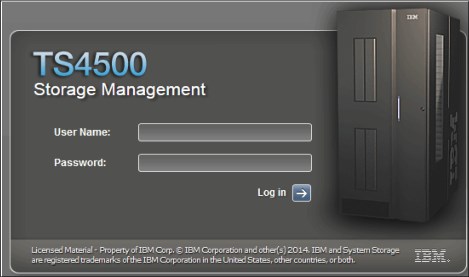
Figure 4-3 TS4500 login window
Setup wizard
If the TS4500 is a new installation, use the Initial Setup wizard, as shown in Figure 4-4. This wizard guides you through the basic configuration settings. The following settings are configured when you use the Initial Setup wizard. You can modify these settings from the Settings page of the management GUI.

Figure 4-4 Setup wizard
Complete the following steps:
1. In the window, as shown in Figure 4-5, you can enter the name of your library.

Figure 4-5 Setting the system name
2. In the next window, you can set the date and time for the library manually. Optionally, you can synchronize with a Network Time Protocol (NTP) server, as shown in Figure 4-6.

Figure 4-6 Date and time
3. Use the window that is shown in Figure 4-7 to configure a logical library, or you can skip this step and configure the logical library later.

Figure 4-7 Logical libraries
4. The window that is shown in Figure 4-8 displays a summary of all of the settings that were configured in the previous steps. Select Finish to complete the wizard and go to the main menu.

Figure 4-8 Summary
4.2.2 System summary display
After login the system summary window is shown, as in Figure 4-9.

Figure 4-9 System summary display
For more information about the Management Interface (MI) and the available functions, use the question mark (?) icon or Help, which is number 4 in Figure 4-9.
Table 4-3 lists all of the fields that are shown in the window. The numbers in Table 4-3 refer to the numbers that are shown in Figure 4-9 on page 193.
Table 4-3 System display
|
Number
|
Field
|
|
0
|
TS4500 tape library name.
|
|
1
|
Current menu tree position.
|
|
2
|
View of physical library that is installed.
|
|
3
|
Logged-in user name and role.
|
|
4
|
Help.
|
|
5
|
Library hardware actions menu.
|
|
6
|
Export Data menu.
|
|
7
|
Monitoring menu.
|
|
8
|
Library menu.
|
|
9
|
Drives menu.
|
|
10
|
Cartridges menu.
|
|
11
|
Access menu.
|
|
12
|
Settings menu.
|
|
13
|
Tasks icon. The Tasks icon displays when tasks are running.
|
|
141
|
The physical capacity pod displays the licensed capacity Linear Tape-Open (LTO) and (3592). This pod changes color to yellow or red, depending on whether the capacity exceeds the thresholds.
|
|
15
|
Switch the display to show the physical capacity per drive type by using the arrow on a mixed library.
|
|
16a
|
Drives in use status pod.
|
|
17a
|
All installed frames and status. This area is grouped into four frames. When this area is selected, the four frames show in the main window.
|
|
18a
|
Library health status pod. The color of the health status pod indicates the current state of the library by severity.
|
|
19
|
Frame health status pod for the selected frame. An icon is present in this field if an error or warning exists with a frame, tape drive, cartridge, or an accessor. Hover over the icon to see a list of the most important issues that cause this state. Click any issue to open the Events Page to see more information.
|
|
20
|
Library events icon. The library events icon displays if events are active.
|
1 Status PODs. Pods are always located at the bottom of the System page and show a quick view of capacity, drive utilization, and library health and changes color depending on the health or utilization settings.
4.3 Settings
Use the Settings menu as shown in Figure 4-10 to configure overall library options and settings. Each sub menu is described in the following sections.

Figure 4-10 Settings
4.3.1 Library
Select Library on the Settings menu to access the Library page to set the date and time, configure the advanced options, and work with licensed functions.
Date and Time option
Use the Date and Time option to set the library date and time. You can choose whether to set the date and time manually (see Figure 4-11) or to synchronize with the NTP server (see Figure 4-12 on page 196). If you select to use the NTP server, you can optionally insert a primary and secondary NTP server and test the connection from this display.

Figure 4-11 Set time manually

Figure 4-12 Synchronize with NTP Server
Advanced
Use the Advanced page to manage expired cleaning cartridges, and REST over SCSI as shown in Figure 4-13. If you have dual accessors the Advanced page will additionally show elastic capacity and active accessor options, as shown in Figure 4-14.

Figure 4-13 With single accessor

Figure 4-14 With dual accessors
Move expired cleaning cartridges to I/O station
The library uses the cleaning cartridge to automatically clean tape drives as needed to maintain the efficiency of the tape drives. This option allows the TS4500 to automatically move expired cleaning cartridges to the I/O station.
Each cleaning cartridge can be used 50 times. The usage count is stored internally in the cartridge memory chip inside each cleaning cartridge, which prevents an expired cleaning cartridge from being reused.
Elastic Capacity option
If the library has the High Availability (HA) feature (dual accessors), use this Elastic Capacity option to manage the way cartridges are stored in the accessor service areas. The following settings are available:
•Use for maximum capacity: The least recently used cartridges are moved to an accessor service area when the non-service area is 98% full.
•Use for temporary overflow: The I/O station cartridges are imported to an accessor service area when the non-service area is 100% full.
•Do not use: Cartridges are never moved to an accessor service area.
The accessor service area consists of the storage slots that only one accessor can manage. For more information, see “Elastic Capacity option” on page 21.
Active accessor
Use this Active Accessor option to enable and disable accessors, as required. If a service issue occurs with one accessor, you can select the accessor that works to service the whole library and disable the accessor that requires service. Figure 4-15 shows the display for setting either accessor A or accessor B as active and shows a representation of the available slots with a single accessor set.

Figure 4-15 Single active accessor
Accessor preferred zones
The Accessor preferred zones are read-only graphics, which display the preferred zone for each accessor, including the accessor service areas if Elastic Capacity is enabled.
Modifying the accessor zone configuration is done using the TS4500 setAccessorZones CLI command. This command can also be used to inactivate an accessor. This command is described in “viewAccessorZones” on page 369.
REST over SCSI
Use this option to enable (default) or disable REST over SCSI. REST over SCSI is described in detail in Chapter 6.
Licensed Functions
Licensed functions enable extended library capabilities that are available only to users who purchase and enter a license key code for that particular capability. All of the available extended capabilities are listed in the table on the Licensed Functions page. A green check mark in the Licensed column indicates that the license is installed.
You are required to enter the license key in the license key code field. The license key file is generated by manufacturing, and it is a unique number that is based on the serial number of the library. Select the frame number and enter the license key, as shown in Figure 4-16.

Figure 4-16 Licensed function
|
Note: Advanced Library Management System (ALMS), which comes standard on the TS4500, always shows as installed.
|
The following features are the extended library capabilities and they become available when the license key is uploaded:
•Path failover creates redundancy in the path from the application to the intended target (the library accessor or the drive mechanism).
•Intermediate high-density capacity on demand (HD CoD) increases storage from the entry capacity to the intermediate capacity. The Intermediate CoD feature (FC 1643) adds 100 slots, increasing the usable capacity of the L25 and L55 frames to 200 slots.
•Base capacity on demand (CoD) increases storage from the intermediate capacity to the base capacity. The Base CoD feature (FC 1644) adds 200 slots, increasing the usable capacity of the L25 and L55 frames to 400 slots.
•LTO transparent encryption is required to enable encryption on LTO tape drives if you use library-managed encryption (LME).
•High-density capacity on demand (HD CoD) increases storage to use all of the tiers of an HD frame. The initial capacity of the Dx5 frames is 500 slots. The initial capacity of the S25 frame is 600 slots. The initial capacity of the S55 frame is 660 slots. The HD CoD features can add 50 - 660 more slots anywhere, depending on the frame position and configuration. This license is required to be installed on each HD frame.
•It is possible to remove a licensed function by using right-click on a licensed function and selecting remove license key as shown in Figure 4-17.

Figure 4-17 Remove License Key
4.3.2 Networking
Select Networking on the Settings menu to access the Networking page to set up management Ethernet ports and iSCSI Ethernet ports on the TS1160 model 60E and TS1155 model 55E.
Management Ethernet Ports
Use the Management Ethernet Ports menu to display and configure the ports on each library controller card (LCC). Each port can enable or disable a particular protocol. The LCC that is specified for each port is the LCC to which that network connects when local hardware communicates with remote hardware.
By selecting the Network option, the Ethernet Ports window opens, as shown in Figure 4-18, which displays the current settings of all ports and displays their status.

Figure 4-18 Ethernet Ports window
Use this window to change the Internet Protocol (IP) address that you use to access the management GUI. Individual frames and ports can be configured to use IPv4, IPv6, or both types of IP addresses.
Use the Actions menu to modify an Ethernet port or display its properties, as shown in Figure 4-19.
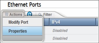
Figure 4-19 Ethernet ports
Modify port
To modify a port, highlight the port that you want to modify and select Actions → Modify Port. The Modify Frame window opens, as shown in Figure 4-20.

Figure 4-20 Modify Ethernet port settings
Use this window to change the IP address that you use to access the management GUI. You can configure individual frames, and ports can be configured to use IPv4, IPv6, or both types of IP addresses.
The following fields are available:
•The IPV4 assignment can be set to static, DHCP, or disabled:
– Static or fixed IP addresses are manually assigned to each system by an administrator.
– For Dynamic Host Configuration Protocol (DHCP), set this field to DHCP if you use a DHCP server, which automatically configures the IP address and network parameters.
•The IPV4 address, subnet, and gateway fields are used to set up a static IP configuration.
•The IPV4 primary and secondary Domain Name System (DNS) fields are used to set up the IP address of a DNS server, if required.
•The IPV6 assignment can be set to disabled, DHCP, stateless auto configure, or static:
– The static or fixed IP addresses are manually assigned to each system by an administrator.
– Set this field to DHCP if you use a DHCP server, which automatically configures the IP address and network parameters.
– Stateless auto configure allows a host to generate its own addresses. It uses a combination of the router prefix (identifies the subnet that is associated with a link) and a host-generated interface identifier (uniquely identifies an interface on a subnet).
•The IPV6 address, subnet, and gateway fields are used to set up a static IP configuration.
•The IPV6 primary and secondary DNS fields are used to set up the IP address of a DNS server, if required.
A link local address is an IP address that is intended only for communications within the segment of a local network. The link local address is not configurable. IPv6 is enabled per interface, and the IPv6 link local address is assigned to the interface where IPv6 is enabled.
Properties
This option displays the current configuration and link status of the selected port, as shown in Figure 4-21.

Figure 4-21 Ethernet port properties
iSCSI
This option provides for library-wide security setting for the TS1160 model 60E and the TS1155 model 55E iSCSI Ethernet ports.
Figure 4-22 shows the security setup options that are available for iSCSI.

Figure 4-22 iSCSI library wide security settings
The following are possible authentication settings for discovery and normal use:
•Disabled, which is the default
•CHAP enabled
•CHAP and NONE enabled
•NONE enabled
When Challenge-Handshake Authentication Protocol (CHAP) support is enabled, hosts are securely authenticated by the system. This increases overall system security by verifying that only authenticated parties are involved in host-storage interactions.
CHAP is an authentication process of an iSCSI initiator by a target through comparing a secret hash that the initiator submits with a computed hash of that initiator’s secret, which is stored on the target.
|
Note: Target authentication is disabled by default. Target user name and password are required if using CHAP and Target authentication is enabled.
|
4.3.3 Notifications
Select Notifications on the Settings menu to access the Notifications page to configure the sender information, recipient information, and library information for the various TS4500 tape library notifications. The Notifications page contains several options, as shown in Figure 4-23.

Figure 4-23 Notifications page
Library Information
The Library Information page displays the configured system name, system location, and company contact information for the TS4500 tape library. The library information is sent in Simple Network Management Protocol (SNMP), email, syslog, and Call Home notifications.
To modify all fields, complete the following steps:
2. The Modify option opens the window that is shown in Figure 4-24. On the Modify Library information window, you can set all of the system information and configure the library name (which can be changed concurrently).

Figure 4-24 Modify Library information window
3. Use this window to set the TS4500 system name, system location, and company contact details. The system name that is shown in the library information profile references the system name that is set during the initial configuration of the library. The system name appears in the navigation tree and notifications.
4. After you complete all of the settings, click OK to apply the changes.
SNMP Requests options
To set the SNMP Requests options, complete the following steps:
1. Select Notifications on the Settings page, as shown in Figure 4-10 on page 195, to configure how the TS4500 tape library sends SNMP traps and requests. SNMP notifications include SNMP traps and SNMP requests.
SNMP traps enable the tape library to send its profile to the SNMP server by way of an unsolicited SNMP message.
2. Under the Notifications menu, select SNMP Requests to display the current settings, as shown in Figure 4-25.

Figure 4-25 SNMP Requests
3. To change the setting, select Modify, as shown in Figure 4-25, which opens the Modify SNMP Settings window, as shown in Figure 4-26.

Figure 4-26 Modify SNMP Settings window
4. Select the SNMP state (Disabled or Enabled). When the SNMP state is Not allowed, the TS4500 tape library does not send messages to the network-attached devices for conditions that warrant administrative attention. When the SNMP status is Allowed, the library sends traps to automatically notify an administrator if an issue arises.
|
Note: Disabling SNMP does not delete any destinations that were set up.
|
SNMP is a networking protocol that, when it is enabled, allows the TS4500 tape library to automatically gather information about alerts and status. The system then transmits this information to other entities, such as an SNMP monitoring server, in the network. The gathered information is called an SNMP trap.
SNMP traps enable the TS4500 tape library to send its profile to the SNMP server by way of an unsolicited SNMP message. If an issue arises with the library, network, or any port in the network, the tape library responds with an information profile to the SNMP server. The nature of the profile depends on the type of issue that arose.
The SNMP community is the name of the class of users that can access the statistics of network-attached devices. The trap community name is sent with a trap. For information about the SNMP trap community name, see the documentation for your monitoring station. To view or change the community name that is associated with the TS4500 tape library, click Modify on the Modify SNMP Settings page (Figure 4-26 on page 205).
By default, the TS4500 tape library SNMP community is set to public. During the initial system configuration, the administrator can change the community name and customize the access settings for each community name.
SNMP Traps
Use the SNMP Traps window to configure SNMP destination servers, send test SNMP traps, and download the SNMP Management Information Base (MIB) file. You can also specify the type of messages (errors, warnings, or informational messages) that each SNMP destination server receives:
1. From the SNMP Destinations window, select the Create Destination tab to display the Add Destination window, as shown in Figure 4-27.

Figure 4-27 SNMP Traps window
2. Enter the destination SNMP server IP address and port number that are used, with the types of messages to send to the server.
3. Select Add to add the server and continue to create new servers if you require multiple servers with different roles.
You can select errors, warnings, and informational messages to send to the SNMP server.
4. From the SNMP Traps window, select Actions to modify or delete an existing destination server, send a test trap, or download the SNMP MIB file. Figure 4-28 shows these options.

Figure 4-28 SNMP Traps actions
The SNMP MIB file is used to interpret SNMP traps. When the GUI receives an SNMP trap, it compiles the SNMP trap into human-readable form so that you can gather information about the error.
The many components in a network are made by various manufacturers, and each component has unique properties and definitions. Data that is sent from the TS4500 tape library to any of the devices must be translated to a protocol that is understood by the device. An MIB file is a database that contains the properties and definitions of each network-attached device. The MIB file receives and translates the data when the TS4500 tape library sends the request for information.
SNMP query configuration
The TS4500 tape library stores its major configuration components in a standard Management Information Base (MIB) file. You can use an SNMP GetRequest to query the library and use the configuration MIB to translate the fields that gather configuration data for the TS4500 tape library and other IBM library types by using the SNMP query feature. The SNMP query feature is an easy way to gather configuration data from both local libraries and libraries that are in different geographic locations.
The following list shows all of the configuration data options that you can access for the frame or system configuration (frame or module):
•Logical Library
•Drive Configuration
•Library Configuration
•VPD Note Card
•Call Home Configuration
•SNMP
•Key Manager
•Drive Encryption
•SMTP configuration
•Time Configuration
•User Roles
•Role Access Level
•LDAP Configuration
•Ethernet Configuration
To download the configuration MIB file, select SNMP Traps, as shown in Figure 4-28 on page 206. Then, with the IP address highlighted, select Actions → Download SNMP MiB File.
Email Server
Email is a method, other than SNMP traps, to send information to users who need information about events that occur in the network. If your Simple Mail Transfer Protocol (SMTP) server requires authentication information before it accepts email notifications, you can set the authentication information, including the SMTP server port number, by using the Modify Email Settings page:
1. To access the Modify Email Settings page, click Modify on the Email Server page.

Figure 4-29 Email Server notifications page
3. After you complete all fields, click Test on the Modify Email Settings page. If the test is successful, click Modify to save the settings.
You can define a specific email destination or a specific Short Message Service (SMS) gateway to use certain SMTP gateways only.
SMTP dictates that every email message must specify the email address of the sender. This sender address must be a valid address for two reasons:
•Many SMTP gateways require a valid sender address as a security measure to prevent unauthorized usage of the SMTP server. Otherwise, the SMTP gateway does not forward the email. Often, this sender address must be limited to a specific domain.
•The sender’s address is used as the destination for error messages, such as an incorrect email address and a full email mailbox, that are generated by the SMTP gateways.
|
Note: The default SMTP server port value is set to 25, and can be changed to a secure port such as 465. Many email serves no longer permit port 25 so check with your email service provider or administrator for correct port to use.
|
Email Recipients
Use the Email Recipients page to add email addresses for recipients of the error notifications, warning notifications, and informational notifications:
1. Select Email Recipients.

Figure 4-30 Email Recipients option
3. You can add a number of recipients, based on their email addresses and local user names. Specify the email address to which you want to send the events, or you can optionally select a user if an email address was specified for that user when that user was defined.
4. You can also select the type of alert that a specific user can receive. Select Create to create an email recipient.
5. After a recipient is created, you can then modify the user, delete the user, or send a test email to the user from the Actions menu, as shown in Figure 4-31.

Figure 4-31 Email Recipients Actions menu
System log (Syslog) server
Use the Syslog Server option on the Notifications menu to set up a destination syslog server, as shown in Figure 4-32:
1. Click the Create Recipient tab.
2. Configure the IP address of the syslog server, the server port number and subscribe to the types of events to send to the syslog server. Click Create.

Figure 4-32 Syslog Server page
When system events occur, the TS4500 tape library creates a log of these events. You can configure the TS4500 tape library to send syslog notifications and send a notification of the event to the syslog server. The syslog server keeps its own log of system events. (The syslog server is a client-provided server.)
3. After the syslog server is set, you can use the Actions menu, as shown in Figure 4-33. You can modify, delete, or send a test to the IP address of a syslog server.

Figure 4-33 Syslog Server Notifications Actions menu
4.3.4 Security
Select Security on the Settings menu to access the Security page for the following functions:
•Enable and configure remote authentication
•Disable remote authentication
•Set access rules
•Enable or disable Secure Sockets Layer (SSL)
•Manage encryption
|
Note: The initial TS4500 implementation of remote authentication settings does not include a prompt for optional “service credentials”.
If service credentials are not supported or not entered, the library uses the user credentials to bind to and query the Lightweight Directory Access Protocol (LDAP)/Active Directory (AD) server.
If the TS4500 user does not have sufficient privileges to query the LDAP server, the TS4500 user authentication process fails. When service credentials (with the correct privileges) are supported and entered into the settings, this error does not occur.
|
Authentication
With authentication, security tasks are centralized and user management can be performed from a single interface, without logging in to the TS4500 tape library. (This capability was referred to as the Storage Authentication Service (SAS) with the TS3500 tape library.) The default status for remote authentication is Disabled, as shown in Figure 4-34.

Figure 4-34 Security Remote Authentication page
Disabled status
With disabled status for remote authentication, users are defined on the local library and the library uses local authentication to manage the access.
Enabled status
With remote authentication enabled, the users are defined on the remote library and authentication requests are passed to a remote authentication server (LDAP) that verifies the user’s name and password. For more information about user setup, see 4.4.1, “Users” on page 228.
To enable remote authentication, the following conditions are required:
•You must create a group and add users to that group on your remote authentication server.
•On the TS4500 tape library, create a custom role with a name that exactly matches the group name on the remote authentication server.
•Each custom role has unique access permissions.
•The primary LDAP repository Uniform Resource Identifier (URI) is required.
•The secondary LDAP repository URI is optional.
•The LDAP Transport Layer Security (TLS) certificate is optional.
•If you use Kerberos, you require the realm, key distribution center (KDC), domain mapping, and service keytab.
Lightweight Directory Access Protocol
LDAP is an open protocol that uses TCP/IP to provide access to directories that support an X.500 model. LDAP does not incur the resource requirements of the more complex X.500 Directory Access Protocol (DAP). For example, LDAP can be used to locate people, organizations, and other resources in an internet or intranet directory. The LDAP settings must conform to the following rules:
•The repository URI must start with ldap:// and end with a port number.
•The secondary repository URI must also start with ldap:// and end with a port number. If you do not have a secondary repository URI, leave this field blank.
The optional Transport Layer Security (TLS) certificate is purchased from a certifying entity. The TLS certificate is a plain text file that contains information about the web server. The TLS certificate verifies that it is indeed what it claims to be. (In this case, the web server is the TS4500 tape library.) The TLS certificate that is stored on the TS4500 tape library enables your web browser to access the TS4500 tape library without challenging its validity. The credential is the LDAP equivalent to a password.
Kerberos
Kerberos is a network authentication protocol that is based on symmetric key cryptography. Kerberos assigns a unique key, which is called a ticket, to each user who logs on to the network. The ticket is embedded in messages that are sent over the network. The receiver of a message uses the ticket to authenticate the sender.
Kerberos settings include the following characteristics:
•The Kerberos realm is generally the same as your company’s domain name. For example, if your company’s domain name is example.com, your Kerberos realm is EXAMPLE.COM.
•The Key Distribution Center (KDC) (AD server) is the Key Distribution Center server. A KDC server generally has a prefix of “Kerberos” followed by your Kerberos realm, a colon, and the port number of the Kerberos server. (The port number of the Kerberos server is 88 for the TS4500 tape library.) So, if your company’s domain name is example.com, a conventional name for your KDC server is kerberos.example.com:88.
•The Domain mapping field is optional.
The Service keytab must be stored on the TS4500 tape library. It is used as part of the authentication process to verify which user is connecting to it. A Service keytab that is stored on the TS4500 tape library enables automated authentication.
Custom roles
With remote authentication, custom roles are defined on the remote authentication server:
•You must create a group and add users to that group on the remote authentication server.
•On the TS4500 tape library, create a custom role with a name that exactly matches the group name on the remote authentication server.
Each custom role has unique access permissions. For more information about custom roles, see 4.4.2, “Roles” on page 234.
Enable remote authentication
After you complete all required preparation and configuration, select Actions to enable remote authentication, as shown in Figure 4-34 on page 211. The Remote authentication window opens. The first page lists the prerequisite actions before you can enable remote authentication, as shown in Figure 4-35.

Figure 4-35 Remote authentication Preparation window
The next three steps require you to select the user group that was created for remote access on the Create Group window, and to confirm that this user group is the same user that is assigned to the server on the Assign a User window, then select the authentication method to use (see Figure 4-36).

Figure 4-36 Remote authentication preparation
Kerberos
If you selected the Kerberos authentication method, the Kerberos Settings window opens (see Figure 4-37).

Figure 4-37 Kerberos setting
Complete these steps in the Kerberos Settings window:
1. Enter the name of the realm setup for this machine.
2. Enter the KDC (AD) server name.
3. Enter the Domain mapping.
Figure 4-38 shows an example of the settings used for kerberos setup. After the settings are chosen, click Next to perform a connection check with the KDC (AD server). A green check mark appears if a connection is made. If a connection cannot be made to the server, a red cross appears.

Figure 4-38 Kerberos example settings
LDAP
If LDAP is selected, the LDAP Settings window opens, as shown in Figure 4-39. Complete the required fields in this frame.

Figure 4-39 LDAP Settings
Configure the following settings on the TS4500 tape library:
•LDAP Repository URl: This field starts with ldap:// and ends with a port number.
•Secondary LDAP Repository URI: This field starts with ldap:// and ends with a port number. If you do not have a Secondary Repository URI, leave this field blank.
•LDAP StartTLS: Enabling the LDAP StartTLS starts a normal LDAP session and initiates the TLS (Transport Layer Security) layer. This is an optional selection.
•LDAP TLS certificate: The LDAP TLS certificate is purchased from a certifying entity. It is a plain text file that contains information about the web server, and verifies that it is what it claims to be.
The TLS certificate that is stored in the TS4500 tape library enables the web browser to access the TS4500 tape library, without challenging its validity. This is required if LDAP StartTLS is enabled. If a TSL certificate is not available, disable LDAP StartTLS.
•Service Credentials: The service credentials include the username and password for the LDAP administrator account. The service credentials are necessary if the LDAP server does not support anonymous access. Anonymous access means that any entity can access and view records without being authenticated by the LDAP server.
The username field must follow LDAP distinguished names (DNs) format to lookup correct service credential user. In Figure 4-40, the user credentials are CN=Tom,CN=Users,DC=ldapserver1,DC=example,DC=com. In the example, the CN attribute is used to search for users within the LDAP server, and the DC attribute is used to point to a LDAP server. The output is a generic example. Therefore, replace the appropriate fields and attributes according to your LDAP settings.
|
Note: The LDAP settings are tested when you select Next. If the settings are correct and communication works, a green check mark appears next to the LDAP repository URI. Then, continue with the next setting. If the LDAP URl is not setup or no connection exists, or if a setup cannot be done, a red cross (+) appears next to the URl.
|

Figure 4-40 LDAP example settings
Two LDAP lookup methods are available: Simple lookup and Advanced lookup. Simple lookup is the default lookup method and uses group and user LDAP distinguished names (DNs) for authentication lookup. After you enter the settings, click Next to continue to the options for the lookup method.
Figure 4-41 shows an example of a completed Simple lookup method page that includes an example of the format of the required fields.

Figure 4-41 Simple lookup method example
The Advanced search option provides more flexible searching and better performance. The Advanced search lookup method has the following search fields, required to be complete:
Base DN: Allows you to customize the Base Distinguished name to begin the LDAP search, which begins the search deeper in the LDAP tree for better performance.
Group name Allows you to choose what attribute in the LDAP group accounts is used to associate with a TS4500 role.
User name Allows you to customize which attribute in the LDAP user account is used for user names.
Group Member Allows you to customize the link between the LDAP users and groups.
The following fields are optional when selecting Advanced search and are used to improve LDAP search performance:
•User name filter
•Group name filter
Select the advanced search lookup method by selecting the Advanced search option, as shown in Figure 4-42, which also shows how to complete the Advanced search within the LDAP lookup method.

Figure 4-42 Advanced search example
After entering the settings, click Next to continue to test the settings are correct and to confirm access to the servers. In the Confirm Access page, for the Remote UID field, add a user that was created inside the LDAP server. If all settings are correct, remote authentication is enabled and logs all users out of the management GUI.
Disabling remote authentication
After successfully enabling remote authentication, clicking Security → Remote Authentication → Actions prompts a Disable remote authentication option. Selecting this option prompts the user to confirm remote authentication disablement. Upon confirmation, log all LDAP users out of the management GUI and revert to local authentication.
Password and Session Policy
Figure 4-43 shows the Password and Session Policy window, which displays the current settings.

Figure 4-43 Password and Session Policy page
If the default password and session policy settings are not strict enough for your company’s rules, you can customize the settings on the Password and Session Policy window by selecting Modify.
You can modify all of the settings that relate to the session and password policy, as shown in Figure 4-44. These settings can be set back to the default settings by selecting Reset to Default in this window.

Figure 4-44 Modify Password and Session Policy window
A preset local user that is called localGUI, with the role of monitor, is enabled by default with the TS4500 tape library. This default allows a local user to access the integrated management console (IMC) without logging in.
However, if your company policies and procedures prohibit this type of quick access to the System Summary view, you can disable this local user login function. To disable the user login function, select Settings → Security → Password and Session Policy, and set the Automatic IMC (local GUI) login at power on setting so that a password is required.
Secure communications
Use this option to manage encryption settings for the GUI and command-line interface (CLI) communications with the library.
The TS4500 tape library is secured with a Secure Sockets Layer (SSL). SSL is a protocol for encrypted (secure) transmission through the internet.
Use the Secure Communications page to configure the SSL settings (see Figure 4-45).

Figure 4-45 HTTPS
Use the Secure Communications window to enable or disable SSL or to update a certificate. Selecting Enable or Update provides the option to upload an SSL web certificate. This window also displays the type of certificate that is used and the upload date and expiration date.
SSL is a cryptographic security system that uses the following keys to encrypt data:
•A public key that is known to everyone
•A private key that is known only to the recipient of the message
Many websites use this protocol to obtain confidential user information, such as credit card numbers. By convention, URLs that require an SSL connection start with https instead of http. HTTPS stands for Hypertext Transfer Protocol Secure.
Secure communications on
When the secure communications function is on, the data that is exchanged between the TS4500 tape library and the browser or CLI is encrypted. In the browser, you must add and confirm security exception to login. For CLI, you must use the --ssl option to run CLI commands.
Secure communications off
When the secure communications function is off, your browser or CLI and the TS4500 tape library communicate with unencrypted data transmissions. Your browser uses a TLS certificate to verify the validity of the TS4500 tape library.
Update web certificate
SSL web certificates are small data files that digitally bind a cryptographic key to an organization’s details. When an SSL web certificate is installed on a web server, it activates the padlock and the https protocol (over port 443) and allows secure connections from a web server to a browser. This option can be used to update a certificate or replace an expired certificate.
The following options are available when you enable secure communications or update a certificate:
•System-defined
The SSL cipher specification list system value is read-only. Its values are automatically modified to contain the list of cipher suites that are supported by the system SSL. If you use this option, the SSL cipher specification list system value is automatically updated with new cipher suite capabilities when you install or upgrade to a future release of the firmware system.
•User-defined
If a certificate exists, its identifying information is displayed in the Certificate field. You can use this certificate, or click the folder icon to upload another certificate.
|
Note: If you modify a certificate that was uploaded, you must re-select the PEM file by clicking the folder icon and specifying the file, even if the name is still displayed in the Certificate field. If the certificate is encrypted, you must re-enter the password.
|
Consider the following points regarding certificates:
•RSA keys are recommended. No specific key size is required.
•Certificates must use AES encryption. DES is not supported.
•Certificates must be in PEM format. They can be self-signed or CA-signed, but must contain the certificate and the private key. If the private key is encrypted, you must enter the password for the private key.
•Certificates with the SHA256 signature algorithm are supported. Certificates with SHA1 or MD5 hash signatures are not allowed.
•Both wildcard and multi-domain (SAN) certificates are supported. A wildcard certificate allows unlimited subdomains to be protected with a single certificate. A SAN certificate allows for multiple domain names to be protected with a single certificate.
If you are using CA-signed certificates on a TS4500 tape library configured with multiple IPs, it is strongly recommended to include each IP used for web GUI access in the certificate. If an IP address or DNS name is not specified in the certificate, the message, “Your connection is not secure”, is displayed after the web server restarts. Click Add Exception → Confirm Security Exception to use that certificate.
For more information about SSL, see IBM Knowledge Center:
Encryption key servers
Use the Encryption Key Servers page to manage the key servers that use an encryption key.
From the Add Server tab, add each encryption key server to use on the logical libraries configuration of this TS4500, as shown in Figure 4-46. This action makes the IP address of the server available when you set up library-managed encryption on the logical library.

Figure 4-46 Encryption Key Servers page
Encryption is managed at the logical library level. All encryption-enabled drives that are assigned to a logical library use the same method of encryption. For more information about methods of encryption, see 4.7.2, “Create Logical Library window” on page 284 and Chapter 3, “Encryption” on page 177.
The Add Encryption Key Server window requires you to first check with an Internet Control Message Protocol (ICMP) ping to ensure that the server is available when you add the server. Click Ping (see Figure 4-46) when you add a server to the list. Encryption key servers can also be added when you modify a logical library.
|
Note: The TS4500 supports the configuration of four encryption key servers for each logical library.
|
Run Diagnostics
If you want to verify the functionality of all of the network-attached devices, you can run diagnostics on the devices. Select Actions → Run Diagnostics. Then, select the drive or select drive to test and select Run Diagnostics.
The diagnostics process runs for a few minutes. When the diagnostics complete, the window shows a check mark for devices that passed the test, as shown in Figure 4-47, or a red error icon for devices that failed the test.

Figure 4-47 Encryption Key Servers diagnostics
|
Note: When you use the Run Diagnostics function, a warning icon might appear in the Ethernet column if you disabled Internet Control Message Protocol (ICMP) requests.
At least one key server IP address must be selected for the Run Diagnostics option to display on the Actions menu (or the right-click drop-down menu). If no key server
IP address is added (or selected), the Run Diagnostics option does not display on the Actions menu. This server must be configured on a logical library for diagnostics to run. |
ICMP requests
Internet Control Message Protocol (ICMP) is a messaging protocol (external to the TS4500 tape library) that sends error messages that a requested service is not available or that one of the network-attached devices cannot be reached. ICMP requests are disabled or enabled on the server on which the IBM Security Key Lifecycle Manager runs.
The disabled status of ICMP requests can trigger a warning in the Ethernet column when the Run Diagnostics function starts.
If ICMP requests are disabled, the server that the Encryption Key Manager runs on does not return a ping when the diagnostics are run, which triggers a warning in the Ethernet column of the Run Diagnostics table. If a warning appears in the Ethernet column, but no warning appears in the Key Server Path column, ignore the warning in the Ethernet column. If warnings appear in the Ethernet column and the Key Server Path column, the failure might be on the machine, or the network connections between the library and that machine.
Encryption Internal Label
Use the Encryption Internal Label page to create, change, or delete mappings from the cartridge key labels to the key-encrypting labels.
When the Encryption Internal Label option is configured, the encryption-enabled tape drive automatically derives the encryption policy and key information from the metadata that is written on the tape volume by the TS4500 tape library. Mapping the cartridge key labels to the key-encrypting labels enables the TS4500 tape library to apply the same encryption policy for both types of labels. The Encryption Internal Label is a way for the system to share encryption policies.
For a TS4500 with only a single drive type that is installed, either Linear Tape-Open (LTO) or 3592, only one option is shown on the Security page, as shown in Figure 4-48.

Figure 4-48 Single drive type Encryption Internal Label
Encryption is managed at the logical library level. All encryption-enabled drives that are assigned to a logical library use the same method of encryption. For more information about methods of encryption, see 4.7.2, “Create Logical Library window” on page 284 and Chapter 3, “Encryption” on page 177.
The examples that are shown in the next sections show the display for a mixed drive type library.
Encryption Internal Label 3592
To configure key label mapping, select Encryption Internal Label 3592 and then, select the Create Mapping tab, as shown in Figure 4-49. Select the method to use and then, select the key labels, as required.

Figure 4-49 Add or modify key label mapping for 3592
The following values are available for the “Map to key mode” field:
•Wrapped-Default: The map to key encryption method is configured by using the Encryption Key Manager default. (This option is for 3592 cartridges only.)
•Wrapped-Clear: The externally encoded data key (EEDK) is referenced by the specified key label. (This option is for 3592 cartridges only.) The Wrapped-Clear method is typically specified when encrypted volumes are kept in-house where each keystore references the keys by using the same key labels.
•Wrapped-Hash: The EEDK is referenced by a computer value that corresponds to the public key that is referenced by the specified key label. (This option is for 3592 cartridges only.) The Wrapped-Hash method facilitates exchange with a business partner or when volumes are sent to a disaster recovery site where the key labels might differ for the same key.
Encryption Internal Label LTO
To configure key label mapping, select Encryption Internal Label LTO and then, select the Create Mapping tab, as shown in Figure 4-50. Select the method to use and the key labels, as required.

Figure 4-50 Add or modify key label mapping for LTO
The following values are available for the “Map to key mode” field:
•Direct-Default Set: The map to label is determined from the encryption key manager. The label was configured at the encryption key manager, and the key label field is left blank. (This option is for LTO cartridges only.)
•Direct-Specific: The specified key label references a symmetric data key. (This option is for LTO cartridges only.)
4.3.5 GUI Preferences
Select GUI Preferences on the Settings menu to access the GUI Preferences page to control the behavior of the navigation dock. Use the Navigation page in the TS4500 Library to enable or disable the animation of the navigation dock in the GUI. Figure 4-51 shows example of animation enabled.

Figure 4-51 Enabled navigation animation
You can turn off the animation if the enlarged icons obscure any information in the window. Also, turning off the navigation animation helps increase performance when you are remotely connecting to the TS4500 over a slow network connection. Figure 4-52 shows example of animation disabled.

Figure 4-52 Disabled navigation animation
4.4 Access menu
Use the TS4500 management GUI pages (which is under the Access icon), as shown in Figure 4-53, to view, create, and assign users and their roles.

Figure 4-53 Access menu
|
Note: The options and actions under the Access icon are available only to users with the administrator role.
|
4.4.1 Users
Administrators can create and manage users, map users to a role, and view which users have active sessions and how many connections they have from the Users page.
|
Note: With the TS4500 tape library, password protection is always enabled and all users are required to sign in with a user name and password.
|
Selecting Users from the Access menu gives an overview of all configured users, as shown in Figure 4-54.

Figure 4-54 Create User tab
Table 4-4 lists the fields that are available on the Create User tab. The numbers in the table correspond to the numbers that are shown in Figure 4-54 on page 228.
Table 4-4 User window
|
Number
|
Description
|
|
1
|
Create User tab to add a user
|
|
2
|
Name of user
|
|
3
|
Actions tab
|
|
4
|
Filter user or search tab
|
|
5
|
Save user list to file
|
|
6
|
Locked state of user
|
|
7
|
Connected state of user
|
|
8
|
User role
|
|
9
|
View menu options
|
The actions that are available from the Users page differ, depending on whether the library is configured for local or remote authentication. Table 4-5 lists the available actions.
Table 4-5 Local and remote authentication actions
|
Actions
|
Local authentication
|
Remote authentication
|
|
Create User
|
X
|
|
|
Map To Role
|
X
|
|
|
Modify Email
|
X
|
|
|
Reset Password
|
X
|
|
|
Delete User
|
X
|
|
|
Disconnect
|
X
|
X
|
|
Connections
|
X
|
X
|
|
Properties
|
X
|
X
|
Local authentication
With local authentication, each TS4500 tape library maintains a separate database of user names with corresponding passwords and roles. Therefore, user management must be performed on each library.
When local authentication is enabled, the Users page shows all users and their state (connected or disconnected). The number of active connections is displayed next to the user state. It is also possible to view and modify email addresses when local authentication is enabled.
Remote authentication
With remote authentication, security tasks are centralized and user management can be performed from a single interface, without logging in to the TS4500 tape library. This function was referred to as the Storage Authentication Service (SAS) with the TS3500 tape library.
When remote authentication is enabled, authentication requests are passed to a remote authentication server (LDAP) that verifies the user’s name and password. When the user is created on the remote authentication server, the administrator assigns that user to an LDAP group. The group is then matched to a custom role on the TS4500 tape library, which specifies the access permissions for that logged-in user.
|
Important: The name of the group on the remote authentication server must be the same as the name of the role on the TS4500 tape library for the group to be matched to that role.
|
The “create” action is disabled on the Users page when remote authentication is enabled because you must create the user on the remote authentication server first. In addition, modifying a user’s email, password, and user group must be performed on the remote authentication server. Only connected users are shown on the User page, as shown in Figure 4-54 on page 228.
For more information about enabling remote authentication, see “Enable remote authentication” on page 213.
IMC access by a local user
In some environments, it is possible to rely on the physical security of the data center as the default operating mode. For this scenario, the TS4500 tape library allows a local user to access the Integrated Management Console (IMC) without logging in, enabling quick access to the System Summary view of the TS4500 management GUI.
A preset local user called localGUI, with the role of monitor, is enabled by default with the TS4500 tape library. This is the only local user that is valid when remote authentication is enabled.
If the localGUI user is deleted, all users are required to log in at the IMC.
To disable this local user login function and show the login window at the IMC, click Settings → Security and then, select Access Rules.
Creating users
You can create up to 80 users, each with a unique user name and password.
Each user account is mapped to a role that defines the pages that the user can view and the actions that the user can perform. Each user can be mapped to only one role, but multiple users can be mapped to any role.
For more information about the user roles and how to configure them, see 4.4.2, “Roles” on page 234.
To create a user, select Create User in the Users window. The Create User window opens, as shown in Figure 4-55. Enter the user name and role. The user receives the role that is chosen from the Role drop-down list. If you do not want the user to receive a default role, ensure that the role is first set up so that it can appear on the drop-down list.

Figure 4-55 Create User option
For more information about creating and managing roles, see 4.4.2, “Roles” on page 234.
A user can receive the temporary password through one of the following methods:
•If the Send password to this email option is selected, you must specify a valid email address for a user so that the user can receive passwords and email notifications. You must set up email notifications first (for more information, see “Email Server” on page 207).
When a user is created or when a user’s password is reset, the temporary password is automatically sent to the email address of the user, rather than to an administrator. A user with a valid email address can also be selected as a recipient of email alerts from the Notifications page.
•If an email address is not specified, an administrator is responsible for generating a new password or resetting a password and informing the user.
The password that you set must conform to the rules that are defined on the Password and Session Policy window. For more information, see “Password and Session Policy” on page 219.
|
Important: Because a user’s password expires after the user is created, a new user is prompted to reset the password the first time that the new user logs in.
|
After all fields are completed, select Modify to receive a message that confirms that the user is created and a reminder that the password is only temporary (see Figure 4-56).

Figure 4-56 User Created message
|
Note: It is highly advised to create at least two separate Administrator users because only the Administrator can reset or unlock a user password.
|
First-time login
When a user logs in for the first time, the user is presented with the login window. The user must enter their username and temporary password to start the login process, as shown in Figure 4-57.

Figure 4-57 User login
The user is then presented with the change password window, as shown in Figure 4-58.

Figure 4-58 Change password
The new password must conform to rules defined in the Password and Session Policy. For more information, see “Password and Session Policy” on page 219.
|
Note: The username and password are case-sensitive.
|
After the user sets their password, the user logs in with the new password in the initial login window, as shown in Figure 4-57. After the user logs in with the new password, the user can access the TS4500 management GUI with access to the assigned role.
Modifying a user
An administrator can perform several actions on a user by selecting the user and using the Actions menu, as shown in Figure 4-59.

Figure 4-59 Actions
The following functions are available on the Actions menu:
•Map to Role: The administrator can map a new role to a user. If the user is logged in, this action logs out the user.
•Modify Email: The administrator can modify or add an email address to a user.
•Reset Password: The administrator can reset a user password and provide the user with a temporary password. The user must change this password to a new password by using the same procedure that is described in “First-time login” on page 232.
•Unlock: If a user is locked out because the user exceeded the maximum number of unsuccessful login attempts, an administrator can unlock the user. The locked user shows a locked icon on the user list, as shown in Figure 4-60.

Figure 4-60 Locked user
If the user lost their password, any administrator can reset the password. If the user is locked, the administrator must unlock the user first.
•Delete: An administrator can delete a user. The user must be in a disconnected state to be deleted.
•Disconnect: An administrator can disconnect a user from the TS4500.
•Connections: This option lists the IP addresses that were used by the selected user to log in to the system. This option shows whether a user is being used multiple times and from what address.
•Properties: This option displays the properties of the user, the state of the user, and the user’s last connection, as shown in Figure 4-61.

Figure 4-61 User properties
Locked out
If you are locked out of the TS4500 management GUI, you can revert to the default administrator user name and password by using the reset button located on the panel near the pause button of the TS4500 tape library. This button resets the user name and password to the default logon settings for 15 minutes.
Use this reset button only for emergencies, for example, if the remote authentication server is down or if the administrator loses or forgets their password and no administrators can access the system. For more information about this process, see “Access Recovery” on page 52.
4.4.2 Roles
Roles define the pages that users can view and the actions that they can perform. Library administrators manage roles and the users that are assigned to them. Figure 4-62 shows the Role window.

Figure 4-62 Role window
Preset roles
The TS4500 tape library has four preset roles, each with a different level of access to the TS4500 management GUI. It is also possible to create up to 16 roles, each with a custom name and one of the preset permission levels. All roles have access to all logical libraries.
You cannot rename, delete, or modify the access permissions for any of the preset roles.
The following roles are preset default roles:
•Monitor: Users that are mapped to this role can view all physical and library data, but they cannot view user accounts or security settings. This role is useful for library operators.
•Superuser: Users that are mapped to this role can view all pages and perform library tasks, but they cannot manage users, modify security settings, or access service-related functions.
•Administrator: Users that are mapped to this role can perform all library tasks, including managing access and security, but they cannot access service-related functions.
•Service: Users that are mapped to this role can view all pages that are available to a monitor role. Additionally, this role can perform service-related functions, such as updating firmware, downloading logs, calibrating library components, and performing diagnostic tests. This role is useful for IBM service support representatives (SSRs).
When this user logs in to the TS4500 management GUI, certain tables display additional information, and several of the available actions differ from the actions that are available for the other roles.
Custom roles
Users that are mapped to a role with a customized name can view all of the pages that are available to the selected preset permission level of the custom role.
|
Note: The permissions of a custom role with service-level access cannot be modified, even from the TS4500 CLI.
|
Creating or deleting a role
Complete the following steps to name new roles and assign their permission by selecting from the preset role permission levels:
1. Create roles by selecting Access → Roles.
2. Select the Create Role tab.
3. Enter a name for the role.
4. Select one of the preset role permission levels from the Duplicate permission from list box (see Figure 4-63 on page 236). All roles can access all logical libraries in the TS4500 tape library.

Figure 4-63 Creating a role
To remove a role, select the role. Then, click Access → Roles → Actions → Delete. You can delete a role only if no users are assigned to the role.
You can also use the TS4500 CLI to create, modify, and delete roles, and to customize the permissions of a role.
|
Note: You must create a custom role before a user can be assigned to it.
|
Modifying the permissions of a role
You can modify customized role tasks from the TS4500 CLI only. However, the role must be created first by using the process that is described in “Creating or deleting a role” on page 235.
Ensure that the TS4500 CLI is installed. Open a command prompt in the same directory as the .jar file.
The CLI command features the following format:
java -jar TS4500_CLI.jar "C:[pathname_of_ts4500_cli.jar]" -ip [LCC ip] -u [username] -p [password] --[cli_command]
This command is useful to gather current role permissions that you can modify.
|
Note: If SSL is enabled on the TS4500 tape library, you must add the --ssl parameter to the command after the password, as shown in the following example:
java -jar TS4500CLI.jar -ip [LCC ip] -u [username] -p [password] --ssl --[CLI_command]
|
viewRolePermissions
The viewRolePermissions command displays a list of all permissions for a specified role. For example, we set up a role that is called Redbooks, which we want to save to a file that is called role.txt, as shown in Example 4-1.
Example 4-1 viewRolePermissions command
C:TS4500>java -jar TS4500CLI.jar -ip 10.1.121.99 -u Redbooks -p RedB00ks --view
RolePermissions Redbooks > role.txt
Action, Access Level
AIT, No Access
Cartridges, Modify
Cartridges by Logical Library, Modify
Cleaning Cartridges, Modify
Debug Messages, No Access
Drives, Modify
Drives by Logical Library, Modify
Email Notifications, Modify
Email Recipients, Modify
Encryption Internal, Modify
Encryption Key Manager, Modify
Ethernet Ports, Modify
Events, Modify
Library Information, Modify
Licensed Functions, Modify
Logical Libraries, Modify
Management GUI Behavior, Modify
Master Console, No Access
Password Rules, Modify
Position Control, No Access
Remote Authentication, Modify
Roles, Modify
SNMP Destinations, Modify
SNMP Notifications, Modify
Scan Speed, No Access
Secure Socket Layer, Modify
Service Port, No Access
Syslogs Notifications, Modify
System, Modify
System Date and Time, Modify
Tasks, Modify
Users, Modify
VOLSER Ranges, Modify
VOLSER Ranges by Logical Library, Modify
The output of this command is saved to our file, role.txt. You can now modify this file and change roles to suit your requirements. The output from this command can also be copied to another text file and modified.
setRolePermissions
The setRolePermissions command sets up custom roles to the permissions for a specified role. First, edit the text file that was created by using the viewRolePermissions command. Then, set the new permissions by using the setRolePermissions command, as shown in Example 4-2.
Example 4-2 setRolePermissions
C:TS4500>java -jar TS4500CLI.jar -ip 10.1.121.99 -u Redbooks -p RedB00ks --set
RolePermissions rolenew.txt -role Redbooks
The permissions were updated successfully
To confirm that the role is changed, run the viewRolePermissions command, as shown in Example 4-3.
Example 4-3 Confirming that role is changed
C:TS4500>java -jar TS4500CLI.jar -ip 10.1.121.99 -u Redbooks -p RedB00ks --view
RolePermissions Redbooks > rolenew.txt
Action, Access Level
AIT, No Access
Cartridges, Modify
Cartridges by Logical Library, Modify
Cleaning Cartridges, Modify
Debug Messages, No Access
Drives, Modify
Drives by Logical Library, Modify
Email Notifications, Read Only
Email Recipients, Read Only
Encryption Internal, Read Only
Encryption Key Manager, Modify
Ethernet Ports, Modify
Events, Modify
Library Information, Modify
Licensed Functions, Modify
Logical Libraries, Modify
Management GUI Behavior, Modify
Master Console, No Access
Password Rules, Modify
Position Control, No Access
Remote Authentication, Modify
Roles, Modify
SNMP Destinations, Modify
SNMP Notifications, Modify
Scan Speed, No Access
Secure Socket Layer, Modify
Service Port, No Access
Syslogs Notifications, Modify
System, Modify
System Date and Time, Modify
Tasks, Modify
Users, Modify
VOLSER Ranges, Modify
VOLSER Ranges by Logical Library, Modify
For more information about the TS4500, see Chapter 5, “Command-line interface” on page 323.
4.5 Cartridges menu
Use the TS4500 management GUI pages that are available under the Cartridges icon to view all cartridges, view cartridges by logical library, assign and move cartridges, and modify logical libraries, as shown in Figure 4-64.

Figure 4-64 Cartridges menu
4.5.1 Cartridges
Use the Cartridges page to move cartridges to a different location, remove cartridges to an I/O station, assign cartridges to a logical library, or unassign cartridges from a logical library.
The Cartridges menu has the following functions:
•Searching for cartridges
•Viewing cleaning cartridge status
•Viewing cartridge states
•Assigning or unassigning cartridges
•Fixing a tape with an unknown volume serial number (VOLSER)
•Selecting priority for media verification
•Moving cartridges
•Exporting the mount history
•Performing other cartridge tasks from the CLI
Figure 4-65 shows the main Cartridges window.

Figure 4-65 Cartridges
Searching for cartridges
You can use the Cartridges table to find specific cartridges and view their state (slot, I/O slot, drive, or gripper). Sort the table to locate specific tape cartridges. You can sort by VOLSER, state, location, logical library, element address, or most recent use. Go to the Cartridges by Logical Library page to see the cartridges, which are displayed by their logical library.
Search for specific cartridges by using the filter. Click Filter and enter a value in the search field or click the Advanced Filter icon to the right of the search field to enter extended search criteria, as shown in Figure 4-66. Enter substrings if the entire value is unknown. Wildcard characters are not supported. Instead of wildcard characters, you can add substrings to the search by clicking the plus sign (+) at the end of each criterion. (Search values are not case-sensitive.)

Figure 4-66 Advanced Filter option
The Cartridge database can be saved to a .csv file from the save option. It is also possible to save the list of cartridges that results from a search. To export the cartridge data, select the Export Data or Save icon (diskette), and then, select Export Table Data, as shown in Figure 4-67.

Figure 4-67 Save list
Viewing cleaning cartridge status
IBM supplies a cleaning cartridge with the first frame of each media type in a library. The library uses the cleaning cartridge to automatically clean tape drives, as needed, to maintain the efficiency of the tape drives. Each cleaning cartridge can be used up to 50 times.
This option is used to view how many cleanings remain on a cleaning cartridge. The number of remaining cleanings is displayed in the Cleans Remaining column of the Cartridges table. This column is hidden, by default.
Right-click the table header to select the Cleans Remaining column. To see all cleaning media in the TS4500, sort the column by Cleans Remaining by using the arrow, as shown in Figure 4-68.

Figure 4-68 Remaining cleanings
You can also view how many cleaning cycles remain on all cleaning cartridges in a logical library on the Cartridges by Logical Library page.
You can optionally eject expired cleaning cartridges automatically. For more information about enabling this feature, see “Advanced” on page 196.
|
Note: Cleaning cartridges are shared among logical libraries.
|
Cartridge state
The State column in the Cartridges table lists the current state for each cartridge. The following states are possible:
•Drive: A tape cartridge is in a tape drive.
•Gripper: A tape cartridge is in the gripper of the cartridge accessor.
•I/O Slot (Import Queued): A tape cartridge is in an I/O slot, but it is queued to move to a storage slot.
•I/O Slot: A tape cartridge was moved to the I/O station. This state is cleared if the cartridge is moved by the operator to any other location, including a different I/O station slot.
•Slot: A tape cartridge is in a storage slot.
•Slot (Assignment Pending): A tape cartridge is in the Unassigned logical library because an empty import/export element (IEE) address is not currently available for assignment.
•Slot (Export Queued): A tape cartridge was queued to move from a slot to the I/O station by one of the following methods:
– The host issues a move command from the storage element to the IEE.
– An operator selects a Move To I/O Slot operation from the management GUI.
•Slot (Virtual I/O): A tape cartridge was imported (physically moved) into the slot, but it is still in the virtual I/O (VIO) element address space and it is not queued for export.
Assigning or unassigning cartridges
A bar code label with a volume serial (VOLSER) number is affixed to each cartridge. Cartridges are assigned to a logical library with VOLSER ranges that are defined when the logical library is created. If the VOLSER range that is assigned to a logical library matches the VOLSER of a cartridge, that cartridge is assigned to the logical library. If the VOLSER of a newly inserted cartridge does not match the VOLSER range of a logical library, the cartridge is available to import into any logical library of the same media type.
The assignment is then determined by the first application to import the cartridge. VOLSER ranges were called the Cartridge Assignment Policy with the TS3500 tape library.
You can modify the cartridges that are assigned to a logical library by modifying the VOLSER range of the logical library from the VOLSER Ranges by Logical Library page.
Assigning a cartridge
If an individual cartridge is outside of a VOLSER range, you can use the Assign action to assign that cartridge to a specific logical library. However, creating VOLSER ranges is the preferred method for assigning cartridges to logical libraries.
To assign or reassign cartridges to a logical library, highlight one or more cartridges from the same logical library and then, select Actions → Assign, as shown in Figure 4-69.

Figure 4-69 Assign selection
You can bulk assign all available or unassigned cartridges from the Cartridges by Logical Library page by highlighting the Available or Unassigned cartridge rows and selecting Actions → Assign All Cartridges.
|
Note: If the new cartridge assignments exceed the maximum number of cartridges that is allowed by a logical library, any other cartridges are unassigned. Go to the Logical Libraries page to modify the maximum number of cartridges that is allowed, and then attempt to assign the cartridge again.
|
Unassigning cartridges
To unassign one or more cartridges, select the cartridge, and click Actions → Unassign. Select Yes in the pop-window, as shown in Figure 4-70. However, as shown in the warning message, this action might result in synchronization problems with the application. To avoid this scenario, the preferred method is to use the application to eject cartridges.

Figure 4-70 Selecting the Unassign option
Fixing a tape with an unknown VOLSER
Many tape management applications use Standard Label tape processing. The VOLSER number on the bar code label must match the VOLSER that is written to the tape to maintain compatibility with this type of processing. If a tape’s VOLSER is unknown, you cannot use it until a VOLSER is established.
If a tape has an unknown VOLSER, select Actions → Fix Unknown VOLSER to apply a new VOLSER number to the tape. Enter the first six characters of the volume serial number and then, add the last two characters that specify the cartridge type, taking note of the warning message, as shown in Figure 4-71.

Figure 4-71 Fix Unknown VOLSER
Table 4-6 lists the possible cartridge type values.
Table 4-6 Cartridge types
|
Media
|
Cartridge type
|
|
LTO media
|
L8, LY, L7, LX, L6, LW, L5, LV, L4, LU, L3, and LT
|
|
3592 media
|
JE, JV, JM, JD, JZ, JL, JC, JY, JB, JX, and JK
|
|
Note: This action might result in synchronization problems with the application. An audit type of action for your application might be required.
|
Select for Priority Verification option
After you set up the verification function, you can select one tape volume to verify. Select the media from the Cartridges menu and select the VOLSER to verify. In the Actions menu, click Select for Priority Verification, as shown in Figure 4-72. For information about media verification, see “Media verification” on page 259.

Figure 4-72 Select for Priority Verification option
Moving cartridges
At times, you might want to instruct the library to move a specific tape cartridge. For example, if a single host controls the library and the host fails during an operation, you can use the Actions menu on the Cartridges page to move one or more cartridges to continue the operation, as shown in Figure 4-73.

Figure 4-73 Move cartridge
You can select Actions → Move → To Drive, Actions → Move → To Slot, or Actions → Move → To I/O Slot, depending on where you want to move the cartridge.
|
Note: The use of the Cartridges page to move cartridges might result in synchronization problems with the application. To avoid this scenario, the preferred method is to use the application to move cartridges.
|
Exporting the mount history
Click the Save icon (see Figure 4-67 on page 241) and click Export Mount History to download the Mount History report. This report is a comma-separated value (.csv) file that contains a history of the last 250 unmounted cartridges and information about the tape drives. An example of a portion of this file is shown in Figure 4-74.

Figure 4-74 Mount History
The file name includes the date that the file was downloaded and the library name (LIBNAME_YYYYMMDD_mount_history.csv).
The following information is included in the mount history report:
•Date and Time: The date and time that the cartridge was mounted in the drive. The format is yyyy mm dd hh:nn.ss, where yyyy is the year, mm is the month, dd is the day, hh is the hour, nn is the minute, and ss is the second.
•VolSer: The volume serial number of the cartridge (also known as the VOLSER). The VOLSER is a unique identifier. Ignore the underscore that precedes the VOLSER.
•Frame: The number of the library frame from which the cartridge was unmounted. Beginning with the base frame, frames are numbered 1 - 4, from left to right.
•Drive: The number of the drive from which the cartridge was unmounted. Drives are numbered 1 - 16.
•LogLib: The name of the logical library to which the cartridge was assigned.
•EAddr: The element address from which the cartridge was unmounted.
•Mount Tape Alert Media: The number of the most recent TapeAlert flag that was received by this drive and that referred to this cartridge.
•Life Mounts Media: The number of times that the cartridge was mounted to a drive since it was manufactured.
•Life WRetries Media: During the life of the cartridge, the number of errors that occurred when drives tried write operations again.
•Life WPerms Media: During the life of the cartridge, the number of permanent, unrecoverable errors that occurred when drives performed write operations.
•Life RRetries Media: During the life of the cartridge, the number of errors that occurred when drives tried read operations again.
•Life RPerms Media: During the life of the cartridge, the number of permanent, unrecoverable errors that occurred when drives performed read operations.
•Mount Rating Drive: The overall measure of the condition of the drive. X'00' is unknown. The value ranges from X'01' (best) to X'FF' (worst). This rating is the efficiency of the drive.
•Mount Rating Media: The overall measure of the condition of the cartridge that is mounted. X'00' is unknown. The value ranges from X'01' (best) to X'FF' (worst). This rating is the efficiency of the cartridge.
•Mount Rating Ports: The overall measure of the condition of the interface to the host server. X'00' is unknown. The value ranges from X'01' (best) to X'FF' (worst). This rating is the efficiency of the interface.
•Mount Rating Port0: The overall measure of the condition of the Port 0 interface to the host server. X'00' is unknown. The value ranges from X'01' (best) to X'FF' (worst). This rating is the efficiency of the Port 0 interface.
•Mount Rating Port1: The overall measure of the condition of the Port 1 interface to the host server. X'00' is unknown. The value ranges from X'01' (best) to X'FF' (worst). This rating is the efficiency of the Port 1 interface.
•Mount Rating Rsvd: Reserved for the library interface.
•Mount Write Perf: The ratio of performance write commands in relation to all write-type commands. This value is a measure of the efficiency of write performance. The value is given as a percentage. A high percentage is better and a low percentage is worse.
•Mount Write ERPs: The measure of how the data rate performance affects the error-recovery procedures (ERPs) on write operations. The value is given as a percentage. A high percentage is better and a low percentage is worse.
•Mount Write Burst: For write operations, the measure of the comparison between the window tape buffer rate to the average rate. The window rate is the amount of data that is moved divided by the time when the data is ready in the mode (when data can be moved, but it is not). The average rate is the amount of data that is moved divided by the overall time in the mode (including setup, overhead, and so on). The value is given as a percentage. A high percentage is better and a low percentage is worse.
•Mount Write Buffer: The average tape-buffer efficiency on write operations. This value is the streaming write efficiency. The value is given as a percentage. A high percentage is better and a low percentage is worse.
•Mount Read Perf: The ratio of performance read commands in relation to all read-type commands. The value is given as a percentage. A high percentage is better and a low percentage is worse.
•Mount Read ERPs: The measure of how the data rate performance affects the error-recovery procedures (ERPs) on read operations. The value is given as a percentage. A high percentage is better and a low percentage is worse.
•Mount Read Burst: For read operations, the measure of the comparison between the window tape buffer rate to the average rate. The window rate is the amount of data that is moved divided by the time when it is ready in the mode (when data can be moved, but it is not). The average rate is the amount of data that is moved divided by the overall time in the mode (including setup, overhead, and so on). The value is given as a percentage. A high percentage is better and a low percentage is worse.
•Mount Read Buffer: The average tape-buffer efficiency on read operations. This value is the streaming read efficiency. The value is given as a percentage. A high percentage is better and a low percentage is worse.
•Mount Capacity Total: The measure of the efficiency of static capacity. This total can be viewed as the percentage of recorded media that fits into the currently recorded area in relation to how much data can ideally fit in that area. The lower the percentage, the less capacity is available (due to recording error recovery, media defects, and so on).
•Mount Capacity Writes: The measure of the efficiency of active capacity on write commands. This value can be viewed as the sum of efficiency for write operations on this mount. The value is given as a percentage. A high percentage is better and a low percentage is worse.
•Mount Capacity Control: The measure of the efficiency of active capacity on all other operations. The value is given as a percentage. A high percentage is best and a low percentage is worst.
•Crypto Status: Whether a cartridge is encrypted. Values are 1 (media contains encrypted data), 0 (media does not contain encrypted data), or a blank space if the drive was unable to determine whether the media contains encrypted data.
•Crypto Rekey: Whether a cartridge was rekeyed. Values are 1 (cartridge was rekeyed during the last mount) or 0 (cartridge was not rekeyed during the last mount).
•Mount Host Write: The number of megabytes (MB) that was written during a mount.
•Mount Host Read: The number of megabytes (MB) that was read during the mount.
•Mount Drive Residency: The number of minutes that the tape cartridge remained in the tape drive during the mount.
4.5.2 Cartridges by Logical Library
Use the Cartridges by Logical Library page to create and manage logical libraries, and assign, unassign, or move cartridges.
The Cartridges by Logical Library window has the following functions:
•Searching for cartridges
•Viewing cleaning cartridge status
•Assigning or unassigning cartridges
•Moving cartridges
•Creating and managing logical libraries
Figure 4-75 shows the main window for Cartridges by Logical Library and the available selections for the default columns that you want to view.

Figure 4-75 Cartridges by Logical Library
Searching for cartridges
Sort the table on the Cartridges by Logical Library page to locate specific tape cartridges within a specific logical library. You can sort by VOLSER, state, location, element address, most recent use, last verification, or verification results.
Search for specific cartridges by using the filter. Select Filter and enter a value in the search field. Enter substrings if the entire value is unknown. Wildcard characters are not supported. Instead of wildcard characters, you can add more substrings to the search by clicking the plus sign (+) icon at the end of each criterion. Search values are not case-sensitive.
Viewing cleaning cartridge status
IBM supplies a cleaning cartridge with the first frame of each media type in a library. The library uses the cleaning cartridge to automatically clean tape drives, as needed, to maintain the efficiency of the tape drives. Each cleaning cartridge can be used 50 times. The cleaning cartridge is shared with all logical libraries that are configured and it is not assigned to any logical library.
View how many cleanings remain on all cleaning cartridges in a logical library on the Cartridges by Logical Library table. You can also view how many cleanings remain on a specific cleaning cartridge in the Cleans Remaining column on the Cartridges page, as shown in Figure 4-76.

Figure 4-76 Cleaning cartridges
You can optionally automatically eject expired cleaning cartridges. To enable this feature, select Settings → Library → Advanced, and then, select Automatically, as shown in Figure 4-13 on page 196.
|
Remember: Cleaning cartridges are shared among logical libraries.
|
Assigning or unassigning cartridges
A bar code label with a volume serial (VOLSER) number is affixed to each cartridge. Cartridges are assigned to a logical library with VOLSER ranges that are defined when the logical library is created. If the VOLSER range that is assigned to a logical library matches the VOLSER of a cartridge, that cartridge is assigned to the logical library.
If the VOLSER of a newly inserted cartridge does not match the VOLSER range of a logical library, the cartridge is available to import into any logical library of the same media type. The assignment is then determined by the first application to import the cartridge.
You can modify the cartridges that are assigned to a logical library by modifying the VOLSER range of the logical library from the VOLSER Ranges by Logical Library page.
Assigning
If an individual cartridge is outside of a defined VOLSER range, you can use the Assign action to assign that cartridge to a specific logical library. However, creating VOLSER ranges is the preferred method for assigning cartridges to logical libraries.
To assign or reassign cartridges to a logical library, highlight one or more cartridges from the same logical library, and then, select Actions → Assign, as shown in Figure 4-77.

Figure 4-77 Assign Cartridges to a logical library
|
Note: If the new cartridge assignments exceed the maximum number of cartridges that is allowed by a logical library, any other cartridges are unassigned. Go to the Logical Libraries page to modify the maximum number of cartridges that is allowed and try the cartridge assignment again.
|
Unassigning cartridges
Select Actions → Unassign to unassign one or more cartridges, as shown in Figure 4-78. However, this action might result in synchronization problems with the application. To avoid this scenario, the preferred method is to use the application to eject cartridges.

Figure 4-78 Unassigning cartridges manually
Moving cartridges
At times, you might want to instruct the library to move a specific tape cartridge. For example, if a single host controls the library and the host fails during an operation, you can use the Actions menu on the Cartridges page to move one or more cartridges to continue the operation, as shown in Figure 4-79.

Figure 4-79 Move cartridge from the Cartridges page
Depending on where you want to move the cartridge, choose one of the following options:
•Actions → Move → To Drive
•Actions → Move → To Slot
•Actions → Move → To I/O Slot
|
Note: The use of the Cartridges page to move cartridges might result in synchronization problems with the application. To avoid this scenario, the preferred method is to use the application to move cartridges.
|
Creating and managing logical libraries
For more information about creating and managing logical libraries, including setting or modifying the method of encryption that is used by logical libraries, see 4.7.2, “Create Logical Library window” on page 284.
4.5.3 VOLSER ranges
Volume serial (VOLSER) ranges are used to assign cartridges to specific logical libraries. You can view a list of all VOLSER ranges in the library, search for VOLSERs, and create, modify, and delete VOLSER ranges on the VOLSER Range page, as shown in Figure 4-80.
The following information is presented in this window:
•Using VOLSER ranges
•Creating and managing logical libraries

Figure 4-80 Create VOLSER Range window
When you insert a cartridge into the library and its VOLSER is within a range that is assigned to a certain logical library, the cartridge is assigned to that logical library automatically. The cartridge must be of the same media type as that logical library. For example, if you create a logical library that is called LogicalLibrary1 for VOLSERs that range from ABC000 to ABC999 (a library of LTO drives) and then you insert a cartridge with VOLSER ABC123, the library recognizes that the VOLSER belongs in the range and assigns it to LogicalLibrary1.
If you insert a cartridge that is outside of any VOLSER ranges, it is available to import into any logical library of the same media type. The assignment is then determined by the first application to import the cartridge.
Within a physical TS4500 tape library, a maximum of 300 VOLSER ranges can be created among all logical libraries.
Creating or modifying a VOLSER range
To create a VOLSER range, highlight a logical library and select Actions → Create VOLSER Range. To modify an existing range, select Actions → Modify VOLSER Range. Enter the start and end VOLSERs for the range and click Create or Modify (see Figure 4-81 on page 254). Any cartridges that belong to that VOLSER range are automatically assigned, except cartridges that are being exported. If the reassignment exceeds the maximum cartridge capacity of the new or modified logical library, any excess cartridges are automatically unassigned.

Figure 4-81 Create or modify the VOLSER range
Reassigning a VOLSER range
You can reassign a VOLSER range to a different logical library of the same media type by highlighting the range (or ranges) and by selecting Actions → Reassign VOLSER Range to display the Reassign window that is shown in Figure 4-82. Any cartridges that belong to that VOLSER range are automatically reassigned. If the reassignment exceeds the maximum cartridge capacity of the new logical library, any excess cartridges are automatically unassigned.

Figure 4-82 Reassign VOLSER range
Delete a VOLSER range
To delete a VOLSER range, highlight the range and select Actions → Delete VOLSER Range. If any cartridges are assigned to the range, they are automatically unassigned.
|
Note: Any action that causes cartridge assignments to change can result in application synchronization problems. To avoid this scenario, first use the application to eject any cartridges that are assigned to the selected VOLSER range.
|
4.5.4 VOLSER Range by Logical Library
Volume serial (VOLSER) ranges are used to automatically assign cartridges to specific logical libraries. You can create the ranges when you create your logical libraries or you can create, modify, and reassign the ranges on the VOLSER Range by Logical Library page. The following information is presented for using VOLSER ranges:
•Creating and managing logical libraries
•Creating, modifying, or deleting VOLSER ranges
Figure 4-83 shows the VOLSER Range by Logical Library window.

Figure 4-83 Volser Range by Logical Library window
Using VOLSER ranges
When you insert a cartridge into the library and its VOLSER is within a range that is assigned to a certain logical library, the cartridge is assigned to that logical library. The cartridge must be of the same media type as that logical library. For example, if you create a logical library that is called LogicalLibrary1 for VOLSERs that range ABC000 - ABC999 (a library of LTO drives) and then you insert a cartridge with VOLSER ABC123, the library recognizes that VOLSER as belonging to the range and assigns it to LogicalLibrary1.
If you insert a cartridge that is outside of any VOLSER ranges, it is available to import into any logical library of the same media type. The assignment is then determined by the first application to import the cartridge.
Within a physical TS4500 tape library, a maximum of 300 VOLSER ranges can be created among all logical libraries.
Creating or modifying a VOLSER range
To create or modify a VOLSER range, highlight a logical library and select Actions → Create VOLSER Range or Actions → Modify VOLSER Range. Enter the start and end VOLSERs for the range and click Create or Modify. Any cartridges that belong to that VOLSER range are automatically assigned, except cartridges that are being exported. If the reassignment exceeds the maximum cartridge capacity of the new or modified logical library, any excess cartridges are automatically unassigned.
Reassign a VOLSER range
You can reassign a VOLSER range to a different logical library of the same media type by highlighting the range (or ranges) and selecting Actions → Reassign VOLSER Range. Any cartridges that belong to that VOLSER range are automatically reassigned. If the reassignment exceeds the maximum cartridge capacity of the new logical library, any excess cartridges are automatically unassigned.
Delete a VOLSER range
To delete a VOLSER range, highlight the range and select Actions → Delete VOLSER Range. If any cartridges are assigned to the range, they are automatically unassigned.
|
Note: Any action that causes cartridge assignments to change can result in application synchronization problems. To avoid this scenario, first use the application to eject any cartridges that are assigned to the selected VOLSER range.
|
4.6 Drives menu
Use the TS4500 management GUI pages under the Drives icon, as shown in Figure 4-84, to view all drives in the library, view drives by logical library, view drive port status and perform tasks, such as assigning drives, enabling control paths, configuring drives for verification, and setting drive port configuration.

Figure 4-84 Drives menu
4.6.1 Drives
Use the Drives page to view the location and state of all drives in the library, and to enable or disable control paths, eject cartridges, reset or clean drives, or update drive firmware.
You can use the view options and display additional drive status options on the Drives page, such as port status, drive serial numbers (S/Ns), and worldwide node name (WWNN), as shown in Figure 4-85 on page 257.

Figure 4-85 Drives page
The Drives page and the Actions menu options are shown on Figure 4-86. Depending on whether the selected drive is assigned or unassigned, you optionally can reassign or assign the drive.

Figure 4-86 Drives page Actions menu options
Adding or removing tape drives
A tape drive is unassigned after it is installed in the tape library. All unassigned drives are assigned when a logical library is created by using the logical library presets. You also can use the Drives by Logical Library page to assign a tape drive to a logical library. For more information about the logical library configuration, see 4.7.2, “Create Logical Library window” on page 284.
Reassigning a drive
You can reassign a drive from one logical library to another logical library by using the Reassign drive option. First, ensure that the drive is not a control path drive; then, use the Drives by Logical Library page to reassign the drive, as shown in Figure 4-87.

Figure 4-87 Reassign a drive
You assign a drive by using the Assign option, which is the same as reassigning the drive.
Unassigning a drive
Before a drive is physically removed from the tape library, it must be empty and unassigned. Use the Drives page to eject the cartridge and use the Drives by Logical Library page to unassign the drive, as shown in Figure 4-88.

Figure 4-88 Unassign a drive
Media verification
The TS4500 supports media verification, which is fully controlled by the TS4500 at a logical library level. It is transparent to any software application that controls the library.
Use this feature to verify any media for the ability to read all of the data on the selected media within a logical library. Media verification is set up to run automatically on a set schedule.
You can set a recurring schedule for verification by days, months, or years. After you set up the media verification, you can verify a single medium before the set schedule, if required.
Cartridges that are being verified are still available to use. If the library receives a request for information about a cartridge that is being verified, the verification is suspended and the cartridge is released to fill the request. When the cartridge is no longer needed, verification is resumed.
Media verification requires that you configure dedicated drives in the logical library for this function. We recommend that you dedicate at least two drives for this task. These drives are not available to use for media access, and they are not visible to hosts.
|
Important: Assigning drives within a logical library as media verification drives is disruptive because these drives are taken offline to any application that configured them.
|
For a library with multiple logical libraries, these drives can be reassigned to a different logical library to use for media verification, but this reassignment can remove the logical library verification setup.
After media verification is enabled on a logical library for the first time, all cartridges are due for verification on the same date, but because the policy period is not a deadline, it merely establishes a queue of media verification activity. The initial queue of media verification can take time, even months if a library is large.
This time depends on the number of cartridges, how full they are, and the number of media verification drives. Each cartridge has a unique last verification date, which means that all cartridges are not due for media verification at the same time.
|
Note: We recommend that at least two drives are assigned for verification. The number of drives needs to be sized based on the number of cartridges in the logical library and how full they are.
|
After you run media verification on a cartridge, the next verification is based on the last verification date, plus the configured policy period of the logical library.
|
Note: The last verification date is stored in the cartridge memory (CM) so that the policy is still applied even if a cartridge is exported and imported to the same or a different logical library (LL). The policy period is based on the logical library settings of the logical library to which the cartridge is imported.
|
Media verification setup
The first step is to configure a drive for media verification. The following methods are available:
•Configure an unassigned drive as the verification drive.
•Configure an assigned drive as the verification drive.
Configuring an unassigned drive as the verification drive
To configure an unassigned drive for media verification, from the main menu, select Drives → Drives by Logical Library, select Unassigned drives, and select the drive from the list to use as a verification drive.
A warning message appears to inform you that this drive will not be available for media access and it will not be visible to hosts. This drive can be used for media verification only, as shown in Figure 4-89. Repeat this task for all drives that you configure for media verification.

Figure 4-89 Drive configuration for media verification
After all of the required drives are set, the drives display as verification drives, as shown in Figure 4-90.

Figure 4-90 Verification drives
You can now assign these drives to a logical library that was set up for media verification. Select the drive, and then, click Actions → Assign to assign them to the logical library that is required, as shown in Figure 4-91. Repeat this task for all drives that are required to verify media.

Figure 4-91 Assign verify drive
These drives are now assigned to the required logical library. They can be seen from the Drives by Logical Library menu, as shown in Figure 4-92.

Figure 4-92 Verify media drives that are assigned to a logical library
Configure an assigned drive as a media verification drive
From the Drives by Logical Library menu, select the logical library. Then, select the drive that you want to use for media verification. Then, click Actions → Use for Media Verification. Repeat these steps for all drives that are required for media verification. Display the drives in the logical library, and you can see that these drives are now configured for verification, as shown in Figure 4-93.

Figure 4-93 Media verification drives by logical library
Configuring media verification on a logical library
After the drives are assigned to the logical library for media verification, you can configure the logical library for media verification. Select the logical library. Then, click Actions → Modify Media Verification.
From the pop-up menu, enable Automatic media verification and select the frequency, first verification date, and media verification drive options to suit your requirements. You can set a recurring schedule for verification by days, months, or years.
You can select the date to start the first verification, and you can set the verification drives, as shown in Figure 4-94.

Figure 4-94 Configure media verification
This action enables media verification for the selected logical library. The verification occurs based on the policy that you set.
Verify a single tape volume
After the verification policy is set, you can select one tape volume to verify. Select the media from the Cartridges menu, and select the VOLSER to verify. Then, click Actions → Select for Priority Verification, as shown in Figure 4-95.

Figure 4-95 Select for Priority Verification
This selection places this tape volume next in the queue for verification. By using the Tasks menu, you can monitor and display the status of the media verification, as shown in Figure 4-96.

Figure 4-96 Tasks menu
You can display the status of each tape volume by selecting the tape volume and displaying its properties, as shown in Figure 4-97. The properties show the last verification date, verification result (for example, passed), and the next verification date.

Figure 4-97 Media properties
Also, you can use the Cartridges menu to obtain the last verification date by clicking Export Table Data to export the table data to a spreadsheet, as shown in Figure 4-98.

Figure 4-98 Export Table Data option
To change a drive that is assigned for media verification, select the drive in the logical library. Click Actions → Use for Media Access to set the drive for normal media access. Now, the drive is available for normal data use, as shown in Figure 4-99.

Figure 4-99 Change a verification drive to a media access drive
Control path drives
A control path is a logical path to the TS4500 tape library. A control path is the path for Small Computer System Interface (SCSI) Medium Changer commands that are sent by a server to control a specific logical library. The TS4500 tape library has no direct SCSI connection to a server. When a server communicates with the library, it sends the communication by way of an LTO or 3592 tape drive. The LTO or 3592 tape drive is designated as a control path.
Any drives that are enabled as control paths are identified with the icon that is shown in Figure 4-100.

Figure 4-100 Control path drive icon
To enable a control path, select the drive or drives that are to be configured, then select Actions → Enable Control Path to designate one or more drives as control path drives, as shown in Figure 4-101 on page 266.

Figure 4-101 Enable Control Path
It is possible for a logical library to have no control path drives. To disable a control path, use the same method that is shown in Figure 4-101, but select Actions → Disable Control Path, as shown in Figure 4-102.

Figure 4-102 Disable Control Path
The use of multiple control paths for any single configured logical library provides the following benefits:
•Allows access to the logical library by multiple servers
•Provides communication failover so that if one control path fails, host communication for the entire library is not lost
|
Note: Use the Path Failover feature (Feature Code 1682) to enable the host device driver to send a command again to an alternate control path in the same logical library. Configuration of Path Failover is performed in the host device driver.
|
Access to the logical library is on a first-come, first-served basis. Each control path for a logical library can accept commands while the library is in use by another control path.
Control path drives cannot be removed from a logical library that is performing jobs. If the logical library is not actively in use, control path drives can be removed from a logical library only after all non-control path drives are removed or a different control path drive is assigned.
iSCSI drive configuration
To configure a TS1160 model 60E or a TS1155 model 55E drive, select the drive or drives that are to be configured. Then, select Actions → Modify iSCSI. The configuration entry window opens, as shown in Figure 4-103.

Figure 4-103 Ethernet drive configuration
In this window, you can modify or add fields, including the following examples:
•Modify the iSCSI name for this drive. This name is unique, such as an iSCSI qualified name (IQN) for each drive. The target iSCSI name has a maximum of 223 characters and has a default of naa,driveWWNN.
•Modify the iSCSI alias, which is a name that is given to the drive and associated to the iSCSI name. It is used to give a user-defined name to the drive, such as library serial number and drive position. This field makes managing the drive easier.
•DHCP or static IP address can be used. If DHCP is used, the IP address does not need to be added.
•Static IP address, gateway, and network mask can be added for each drive, or for a range of drives.
To configure all drives IP address information at the same time, select all of the drives that are to be configured; then, select Actions → Modify iSCSI. The window that is shown in Figure 4-104 opens. Here, you can enter the starting IP address for the drive port and all drives are configured starting at this address.

Figure 4-104 Setting range of SCSI address on TS1155 55E
CHAP can be configured for secure communications on these ports. For more information, see “iSCSI” on page 202.
To display the current drive settings, select the drive then, Actions → Properties. The current drive settings and properties are displayed, as shown in Figure 4-105.
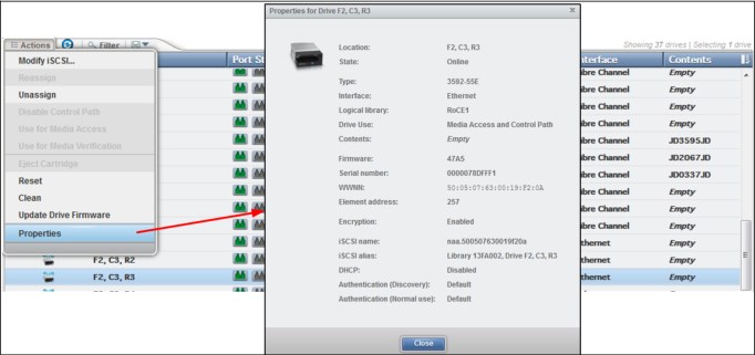
Figure 4-105 Ethernet drive property display
Resetting a tape drive
You can reset a drive by using the Drives by Logical Library page. Select the drive. Then, select Actions → Reset, as shown in Figure 4-106. The drive is unavailable for up to
4 minutes.
4 minutes.
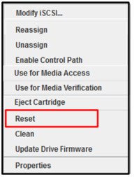
Figure 4-106 Reset the drive
Cleaning tape drives
The TS4500 tape library automatically cleans tape drives, as needed. However, you also can start a manual cleaning from the Drives page (see Figure 4-107). Select Actions → Clean.

Figure 4-107 Clean a drive
A valid cleaning cartridge is required for cleaning drives. Monitor cleaning cartridge usage from the Cartridges page. For more information, see “Viewing cleaning cartridge status” on page 249.
Updating drive firmware
When you use this action (as shown in Figure 4-108), you can select one drive to update or multiple drives of the same media type simultaneously with the firmware level that was uploaded. A drive is updated even if it is running a firmware level that is later than the version of drive code that was uploaded.

Figure 4-108 Update Drive Firmware
You can update drive firmware on one drive or multiple drives at one time. Any drives that are selected on the Drives page are updated with the firmware level that was uploaded. It is possible to install firmware levels that are earlier than the version that the drive is running.
To avoid disrupting the host, control path drives are updated when they are reset. All other drives are updated when the drive is unloaded. Control path drives must be manually reset to use the uploaded firmware level.
The drive firmware package for your workstation is available from IBM Fix Central:
From the Drives page of the TS4500 management GUI, select one or more drives, and then, click Actions → Update Drive Firmware, as shown in Figure 4-108 on page 269. The File Upload window opens. Browse to the drive firmware image and click Open.
|
Note: The LTO 8, 7, 6, and 5 drive firmware image file is named LTOZ_xxxx.fcp_fh.ro where Z is the drive type and xxxx is the firmware level. The TS1100 drive firmware image file is named xxxx_xxx.fcp_fj_D.fmrz where xxxx_xxx is the drive firmware level.
|
Monitor the status of the update in the State column and the Firmware column of the Drives table.
Select the control path drives with a state of “Reset Required” and select Actions → Reset to reset the drives.
Exporting data, logs, and statistics
Click the Save icon (diskette) to see the Export Data menu to export data from the Drives table, export service logs, or export drive usage statistics. This window is shown in Figure 4-109.

Figure 4-109 Exporting data, logs, or statistics
When you export drive usage statistics, a LIBNAME_YYYYMMDD_drive_statistics.csv file for all of the drives is exported. This file presents the number of loads, number of megabytes read and written, and number of cleanings for each drive location.
You can use this window to export service logs from a drive to send to IBM Support, if needed. Select the drive for which you want to export the logs, and then, select Export Service Logs from the Export Data menu.
4.6.2 Drives by Logical Library
Use the Drives by Logical Library page to view drive assignment and usage among all logical libraries, view cleaning cartridge status, assign drives, and manage the logical libraries and their settings. This window provides a view of the drives from a Logical Library view, as shown in Figure 4-110.

Figure 4-110 Drives by Logical Library
Monitoring drive usage
The drive usage bar indicates the current drive usage for the logical library. The number on the right side of the bar is the total number of drives that is assigned to the logical library. The bar fills as a percentage of the number of drives that is in use, as shown in Figure 4-111.

Figure 4-111 Monitor drive usage
The bar turns red if all of the drives in the logical library are being used. If all of the drives are being used frequently, the logical library might be over-allocated and you need to consider adding drives to the logical library.
The same actions can be performed on this panel as on the Drives menu. For more information about these functions, see 4.6.1, “Drives” on page 256.
4.6.3 Fibre Channel Ports
Use the Fibre Channel Ports option in the Drives menu (see Figure 4-84 on page 256) to view all of the Fibre Channel port information about drives in the library. You can view drive port status, and perform tasks, such as setting the port link speed and topology.
The selection of the Fibre Channel Ports option on the Drives menu opens a summary page of all drives and their port status, as shown in Figure 4-112.

Figure 4-112 Ports summary
The port State column is sorted by state color (green, yellow, or gray).
The gray port status icon is shown in Figure 4-113.

Figure 4-113 Gray port status icon
The gray port status icon indicates that no light is detected at the drive’s Fibre Channel port. One of the following conditions is true:
•A Fibre Channel cable is unplugged at the drive or at the nearest Fibre Channel device (host bus adapter, switch, or hub).
•A Fibre Channel cable is broken between the drive and the nearest Fibre Channel device (host bus adapter, switch, or hub).
•The drive or the nearest Fibre Channel device (host bus adapter, switch, or hub) is powered off or has a hardware problem.
•The drive is configured for as a media verification drive.
The yellow port status icon is shown in Figure 4-114.

Figure 4-114 Yellow port status icon
The yellow port status icon indicates that the Fibre Channel connections between the drive and the Fibre Channel device (host bus adapter, switch, or hub) to which it is connected are good and the port is logged into the fabric. However, communication is not established to the host application (the drive could be offline to the host application).
The green port status icon is shown in Figure 4-115.

Figure 4-115 Green port status icon
The green port status icon indicates that the Fibre Channel connections are good and communication is established.
The summary display shows the Speed and Topology columns, which include both the setting and the actual value in the following format: setting (actual).
To modify a port setting, select the port or ports that you want to modify and select Actions → Modify Speed or Modify Topology from the Ports view, as shown in Figure 4-116.

Figure 4-116 Modifying the topology and speed in the Ports view
The following setting values are valid for the topology:
•Auto-L (The drive tries Loop port (L) mode first.)
•Auto-N (The drive tries Node port (N) mode first.)
•L Port (NL)
•N Port
|
Note: The recommended setting for topology if you are connecting to an FC switch is to use either the Auto-N or N port setting.
|
The following setting values are valid for the port link speed:
•Auto
•1 Gbps
•2 Gbps
•4 Gbps
•8 Gbps
•16 Gbps for TS1160 drive only
From the Actions menu, you can display the properties of a port, as shown in Figure 4-117.

Figure 4-117 Port properties
Exporting drive connectivity report
Administrators can obtain a snapshot of their drive connections by way of the Fibre Ports page or the Ethernet Ports page in a csv file. The common use cases for the new drive connectivity report is for troubleshooting the connections between the tape library and hosts. Administrators can examine the .csv file and find which host is holding reservations along with capturing when the last I/O was performed. Figure 4-118 shows how to export the drive connectivity report from the Fibre Ports page. The Ethernet Ports page also downloads the drive connectivity report in the same location.

Figure 4-118 Exporting drive connectivity report
Figure 4-119 shows an example of what a drive connectivity report .csv file might look like. The data in the file varies per host/tape-library system.

Figure 4-119 Drive connectivity report
4.6.4 Ethernet ports
Use the Ethernet Ports option in the Drives menu (see Figure 4-120) to view all of the TS1160 model 60E and TS1155 model 55E Ethernet port information for the drives that are in the library. The window shows a summary of all Ethernet drives, such as state, IP address, iSCSI details, MAC address, and connection speed. It cannot modify any settings. For more information about exporting the drive connectivity from the Ethernet Ports page, see “Exporting drive connectivity report” on page 274.

Figure 4-120 Ethernet ports
The port State column is sorted by state color (green, yellow, or gray). The gray port status icon is shown in Figure 4-121.

Figure 4-121 Gray port status icon
The gray port status icon indicates that the Ethernet port is not initialized.
Check the following:
If no light is detected at the drive’s Ethernet port, one of the following conditions is true:
•A Ethernet cable is unplugged at the drive or at the nearest Ethernet device (host bus adapter, switch, or hub).
•A Ethernet cable is broken between the drive and the nearest Ethernet device (host bus adapter, switch, or hub).
•The drive or the nearest Ethernet device (host bus adapter, switch, or hub) is powered off or has a hardware problem.
The green port status icon is shown in Figure 4-122.

Figure 4-122 Green port status icon
The green port status icon indicates that the Ethernet port initialization is complete.
See the following line:
connections are good and communication is established.
The summary display shows information about all of the Ethernet drives, such as state, IP address, iSCSI details, MAC address and speed of connection.
From the Actions menu, you can display the properties of a port, as shown in Figure 4-123.

Figure 4-123 Ethernet port properties
4.7 Library menu
Use the TS4500 management GUI page under the Library icon to view or manage the logical libraries, as shown in Figure 4-124.

Figure 4-124 Library menu
|
Note: The Slots option is only available if the user logged in by using the service user ID or if the user has service-level access.
|
4.7.1 Advanced Library Management System
Advanced Library Management System (ALMS) is an extension of the IBM patented Multi-Path Architecture. With ALMS, the TS4500 tape library can virtualize the locations of cartridges (called SCSI element addresses) while it maintains the native storage area network (SAN) attachment for the tape drives. ALMS enables logical libraries to consist of unique drives and ranges of volume serial (VOLSER) numbers, instead of fixed locations.
The TS4500 tape library includes ALMS, so you can immediately start to assign tape drives to any logical library by using the TS4500 management GUI. Logical libraries can also be added, deleted, or easily changed without disruption. Storage capacity can be changed without affecting host applications.
ALMS offers the dynamic management of cartridges, cartridge storage slots, tape drives, and logical libraries. It enables the TS4500 tape library to achieve unprecedented levels of integration for functionality through dynamic partitioning, storage slot pooling, and flexible drive assignment.
ALMS eliminates downtime when you add capacity on demand (CoD) or high-density capacity on demand (HD CoD) storage, add or remove logical libraries, or change logical library storage allocation. ALMS also reduces downtime when you add expansion frames, add or remove tape drives, or change the logical drive allocation.
ALMS provides the following capabilities:
•Dynamic partitioning (storage slot pooling and flexible drive assignment)
•Transparent capability to add or remove storage capacity to any host application
•Capability to configure drives or storage capacity without taking the library offline
•Virtual I/O slots (always enabled) to automatically manage the movement of cartridges between I/O slots and storage slots
The TS4500 tape library complies with the SCSI Medium Changer standard. ALMS is not apparent to the application. The SCSI Medium Changer can be thought of as a “location-centric” interface.
The application that is controlling a SCSI Medium Changer device specifies a source and destination location for each request to move a cartridge. The traditional SCSI library does not have control of the cartridge locations. Instead, the SCSI library acts on behalf of the server.
Functional description
The ALMS features are described in this section.
Storage slot virtualization
The host view of a cartridge location is known as the SCSI storage element address. Without ALMS, the storage element address maps directly to a specific storage slot after the library is configured. With ALMS enabled, a specific storage element address is no longer associated with a specific storage slot. Instead, storage slots are virtualized by dynamically associating them with element addresses, as required.
An element address is associated with a storage slot that is selected by the library, as cartridges are moved and inventoried. If a storage element is empty because of a move, that source element address becomes unsolicited. The association of storage element addresses occurs in a way that is transparent to the application software.
You can select the number of storage element addresses for a logical library (as reported to the host application software) by changing the Maximum Number of Cartridges setting for that logical library with the TS4500 management GUI. For each logical library, the default value for this setting is the number of addressable storage slots that is installed in the library for that cartridge type when ALMS is first enabled or after ALMS is enabled when the logical library
is created.
is created.
|
Note: You can change the Maximum Number of Cartridges setting for each logical library, but the value must always be greater than or equal to the number of cartridges that is assigned to that logical library. The Maximum Number of Cartridges can be set to a value that is higher than the number of addressable storage slots that is installed at the time to allow future library capacity expansion to not be apparent to the host application software. However, application performance might degrade slightly because of the greater number of addresses. Be careful to not exceed the license limitations of the host application software.
|
Drive assignment
By using the ALMS flexible drive assignment capability, any drive in any position within any frame can be assigned to any logical library without creating any gaps in drive addresses. Drive (data transfer) element addresses are still mapped to specific drive locations when the drive is assigned. Any drive location can be assigned to any logical library by using the TS4500 management GUI. Each drive that is added to a logical library is assigned to the lowest available element address, regardless of the drive location.
|
Note: The intermix of models is supported within the same logical library, but only for drives of the same type. LTO drives cannot be mixed with 3592 drives, and 3592 drives cannot be mixed with LTO drives.
|
ALMS is enabled by default on the TS4500, and the data terminal equipment (DTE) addresses for any newly installed and assigned drives do not depend on the positions of the drives. The DTE address for any newly installed or assigned drive is determined by the sequence in which the drive is assigned to each logical library. With ALMS, drives are assigned to logical libraries by using the Drives by Logical Library page to assign a tape drive to a logical library on the Management Interface (MI).
With this interface, the DTE address for the first drive that is assigned to a new logical library is 256 (x'101'), as shown in Figure 4-125. The DTE address for any other drive that is assigned to a logical library is based on the next available DTE address in that particular logical library. The next available DTE address is the lowest-available DTE address after the starting DTE address. This address fills any gaps that are created when drives are unassigned and removed from a logical library.

Figure 4-125 TS4500 tape library with ALMS
When a drive is unassigned from a logical library by using the web interface, only that DTE address is made available for future usage. No other DTE addresses are affected.
Storage slot pooling
ALMS allows logical libraries to be added or deleted without disrupting operations. All storage slots are pooled (available on a first-come, first-served basis) to each logical library based on cartridge insert operations. They are a shared resource so that changes to the capacity allocation for each logical library can occur without downtime or administrator involvement.
The minimum logical library has a name only and it can be thought of as a file folder that has no contents. Drives are assigned to the logical library from the Drives page of the TS4500 management GUI. Cartridges are assigned to the logical library based on their VOLSERs and by using one of the following methods, which are listed in priority order:
•VOLSER ranges
•Software application moves from the I/O station (based on the source application that issued the command)
•Manual assignment by an operator by using the TS4500 management GUI
The primary and backup copies of the VOLSER assignment and physical location of cartridges are stored in nonvolatile random access memory (NVRAM).
Assigning VOLSER ranges
You can assign specific cartridges to each logical library based on their VOLSERs. With the TS3500 tape library, this function was known as the Cartridge Assignment Policy.
All cartridge assignments are displayed on the VOLSER range bar. As you create logical libraries and assign VOLSER ranges, any cartridges that are not part of those ranges remain unassigned. View or assign unassigned cartridges on the Cartridges page.
When you insert a cartridge into the library and its VOLSER is within a range that is assigned to a certain logical library, the cartridge is assigned to that logical library. The cartridge must be of the same media type as that logical library. For example, if you create Logical
Library 1 for VOLSERs that range from ABC000 to ABC999 (a library of LTO drives) and then you insert a cartridge with VOLSER ABC123, the library recognizes that VOLSER as belonging to the range and assigns it to Logical Library 1.
Library 1 for VOLSERs that range from ABC000 to ABC999 (a library of LTO drives) and then you insert a cartridge with VOLSER ABC123, the library recognizes that VOLSER as belonging to the range and assigns it to Logical Library 1.
If you insert a cartridge that is outside of any VOLSER ranges, it is available to import into any logical library of the same media type. The assignment is then determined by the first application to import the cartridge.
You can view all of the VOLSER ranges if you select Actions → View VOLSER ranges. You can also view all VOLSER ranges that are assigned to each logical library on the VOLSER Ranges by Logical Library page.
Virtual I/O
With ALMS, virtual I/O slots enhance the import and export capabilities of the library. With the TS4500 tape library, virtual I/O slots are always enabled so that the library automatically queues all cartridge moves between the I/O station and the storage slots. This capability makes the process of adding and removing cartridges easier and faster.
The TS4500 tape library has I/O stations with cartridge magazines so that you can import and export up to 144 cartridges at any time. The I/O slots are also known as import/export elements (IEEs). Virtual I/O slots increase the quantity of available I/O slots by allowing storage slots to appear to the host as I/O slots. These storage slots are also called virtual import/export elements (VIEEs).
With virtual I/O slots, the library automatically moves cartridges from the I/O stations to the storage slots, enhancing import and export performance, while also decoupling physical cartridge movement from the application, increasing operator efficiency.
With virtual I/O slots, the library has various mechanisms for selecting the best storage slot location for each inserted cartridge, and the best I/O station for each ejected cartridge. These mechanisms vary depending on the configuration of your library.
The VIEE temporarily takes on the attributes of an IEE until a host moves the cartridge into a storage element (StE). When the host move occurs, if the cartridge is in a storage slot, no physical move is needed and the element changes from a VIEE to an StE. Similarly, when a host exports a cartridge from an StE, the physical storage slot is reported as a VIEE without moving the cartridge to the I/O station. The library monitors when free space is available in the I/O station and moves exported cartridges when it is convenient for the library.
If a cartridge cannot be assigned, this situation is reported as Assignment Pending. This situation can occur if the assigned logical library does not have any available VIEE slots, or if all of the logical libraries do not have a common VIEE to share. To resolve this situation, free VIEE addresses so that they are available in all libraries or make a specific assignment of this cartridge to a logical library.
Library sharing
The TS4500 tape library can be configured into one or more logical libraries that can be shared by multiple applications.
The guided setup for the TS4500 tape library allows a single application to operate the library. However, often it is advantageous to be able to share a single library between heterogeneous or homogeneous applications. Certain applications (and certain servers) do not allow sharing a library between systems.
With the TS4500 tape library, you can create configurations that enable the library to process commands from multiple heterogeneous applications, such as an IBM System p application and a Windows application. With the TS4500 tape library, you can also create configurations that enable the library to process commands from multiple homogeneous applications, for example, the same application that is run by several System p servers.
Use the TS4500 management GUI to perform the following actions.
Separate libraries to separate applications
Configure the library so that it is partitioned into separate logical libraries that independently communicate with separate applications through separate control paths. This configuration (as shown in Figure 4-126) requires no special capabilities from the server or application.

Figure 4-126 Separate libraries to separate applications
Configure any single logical library (including the entire physical library) so that it is shared by two or more servers that are running the same application. Depending on the capabilities of the server and application, several ways exist to set up this type of configuration. The following methods are typical examples:
•One server to a single control path
•All servers to a single control path
•Multiple servers through multiple control paths
One server to a single control path
Configure one server (mainframe host) to communicate with the library through a single control path. All other servers send requests to that server through a network (as shown in Figure 4-127). This configuration is used by IBM Spectrum Protect.

Figure 4-127 Separate libraries to separate applications
All servers to a single control path
Configure all of the servers to communicate with the library through a single, common control path (as shown in Figure 4-128 on page 283). This configuration is used in high-availability environments, such as IBM High Availability Cluster Multi-Processing (IBM HACMP) from IBM, and Systems Management Server and Clustered Server Environments from Microsoft. Multi-initiator configurations are supported only by certain adapters and independent software vendors (ISVs). For more information, contact your vendor.

Figure 4-128 Separate libraries to separate applications
Multiple servers through multiple control paths
Configure multiple logical libraries to communicate with multiple servers through multiple control paths. This configuration (see Figure 4-129) requires that you add multiple logical libraries, and it is used by separate Backup, Recovery, and Media Services.

Figure 4-129 Separate libraries to separate applications
Your library configuration is not limited to these examples. Many configurations are possible and you can design them according to your business needs.
4.7.2 Create Logical Library window
Use this window to manage and reconfigure logical libraries, including modifying the method of encryption that is used on the logical library. Figure 4-130 shows a list of configured libraries and the window that is used to set the columns of information to display.

Figure 4-130 Logical Library main window
Using multiple logical libraries
The TS4500 tape library supports multiple libraries to share the physical library between applications or to support mixed drive types for any application.
You can create multiple logical libraries by partitioning the library’s tape drives and tape cartridges into two or more logical libraries. Each logical library consists of the following components:
•Tape drives
•Tape cartridges in storage slots
•Tape cartridges in input/output (I/O) slots
Each logical library has its own control path. A control path is a logical path into the library through which a server sends standard SCSI Medium Changer commands to control the logical library. For frames that contain LTO tape drives and frames that contain 3592 tape drives, each logical library control path is available to servers through logical unit number (LUN) 1 of the first drive that is defined within that logical library. A LUN is a number that is used by a server to identify a drive.
In a TS4500 tape library, a logical library shares empty storage slots, empty I/O slots, and the cartridge accessor on a first-come, first-served basis.
|
Note: When you name logical libraries, develop an enterprise-wide standard or convention for naming libraries for easier management of the libraries.
|
With automatic cleaning, cleaning cartridges are shared among logical libraries, so any appropriate cleaning cartridge is used to clean a drive in any configured logical library.
You can create multiple logical libraries by partitioning the physical library’s tape drives and tape cartridges into two or more logical libraries. Each logical library can contain only one media type.
Creating logical libraries
Create logical libraries by using presets that have the preferred drive and encryption configurations for their specific use. Select the Create Logical Library tab to see a selection of default logical library options, including a custom option, as shown in Figure 4-131.

Figure 4-131 Create Logical Library
Spectrum Protect
Use this option if you manage your library with Spectrum Protect.
When you select this option, 2 - 4 of the drives that are assigned to the logical library are designated as control path drives. When possible, two consecutive drives are assigned as control paths in two separate frames. This selection configures all unassigned drives to this logical library.
To configure a logical library by using the Spectrum Protect option, select the Spectrum Protect icon, then define a name, select the media drive type (LTO or 3592), and select the encryption method to use. If necessary, enter the VOLSER range to use with this logical library in the Identifier field, and select Create, as shown in Figure 4-132 on page 286.

Figure 4-132 Logical library with Spectrum Protect
If library-managed encryption is used, the key server can be set up in the security option that is described in “Encryption key servers” on page 223. Also, the key server can be added by using the Modify Encryption Method option from the Actions menu, as described in “Modify Encryption Method” on page 293.
To change drive assignments or control paths, see 4.6.1, “Drives” on page 256.
IBM Spectrum Archive
Use this option if you plan to use IBM Spectrum Archive, incorporating the Linear Tape File System (LTFS) format standard for reading, writing, and exchanging descriptive metadata on formatted tape cartridges.
When you select this option, 2 - 4 of the drives that are assigned to the logical library are designated as control path drives. When possible, two consecutive drives are assigned as control paths in two separate frames. This selection configures all unassigned drives to this logical library.
To configure a logical library by using the Spectrum Archive option, select the Spectrum Archive icon, then define a name, select the media drive type (LTO or 3592), and select the encryption method to use, if needed. Insert the VOLSER range to use for this logical library in the Identifier field and select Create, as shown in Figure 4-133.

Figure 4-133 Logical library with IBM Spectrum Archive
If library-managed encryption is used, the key server can be set up in the security option that is described in “Encryption key servers” on page 223. The key server can be added by using the Modify Encryption Method option from the Actions menu, as described in “Modify Encryption Method” on page 293.
For more information about changing drive assignments or control paths, see 4.6.1, “Drives” on page 256.
TS7700
Use this option to create a logical library for the IBM Virtualization Engine TS7700 by using all unassigned 3592 tape drives. When you select this option, up to four of the drives that are assigned to the logical library are designated as control path drives. When possible, drives are assigned as control paths in two separate frames for redundancy. The TS7700 option is shown in Figure 4-134.

Figure 4-134 Logical Library for TS7700
|
Note: The TS7700 is only supported by 3592 drive types, and the encryption method must be set to System managed. The TS7700 must run R4.0 or higher microcode.
|
General Use
Use the General Use option if you have another application to manage your TS4500 tape library and you want to use the default options.
When you select this option, one of the drives that is assigned to the logical library is designated as a control path drive. This selection configures all unassigned drives to this logical library.
To configure a logical library by using the General Use option, select the General Use icon, then define a name, select the media drive type (LTO or 3592), and select the encryption method to use, if needed. Insert the VOLSER range to use for this logical library in the Identifier field and select Create, as shown in Figure 4-135.

Figure 4-135 Logical library with General Use option
Custom
Use this option for a complete customization when you create a logical library if the presets do not fit your requirements. Use the Custom option to set library information and select the drives, VOLSER range, and maximum number of cartridges. Use this option if you are setting up multiple logical libraries.
Complete the following steps to use the Custom option:
1. Select the number of drives and slots to use for the logical library that you are configuring. Figure 4-136 shows the initial menu after you select Custom. Additionally, you can select the drive assignments, VOLSER range, maximum cartridges, and summary.

Figure 4-136 Custom logical library
2. Use the first window to define a name, select the media drive type (LTO or 3592), and select the encryption method to use, if required.
3. Use the Drive Assignment page to configure drives for the logical library, as shown in Figure 4-137. You can select all unassigned drives or select only the drives that you need. Only the unassigned drives of the type that was selected (LTO or 3592) are displayed.

Figure 4-137 Custom drive settings
4. Use the VOLSER Range page to set up a VOLSER’s range and select whether these range settings apply to only newly inserted cartridges, as shown in Figure 4-138.

Figure 4-138 Custom VOLSER range
5. Use the Maximum Cartridges page to set the number of cartridge slots that is assigned to this logical library. Also, you can use this page to configure the number of slots by using the system default, as shown in Table 4-139. The system default is the total number of slots that is licensed in the library.

Figure 4-139 Custom maximum cartridges
6. Use the Summary page to display all of your settings, as shown in Figure 4-140.

Figure 4-140 Summary
Assigning tape drives to a logical library
Each logical library requires at least one tape drive as a control path drive. Assign more tape drives, as needed, to improve performance. Enable or disable control path drives on the Drives page, as described in “Adding or removing tape drives” on page 257.
Drives are assigned to logical libraries when the logical libraries are created. You can modify the drives that are assigned to a logical library on the Drives by Logical Library page, as described in “Reassigning a drive” on page 258.
|
Note: A tape drive can be used only by the logical library to which it is assigned. Drives cannot be shared between logical libraries.
|
Assigning cartridges to a logical library
Cartridges are assigned to logical libraries based on the VOLSER range that is assigned to the logical library when it is created. For more information, see “Assigning VOLSER ranges”. You can modify the cartridges that are assigned to a logical library by modifying the VOLSER range as described in “Creating or modifying a VOLSER range” on page 253.
|
Note: Cleaning cartridges are shared among the logical libraries.
|
Assigning VOLSER ranges
You can assign specific cartridges to each logical library based on their volume serial (VOLSER) numbers. With the TS3500 tape library, this function was known as the Cartridge Assignment Policy.
All cartridge assignments are displayed on the VOLSER range bar. As you create logical libraries and assign VOLSER ranges, any cartridges that are not part of those ranges remain unassigned. View or assign unassigned cartridges on the Cartridges page, as described in 4.5.1, “Cartridges” on page 239.
When you insert a cartridge into the library and its VOLSER is within a range that is assigned to a certain logical library, the cartridge is assigned to that logical library. The cartridge must be the same media type as the media type of that logical library. For example, if you create Logical Library 1 for VOLSERs that range from ABC000 to ABC999 (a library of LTO drives), and then you insert a cartridge with VOLSER ABC123, the library recognizes that VOLSER as belonging to the range and assigns it to Logical Library 1.
If you insert a cartridge that is outside of any VOLSER ranges, the cartridge is available to import into any logical library of the same media type. The assignment is then determined by the first application to import the cartridge.
You can view all of the VOLSER ranges by selecting Actions → View VOLSER ranges. You can also view all VOLSER ranges that are assigned to each logical library on the VOLSER Ranges by Logical Library page, as described in 4.5.2, “Cartridges by Logical Library” on page 248.
Create Logical Library Actions menu
After a logical library is configured, you can use the Actions menu (see Figure 4-141) to select a configured logical library and modify it.

Figure 4-141 Logical Library Actions menu
Rename
Use the Rename option in the Actions menu to rename a logical library.
Select the logical library. Click Actions → Rename. The Rename window opens and you can enter a new logical library name.
Modify Maximum Cartridges
Use the Modify Maximum Cartridges option on the Actions menu to modify the maximum number of cartridges that is configured in a logical library. If a logical library ran out of storage capacity or new frames were added, this option can be used to increase or decrease the logical library cartridge capacity.
Select the logical library and click Actions → Modify Maximum Cartridges. The Modify Maximum Cartridges window opens and you can modify the number of cartridge slots for the logical library. If you added a storage frame, you can also use the Reset to system default option, which automatically enters the full licensed capacity of all slots in the physical library.
Modify Encryption Method
Use the Modify Encryption Method option on the Actions menu to modify the encryption method and to configure the EKM servers to use on a logical library.
Select the logical library, and click Actions → Modify Encryption Method. The Modify Encryption Method window opens so that you can set up or remove encryption from the logical library. With library-managed encryption, you can use the Modify Encryption Method page to set the EKM server IP address to use on this logical library. A drop-down list shows all of the configured EKM servers.
You can add up to four servers to the logical library, as shown on Figure 4-142. You can use this page to add a new unlisted EKM server IP address and to test it by clicking Ping.

Figure 4-142 Modifying the encryption method
Apply VOLSER Ranges
Use the Apply VOLSER Ranges option on the Actions menu to reassign all cartridges based on VOLSER ranges. This action can be useful in the following scenarios:
•If cartridges with old policies that do not match the current assignments are in the library
•If a VOLSER range was moved to a different logical library, or the range was resized and the option to reassign cartridges was not selected
•If a cartridge was manually assigned outside of a VOLSER range
Cartridges are reassigned to existing logical libraries. If the maximum number of cartridges is met for a logical library, any other cartridges that were assigned to that logical library are unassigned.
Eject All Cartridges in Drives
Use the Eject All Cartridges in Drives option in the Actions menu to eject all cartridges from all drives in a logical library. Use this option only if the cartridges cannot be ejected by the application.
Reset Control Path Drives
Use the Reset Control Path Drives option on the Actions menu to reset all control path drives that are configured on a logical library.
This option removes all paths on the selected logical library to the TS4500 for the time that it takes to reset the control path drives.
Delete
Use the Delete option on the Actions menu to delete the logical library.
To delete a logical library, you must perform the following tasks:
•Unassign all drives (see “Unassigning a drive” on page 258)
•Delete all VOLSER ranges (see “Delete a VOLSER range” on page 254)
•Unassign any cartridges that are assigned (see “Assigning or unassigning cartridges” on page 250)
After you complete these actions, select the logical library to delete. Click Actions → Delete and follow the instructions on the window.
Properties
Click Actions → Properties to display detailed properties about the selected logical library, as shown in Figure 4-143.

Figure 4-143 Properties
4.7.3 Slots
The Slots option is available for a user with service-level access. Use the Slots option to set storage slots online or offline.
This option is normally used by the IBM service support representative (SSR) for setting slots offline and then online during a service action. This option can also be used to set any slot online and offline for problem determination.
To set slots offline or online, select the frame, row, and slot number from the menu, as shown in Figure 4-144, and then select either the Set Online action or the Set Offline action.
Single or multiple slots can be selected and the number that was selected is displayed in the upper-right corner of the menu.

Figure 4-144 Slots
4.8 Monitoring
The TS4500 management GUI pages under the Monitoring icon can help you to monitor the system, events, and tasks, as shown in Figure 4-145.

Figure 4-145 Monitoring
4.8.1 System
The System page, as shown in Figure 4-146, displays the physical configuration of your TS4500 tape library. Start at this page to identify health and status issues with the library and library components.

Figure 4-146 System
Viewing component status
View the status of the library frames, storage slots, tape drives, I/O stations, and the cartridge accessors on the System page.
Hover over the top of a frame, or over an I/O station, to view its state and contents, as shown in Figure 4-147.

Figure 4-147 Component status
If a problem occurs with any of the components, a warning or error icon is displayed. Hover over the icon to see a message about the affected component that includes the amount of time that passed since the event occurred and a short description of the event. Go to the Events page to view the detailed information about the error or warning.
Library frame
An error or a warning icon at the base of a library frame indicates a problem with the frame door, I/O station (if applicable), or with any of the slots, cartridges, or drives in that frame.
Cartridge accessor
An error or a warning icon on the cartridge accessor indicates a degraded state of operation for the accessor or an issue with any of the accessor components (gripper, scanner, or calibration sensor).
I/O station
Click an I/O station to view the I/O station properties, including the state of the I/O station. The possible states are empty, cartridges in I/O for 60 minutes or more, or a magazine that is missing for 60 minutes or more. Icons on the door of the library frame also indicate the I/O station status. Each icon is described next.
What do the icons mean
The System page shows a graphical representation of your library. The icons provide basic status and event information. Hover over error and warning icons to view the length of time since the event was generated and a short description of the event.
Table 4-7 lists each icon.
Table 4-7 Status icons
|
Icon
|
Description
|
 |
An error occurred with a frame, tape drive, cartridge, or accessor. Hover over the icon to see a list of the most important issues that cause this state. Click any issue to open the Events Page to see more information.
|
 |
A warning occurred with a frame, tape drive, cartridge, or accessor. Hover over the icon to see a list of the most important issues that cause this state. Click any issue to open the Events page to see more information.
|
 |
The Tasks icon shows whether tasks are running.
|
 |
The Alerts icon shows whether alerts exist.
|
 |
The I/O station is full.
|
|
|
The I/O station is full for 60 minutes or longer.
This situation might occur with input operations if a shortage of storage slots exists. This situation also might occur with output operations if the I/O station is unattended. View the state of the cartridges, I/O slot (import queued), or I/O slot on the Cartridges page.
|
|
|
The I/O station is partially full.
|
|
|
The I/O station is partially full for 60 minutes or longer.
This situation might occur with input operations if a shortage of storage slots exists. This situation might occur with output operations if the I/O station is unattended. View the state of the cartridges, I/O slot (import queued), or I/O slot on the Cartridges page.
|
|
|
The I/O station is empty.
|
|
|
The cartridge magazine is missing.
|
|
|
The cartridge magazine is missing for 60 minutes or longer.
|
Frame selection
The main System status display shows up to four frames at a time. Use the mouse to select the four frames that you want to display from the System status display window, as shown in Figure 4-148.

Figure 4-148 Frame selection
Status pods
Status pods at the bottom of the System page show a quick view of the capacity, drive use, and logical library health status, as shown in Figure 4-149.

Figure 4-149 Status pods
Physical capacity status pod
The physical capacity pod displays how many licensed slots are filled by cartridges in this tape library. In a mixed media library, you can select to display a summary of either LTO or 3592 slots by using the selector button on this pod.
The pod is green when the number of cartridges in the library is fewer than the number of licensed slots.
The pod is yellow when the physical capacity exceeds the capacity use threshold. If this situation occurs, you can remove cartridges or purchase additional capacity.
The pod is red when the number of cartridges exceeds the number of licensed slots. If this situation occurs, you must remove cartridges or purchase additional capacity.
Drive use status pod
The drive use status pod displays the status of the drives across the library. Click the status pod to go to the Drives by Logical Libraries page.
The blue pod fills as the number of drives (in use out of the total number of drives in the library) increases.
If multiple logical libraries exist, a warning icon displays if all of the drives in any logical library are in use.
Health status pod
The color of the health status pod indicates the current state of the library by severity. Click the status pod if the pod is yellow or red to go to the correct page so that you can understand and troubleshoot the warning or error. If a library is in more than one state, the higher priority state is shown.
Actions and remote management of the library
Use the Actions menu on the upper-left corner of the page, or right-click a frame or I/O station (see Figure 4-150). The menu of available actions changes depending on whether the entire library, a specific frame, or an I/O station is selected.

Figure 4-150 Actions menu
You can use certain actions on the System page to perform physical actions on the library remotely. For example, you can open and close I/O station doors from the I/O station Actions menu. You can turn on or turn off the beacon light-emitting diode (LED) from the Actions menu of any frame with an I/O station. You can use the beacon LED to signal remotely to operators the frame that requires attention or the I/O station that contains a specific cartridge. For more information, see “I/O stations” on page 40.
Running an inventory
An inventory operation (see Figure 4-151) includes a check to determine whether each cartridge storage slot in the library is empty or full. It is followed by a scan of the bar code labels. An inventory can be run on a single library frame or an entire library.

Figure 4-151 Inventory
The TS4500 tape library automatically inventories the library. However, certain conditions necessitate that you manually start an inventory. For example, if an automatic inventory of the media was inconsistent, you might need to run an inventory to reconcile an inconsistency. Similarly, you might need to start a manual inventory if the host application software indicates that a problem exists with the library inventory.
The TS4500 tape library provides two inventory options, as shown in Figure 4-152.

Figure 4-152 Inventory Frame
Select the type of scan that is required:
•Scan tier 0 and tier 1
Use this option when a faster inventory is preferred. This option scans other tiers only if a discrepancy is identified.
•Scan all tiers
Use this option when a full library inventory is required. This option is not concurrent, and it can last many hours, depending on the number of cartridges in the library.
|
Note: The depth of a cartridge location in a HD slot is known as a tier. Frame drive side slots are for the cartridges that are immediately accessible in an HD slot (these are Tier 1 cartridges). Behind that is Tier 2, and so on. The maximum tier in an LTO HD slot is Tier 5. The maximum tier in a 3592 HD slot is Tier 4. The single slots on the door-side of a frame are referred to as Tier 0 slots.
|
When no frame is selected, select Inventory from the Actions menu to start an inventory of the library. When a frame is selected, the Inventory option inventories only that frame. Right-click any frame and select Actions → Inventory to inventory only that frame.
You can inventory a single frame by selecting it and then clicking Actions → Inventory. If you do not select a frame, all frames are inventoried.
Inventory all tiers
In a high-density (HD) library, a standard inventory is a scan of tier 0 and tier 1. However, at certain times, it is necessary to inventory all tiers. This operation takes more time because it requires moving the cartridges within an HD slot to scan each bar code. For all inventory operations, tier 2 and higher in an HD slot are only scanned when one of the following changes occurs:
•A tier 1 cartridge bar code label changed, which is detected during inventory. Only the slots for which the tier 1 label changed are audited.
•Enough tier 1 bar code labels changed in a column to warrant an audit of the entire column of HD slots.
•An “Inventory all tiers” is requested through the TS4500 management GUI.
|
Important: We suggest that you limit the manual access of HD slots to the initial bulk loading of the frame because of the length of time that is required to complete a full inventory with an audit.
|
Typically, the following time frames are required for the TS4500 tape library to audit cartridges:
•Less than 30 seconds for each HD slot
•Up to 10 minutes to inventory a column of full HD LTO slots
•Up to 8 minutes to inventory a column of full HD 3592 slots
•More than 45 minutes to perform a full inventory with an audit on a single HD frame, depending on the frame type
Reset Library
You can reset the TS4500 tape library control system if the library experiences a stopped state. This action (see Figure 4-153) resets the node cards in the library.

Figure 4-153 Reset Library
A reset can take up to 3 minutes. A reset might require you to reconnect to the web server after the reset completes.
Rename the library
You can rename the library by using the Actions menu and by selecting Rename, as shown in Figure 4-154.

Figure 4-154 Rename the library
Turn on or turn off the beacon LED
Each frame with an I/O station has a beacon light-emitting diode (LED) that can be turned on or turned off. You can use the beacon LED to identify a frame that is in service or needs service, or to identify a frame for other reasons.
Select a frame with an I/O station. Then, select Actions → Turn On Beacon or Actions → Turn Off Beacon, as shown in Figure 4-155.

Figure 4-155 Turning on or turning off the beacon
Updating library firmware
Use the Firmware Update option on the Actions menu to nondisruptively update the library firmware to use the latest library enhancements. You can also use this option to update the drive firmware.
Use the TS4500 tape library to update library firmware without scheduling downtime and without interrupting the job flow or reducing productivity.
A TS4500 tape library firmware upgrade is generally performed by the IBM service support representative (SSR) if the update fixes a field issue or if the update is suggested by IBM. For client-initiated requests, the upgrade is the responsibility of the client. Contact your IBM SSR with any questions about a specific scenario, who is responsible for the upgrade, and whether a charge is associated with the upgrade.
Update procedure
Obtain the library firmware package from IBM Support or from IBM Fix Central at the following website and install the package on your workstation:
Complete the following steps to update the firmware:
1. From the System page of the TS4500 management GUI, select Actions → Firmware Update, as shown in Figure 4-156.

Figure 4-156 Firmware Update
2. On the File Upload window, browse to the library firmware image and click Open, as shown in Figure 4-157.

Figure 4-157 File Upload
|
Note: The library firmware image file is named TS4500_WXYZ.afwz, where W, X, Y, and Z are different numbers or letters, depending on the firmware version.
|

Figure 4-158 Firmware update confirmation
4. The firmware is downloaded to the TS4500 tape library first, and this download can take a few minutes. Then, the update starts and the Tasks pod, which is at the lower-left corner of the System page, indicates that the firmware update task is in progress. Monitor the status of the update from the Tasks page by selecting Monitoring → Tasks, as shown in Figure 4-159.

Figure 4-159 Firmware update status
5. You lose connection after the firmware is upgraded. Log back in to the TS4500 tape library and select Actions → Events to display the status of the update.
|
Note: If the library firmware update stops, nondisruptively reset the library from the System page by selecting Actions → Reset Library. Then, try the firmware update again.
|
Downloading the statistics and logs
Click the Save icon (highlighted) on the toolbar to view a list of available downloads, including library logs, component usage statistics, and library configuration information, as shown in Figure 4-160.

Figure 4-160 Export files
The following files are available for download and export:
•Library logs: This option downloads a .zip file that includes event logs, servo logs, nonvolatile random access memory (NVRAM) event logs, and Fatal Exception logs.
•Library Logs to IBM. This option downloads service logs direct to the IBM ECUREP host using the call home functionality on the IMC/TSSC.
•Usage statistics: This option downloads a comma-separated value (.csv) file that contains the usage statistics of important library components.
•System summary: This option downloads a .csv file that lists the library properties and configuration settings. The downloaded file name uses the following format where libraryname is the name that you set for the library. The file name format is libraryname_YYYYMMDD.csv.
|
Note: It is helpful to download this file periodically to compare the library configuration over time or to retain the configuration for auditing purposes.
|
4.8.2 Events
Events are informational notices, warning alerts, and error alerts that provide more information about the library and library components. Use the Events page to view these events and to monitor their status.
Event categories
Error, warning, and information-only events are displayed on this page. The events are defined in order of severity.
Error
The error icon is a red circle that contains a white X. The error icon is shown in Figure 4-161.

Figure 4-161 Error
Error events are the highest priority events, and they require immediate intervention. They are identified by the error icon (a red circle that contains a white X) in the Events table. Errors indicate a hardware or communication failure that can impair library operations or damage the system.
Warning
The warning icon is a yellow triangle that contains an exclamation mark, as shown in Figure 4-162.

Figure 4-162 Warning
Warning events are the second-highest priority events, and they require attention when time allows. They are identified by the warning icon (a yellow triangle that contains an exclamation mark) in the Events table. Warnings indicate a problem that does not pose an immediate threat, but warnings require resolution to ensure that library operations continue smoothly.
Information
The information icon is a blue balloon that contains the lowercase letter i, as shown in Figure 4-163.
Figure 4-163 Information
Informational events are the lowest-priority events, and they do not require corrective action. They are identified by the information icon (a blue balloon that contains a lowercase letter i) in the Events table. Information-only events provide information about the library or library operations, such as the user login and tape movements.
Monitoring events
The events that are displayed on the Events page are sorted first by severity and second by time. If the Events table is full and a new event is generated, the oldest, inactive events are deleted first. The events table can be limited to show events for 1 day, 1 week, or all. Shown in Figure 4-164 is the Events table.

Figure 4-164 Events
Active events, which are displayed in color in the Events table, are events that are not yet fixed. Inactive events, which are displayed in gray in the Events table, are events that are being addressed or events that are fixed. Use the Actions → Mark Inactive option to manually mark an event as inactive. Events can also be marked as inactive manually by an IBM SSR.
Only errors and warnings can be marked as inactive. Information-only messages are not alerts, and they cannot be marked as inactive.
Select Actions → Properties when a specific event is selected to view details about the event. The Event Properties window includes a complete history of the event. If an action can be performed to resolve an error or warning event, a fix procedure is also provided, as shown in Figure 4-165.

Figure 4-165 Event details
View the status of each event in the State column. For events that require service, the State column shows when a Call Home is generated, when the Call Home is complete, and when the service action is complete.
If SNMP traps are enabled, notification messages are also sent to the SNMP server based on the subscription level (error, warning, or information). Select Notifications from the Settings page to manage SNMP traps and subscriptions.
Monitoring tape cartridge moves
Tape cartridge moves are displayed as information events. The default table sort displays all information events last. Sort by location to see a history of moves by drive, I/O station, or storage slot. Sort by time to see the most recent moves, moves on a specific date, or moves at a specific time.
Monitoring when tapes are moved, and where they are moved to and from, can be helpful to view overall library activity. This view can also help you diagnose recurring problems if you use a filtered view of the Events table to display the most recent actions with any component.
Events at a glance
If any events are active, the Events icon displays in the lower-right corner of the System page and the Events page. The number next to the icon indicates the total number of active alerts (both errors and warnings). The color indicates the highest level of the active alerts. If the number is in a red circle, at least one of the indicated alerts is an error (see Figure 4-166). If the number is in a yellow circle, the most severe active alert is a warning.

Figure 4-166 Events
Hover over the Events pod to see the location of the event, the relative time since the event occurred in days (d.), hours (hr.), and minutes (min.), and a short description of the event.
Monitoring tasks
The Tasks page displays long-running actions, such as inventory and reset, that run in the background while the library performs other operations. Use this page to monitor the progress of tasks and to view task properties.
The Tasks table displays all active tasks. They are sorted first by state and second by time. Tasks are removed from the table after a certain amount of time when they expire.
Highlight a task in the table, and select Actions → Monitor to view the status of the task, as shown in Figure 4-167.
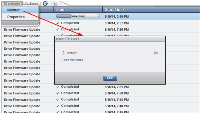
Figure 4-167 Task monitoring
Highlight a task in the table and select Actions → Properties to view a complete description of the task and the task history, as shown in Figure 4-168.
|
Note: If a long-running task stops or appears to take more time than necessary, you can reset the library and then start the task again. You can nondisruptively reset the library by selecting Actions → Reset from the System page to reset the library.
|

Figure 4-168 Task Properties
The Tasks pod displays in the lower-left corner of the System page when tasks are running. The number next to the Tasks pod indicates the number of tasks. If no icon is displayed, no tasks are active. Hover over the Tasks pod to see the three oldest running tasks that are sorted in the time sequence that they were created, as shown in Figure 4-169.

Figure 4-169 Tasks pod
4.9 Tape System Library Manager
Tape System library Manager (TSLM) software provides consolidation and simplification benefits in an IBM TS4500 tape library environment.
TSLM provides a resource management layer between applications, such as IBM Spectrum Protect, and the tape library hardware. TSLM decouples tape resources from applications. This capability simplifies the aggregation and sharing of tape resources.
TSLM can combine the capacity of multiple TS4500 and TS3500 libraries into a single reservoir of tape storage that can be managed from a single point. This capability allows more effective management, monitoring, and reporting of the use of tape storage resources for new and existing TS4500 and TS3500 systems.
TSLM is software that is designed to exceed today’s tape storage management challenges for various clients that are involved in High Performance Computing (HPC) environments, such as oil and gas exploration and genomic analysis, where dozens of tape libraries and hundreds of tape drives must be shared and managed to back up and archive petabytes of data at the lowest cost possible.
The IBM TS4500, IBM TS3500, IBM Tape System Library Manager, and IBM Spectrum Protect are the ideal solutions for these clients.
TSLM provides the following benefits:
•Consolidated, mainframe-class media management services
•Centralized repository, access control, and administration
•Management beyond physical library boundaries:
– Access to multiple TS3500 or TS4500 tape libraries as a single library image.
– The libraries can be separate (at SAN distances) or connected in a shuttle complex (TS3500 tape library only).
•Dynamic sharing of resources across heterogeneous application boundaries
•Security features to allow or prevent application access to tapes:
– Helps to enable a common scratch pool and private pools for every application.
– Secures the usage and visibility.
•Policy-based drive and cartridge allocation
•Policy-based media lifecycle management
•3494 emulation
Emulation of an IBM 3494 library on top of an attached IBM TS3500 or TS4500 tape library.
For more information about TSLM, see IBM Tape System Library Manager User’s Guide, GA32-2208:
4.10 Remote support
Remote support for the TS4500 tape library involves the use of a Call Home feature to detect and solve problems. Also, remote support requires several important security functions.
Optional remote support is available for the TS4500 tape library through its Call Home capability. The Call Home feature uses the integrated management console (IMC) to report failures that are detected by the library or a tape drive. Whenever a failure is detected, Call Home sends detailed error information to IBM Support.
The IBM service support representative (SSR) can then prepare an action plan to handle the problem before the SSR travels to the library. The library might also periodically send support information, such as configuration, library, and drive code versions and error logs, to IBM.
The Call Home feature of the TS4500 tape library has three different, but related, capabilities: Problem Call Home, Heartbeat Call Home, and Test Call Home. The TS4500 tape library sends data files that might be helpful to IBM Support Center personnel for all three types of Call Home functions. These data files include library error logs and configuration information, such as the Machine Reported Product Data (MRPD) log. The MRPD file contains the following information about the machine (library):
•Number of frames and drives
•Model and serial number of each frame
•Type and serial number of each drive
•Code version of the library and each drive
•Any machine-detectable features, such as extra I/O stations and capacity expansion
If a Problem Call Home is initiated, the library also sends the tape library logs and drive logs that relate to the problem.
Problem Call Home
The TS4500 tape library or one of its drives detects a problem and the library initiates a Call Home operation. This Call Home operation creates a problem management record (PMR) in the IBM Remote Technical Assistance Information Network (IBM RETAIN). This single page of text data can help the IBM Support Center or SSR determine an action plan and a list of parts, which are called field-replaceable units (FRUs).
Heartbeat Call Home
The TS4500 tape library sends the Heartbeat Call Home on a scheduled basis to ensure that the Call Home function operates correctly. By default, the Heartbeat Call Home is sent once a week, 1 hour after a power cycle, and 1 hour after a code update completes. The frequency of Heartbeat Call Home is set on the service menu as shown in Figure 4-170.
A service user is requred to access this option.

Figure 4-170 Call home settings
Test Call Home
When the SSR services the library, the SSR can issue a Test Call Home operation to RETAIN from the TS4500 management GUI. Through the library, the SSR can include drive dumps in the Test Call Home for analysis. In this way, a drive dump can be accessed by IBM Support Center personnel through the Call Home database.
4.10.1 Remote support through a system console
A system console is a service tool through which the TS4500 tape library provides remote support. The integrated management console (IMC) can be used as a service console with the TS4500 tape library. Similar in function to the IBM TotalStorage System Console (TSSC), the IMC comes installed with a set of software tools to help with both the local service and remote support of the attached TS4500 tape library.
Table 4-8 lists the system console features that can be ordered for the library.
Table 4-8 System console and remote support features
|
Feature code supported models
|
Supported models
|
Client setup unit
(CSU)
|
Description
|
|
2704
|
D25, D55, S25 S55, S24, and S54
|
No
|
Console expansion 26-port Ethernet switch, rack mount
|
|
2715
|
L25 and L55
|
No
|
TSSC Console attachment
|
The default method that is used by the library for Call Home support is a broadband connection that uses the Electronic Customer Care (ECC) Call Home function through the system console.
To perform an ECC Call Home operation through a system console, the TS4500 tape library sends Call Home information across a private Ethernet connection to the system console. The system console then performs the ECC Call Home operation and sends the information to IBM Remote Technical Assistance Information Network (RETAIN) through the system console’s modem or Ethernet (broadband) connection.
The IMC is preconfigured for remote support with the TS4500 tape library. The IMC also comes equipped with a RJ45 port that can be used to connect an external network cable for remote support.
Table 4-9 lists the capabilities of remote support with a system console.
Table 4-9 Remote support capabilities
|
Location
|
Event support
|
Support
|
|
Client site
|
Call Home events
|
•Error initiated
•Heartbeat (regular interval)
•Test
|
|
System console support capability
|
•Error-initiated problem reporting for up to 43 subsystems
•Staged, error-specific data gathering
•Subsystem and system console heartbeat reporting
•Wellness checking
•Log file storage (daily)
•Code image and documentation repository (from media and RETAIN Fix Distribution Library)
|
|
|
System console and remote support service tools
|
•Code image broadcast
•Call Home event log review
•End-of-call completion report
|
|
|
IBM Support
|
System console remote access
|
•Authenticated, secure remote access
•Simultaneous call in and Call Home
•Data transmission (Transmission Control Protocol/Internet Protocol (TCP/IP)) supported
|
|
IBM Call Home database
|
•Always available (24x7) access by IBM Support staff
•Error analysis and search capability
|
4.10.2 Remote support security
The system console provides Ethernet connectivity through a private internal network. This section describes the security design for remote support of the network-attached devices.
The system console also provides optional Ethernet outbound connectivity through the client’s network to the IBM service support system, RETAIN. All inbound communication over this connection is restricted. The system console uses the following protocols to port numbers:
•HTTPS: Port 443
•HTTP: Port 80
•Domain Name System (DNS): Port 53
For outbound and bidirectional data to and from RETAIN, the system console uses the ports (by default) that are listed in Table 4-10. You can modify the port numbers by using the TS4500 management GUI.
Table 4-10 Default system console ports for outbound and bidirectional data to and from RETAIN
|
Port
|
Type of data
|
Direction
|
Protocol
|
|
67/68
|
Dynamic Host Configuration Protocol (DHCP)
|
Outbound
|
User Datagram Protocol (UDP)
|
|
80
|
HTTP
|
Bidirectional
|
Transmission Control Protocol (TCP)
|
|
161/162
|
SNMP
|
Outbound
|
TCP
|
|
443
|
Secure Sockets Layer (SSL)
|
Bidirectional
|
TCP
|
|
1443
|
IBM Security Key Lifecycle Manager for z/OS (SKLM) server
(library-managed encryption (LME) only)
|
Outbound
|
TCP
|
|
3801
|
IBM SKLM server (LME only)
|
Outbound
|
TCP
|
|
389
|
Lightweight Directory Access Protocol (LDAP)
|
Bidirectional
|
TCP and UDP
|
|
636
|
LDAP
|
Bidirectional
|
TCP and UDP
|
|
443
|
HTTPS
|
Bidirectional
|
TCP
|
Dial-out security features of the IMC
Dial-out is used by the Call Home feature to send service-related information from the attached systems to the IBM service support system. The following dial-out security properties are available for the attached systems:
•Dial-out is from the client location to the IBM connection point. The IBM service support system (RETAIN) does not initiate connections to the attached systems.
•Dial-out through the system console is over an outbound Ethernet connection to the client network. All outbound traffic is limited to HTTP, HTTPS, and Domain Name System (DNS) information. All service-related data is communicated by using HTTPS, and it is encrypted.
•The data that is exchanged between the attached systems and RETAIN is service-related data. The protocol that is used is specific to this application and not publicly available.
•On the first data exchange of each transmission, RETAIN validates that the calling system is entitled to service. If the calling system is not validated, it is disconnected.
•The default setting for the Call Home feature is enabled. The Call Home feature can be disabled by an IBM SSR.
None of the client data that is stored on the tape or in memory for the TS4500 tape library is transmitted or accessed in a Call Home session. Call Home is enabled or disabled through the service menu of the TS4500 management GUI. When Call Home is correctly configured, Call Home uses an IBM Global Services secure network or an internet connection. A unique account code is used that establishes connections only to RETAIN.
Dial-in security features of the IMC
Dial-in is used by IBM support to log on to the system console and provide service support. All dial-in connectivity to the system console is through a broadband connection, which restricts all incoming traffic. Separate logon IDs are required for access to each attached system.
|
Note: The TS4500 tape library does not support dial-in. Only the IMC/TSSC supports dial-in.
|
The system console supports the following data security requirements when the system console is configured correctly:
•Client data, which is stored on tape or in memory, cannot be transmitted or accessed in remote support sessions.
•Remote dial-in is enabled or disabled by the client by using the TS4500 management GUI. Remote dial-in is disabled, by default. When remote dial-in is enabled, it is enabled for
24 hours, by default.
24 hours, by default.
•Remote dial-in requires a password for access. The password is managed by the client. The default setting for dial-in is to not require a password. A password can be specified by the client and set by the IBM SSR.
|
Note: Because the IMC and TSSC both run system console code, all of the TSSC functions are integrated into the IMC. The security requirements for the IMC are the same as the security requirements for the TSSC.
|
Port information for firewall environments
Table 4-11 lists the only ports that are required to be opened on the firewall for environments where the tape configuration is separated from the LAN-attached hosts and web clients by a firewall. All other ports can be closed.
Table 4-11 TS4500 default port information for firewall environments
|
Function
|
Port
|
Direction (from library)
|
Protocol
|
|
Library operations
|
3494
|
Bidirectional
|
TCP
|
|
TotalStorage Specialist
|
80
|
Inbound
|
TCP
|
|
SNMP traps
|
161/162
|
Bidirectional
|
UDP
|
|
Encryption Key Manager
|
1443
|
Outbound
|
SSL
|
|
Encryption Key Manager
|
3801
|
Outbound
|
TCP
|
|
LDAP
|
389
|
Bidirectional
|
TCP and UDP
|
|
LDAP
|
636
|
Bidirectional
|
TCP and UDP
|
|
Kerberos
|
88
|
Bidirectional
|
TCP and UDP
|
|
HTTPS and SSL
|
443
|
Bidirectional
|
TCP
|
|
Note: The system console uses the following ports:
•HTTPS: Port 443
•HTTP: Port 80
•DNS: Port 53
|
Port information communications can be initiated by the tape library or by the host. Typically, the library initiates a connection only when it is responding to the host. However, in unsolicited messages, such as statistics notifications and operator interventions, the library initiates a connection through port 3494. If the library needs to make a connection to the host, the library chooses a temporary port and uses that port to make an outbound connection to a 3494 listening port on the host.
When the host has a message to deliver to the library, the host chooses its own ephemeral port by which to make an outbound connection to listening port 3494 on the library manager. The connection is only maintained for the duration that is required to pass a single message, and then the connection is disabled.
Table 4-11 lists the minimum level of connectivity that is required to perform library operations. The following ports can be opened on the firewall, but they are not necessary for full functionality:
•The standard HTTP port, 80, allows inbound communication to the library from the TS4500 management GUI.
•Ports 161 and 162 are the standard ports for sending SNMP traps. SNMP traps can be sent from the TS4500 tape library or from the IMC. The tape library can be configured to send traps to SNMP target machines. In this case, the firewall needs to allow outbound connections from the library from its port 161 to port 162 on the listening SNMP target machine.
Figure 4-171 shows all of the external communication connections to the TS4500 tape library control system.

Figure 4-171 External communication connections to the TS4500 tape library control system
The host interface is provided by the drives. The library communicates with the drives through the Library/Drive Interface. The Ethernet port and modem port do not have any direct access to the Library/Drive Interface. All communication between the various interfaces is through the library control system.
All library communication requires explicit support by the library firmware that is running in the library control system. The library firmware does not provide capability for any of the following functions:
•Communicating between the Ethernet port and the TS4500 management GUI
•Communicating between the TS4500 management GUI and the modem port
•Accessing data from tape cartridges through the Library/Drive Interface
•Sending or receiving data from tape cartridges through any port
Security considerations with the TS4500 management GUI
Remote support security for the TS4500 tape library through a system console when you use the management GUI is described.
The management GUI does not allow any access to client data, and it does not allow File Transfer Protocol (FTP) or Telnet type operations. It provides only those functions that are specifically coded in the library firmware. The only files that it can offload are library logs, drive logs, and certain usage and error statistics files. It cannot be used to read or write a client cartridge or otherwise access client data.
The management GUI allows the client to set up an administrator password that is required to use the management GUI to perform any library task. The management GUI also provides several levels of access through various preset roles.
The following list presents potential security concerns when you use the management GUI:
•A management GUI user might move a cartridge from one location to another location within the library, potentially confusing a host application or making a cartridge unavailable by moving it to a different partition.
•A user can reconfigure the library, possibly causing problems at the hosts because of changes in partitioning or device IDs.
•A remote user can update library or drive firmware. However, because the library and drives ignore any firmware that they do not recognize, the only exposure is to loading firmware that is not the latest level.
These security concerns can be addressed by using the password, user role, and authentication features that are provided by the management GUI, and also by enabling SNMP audit logging. When SNMP audit logging is enabled, the library sends notifications when certain events occur in the library.
For more information about security and firewalls that are used to connect the TS4500 and IMC to your local network for Call Home and remote support, see IBM Data Retention Infrastructure (DRI) System Connectivity and Security:
..................Content has been hidden....................
You can't read the all page of ebook, please click here login for view all page.