


IBM TS4500 tape library
The IBM TS4500 tape library is a storage solution that is designed to help midsize and large enterprises respond to storage challenges. Several of these challenges include the high data volume, growth in data centers, increasing cost of data center storage footprints, difficulty migrating data across vendor platforms, and increased complexity of IT training and management as staff resources shrink.
The TS4500 tape library combines reliable, automated tape handling and storage with high performance in an open systems and enterprise environment. Incorporating the IBM Linear Tape-Open (LTO) Ultrium tape and 3592 drives, the TS4500 tape library offers outstanding retrieval performance with typical cartridge move times of less than 3 seconds.
The TS4500, installed with the High Availability (HA) option, provides dual active accessors for redundancy and can double the robot performance during tape move operations. The HA option on TS4500 has no dedicated service bays and provides the Elastic Capacity option for the use of the storage slots in these integrated service bays.
The TS4500 tape library can be deployed as a single frame library and upgraded to a maximum of 18 frames, with a combination of LTO and 3592 frames. This single frame library can be partitioned into multiple logical libraries. This feature makes the TS4500 tape library an excellent choice for consolidating tape workloads from multiple heterogeneous open systems servers.
The TS4500 protects investment by providing for redeployment of S24 and S54 frames from the TS3500 onto the TS4500.
The library provides outstanding reliability and redundancy through the provision of redundant power supplies in each drive frame, control and data path failover, dual grippers within the cartridge accessor, and dual active accessors. Library and drive firmware can be upgraded nondisruptively, without interrupting normal operations.
Encryption is available for all supported drives. The following encryption methods are supported:
•Application-managed encryption (AME)
•Library-managed encryption (LME)
•System-managed encryption (SME) for IBM z/OS TS7700 support
TS4500 Release 8 added the following functions:
•3588-F9C (LTO9 FC Multi Mode) Drive Support
•3588-F9S (LTO9 FC Single Mode) Drive Support
•3588-S9C (LTO9 SAS) Drive Support
•TLS support for GKLM
•REST support for accessor speed adjustment
•REST support for moving cartridges (moveToSlot, moveToDrive, and moveToIOStation)
•REST support to request specific log files from the library
•REST support for reporting frame door open/close transitions as attributes rather than states
•REST support for querying the state of all slots or using a location parameter
•REST support for scannerFailed state for Accessors resource
•REST support for accessible attribute for Drive and Cartridges resources
•REST support for internalAddress attribute for Cartridges resources and ability to move all cartridges types to I/O station
•REST support for new tasks of calibrateFrame and calibrateLibrary
•REST support for new attributes of GET /v1/reports/drives for drive clean
TS4500 Release 7 added the following functions:
•TS1160 model 60S
•Support for rear door open detection and reporting (each frame requires plant feature code 4892)
•Activity log on GUI System Summary
•REST support for data cartridges, frames, and reports
•An option for a new 5U top rack frame, 3584 Model TR2, which provides an extra 5U of rack space on any frame in a library without requiring more floor space.
TS4500 Release 6 added the in-band method for sending REST API commands and receiving HTTP responses by using SCSI Write Buffer and Read Buffer commands, respectively. The method is called REST over SCSI (RoS).
TS4500 Release 5 added the following functions:
•TS1160 model 60E
•TS1160 model 60F
•Fibre Channel connectivity report
TS4500 Release 4 added the following functions:
•TS1155 model 55E
•TS1155 model 55F
TS4500 Release 4.1 added the LTO Ultrium 8 tape drive (Model 3588 F8C) function.
TS4500 Release 3 added the following functions, which are described in this chapter:
•HA with dual active accessor and Elastic Capacity option
•Mainframe-ready for TS7700 attachment
•Integrated TS7700 Backend Switches
•Support for external TSSC/Integrated management console (IMC)
•Flexible growth options with new flex track design
•Support for 4 EKM servers on each logical library
With TS4500 Release 2, the following new functions are supported over and above the first release:
•Automatic media verification
•Flexible remote authentication
•Primary control system failover
•Mixed media types within the same TS4500 library
•Scalability to 18 frames
•Up to 128 tape drives
•SNMP query configuration
•Redeployment of S24 and S54 frames from TS3500 to TS4500
This chapter includes the following topics:
1.1 Overview of IBM TS4500 tape library
The IBM TS4500 is a highly scalable, stand-alone tape library that provides high-density tape storage and high-performance, automated tape handling for open systems, and enterprise environments.
Figure 1-1 shows a seven-frame version of the TS4500 tape library. An individual library can consist of 1 L frame and up to 17 expansion frames. It also can include up to 128 tape drives with more than 23,000 tape cartridges, as shown in Figure 1-3.

Figure 1-1 TS4500 base with six expansion frames
The TS4500 tape library provides the following capabilities:
•High availability dual active accessors with integrated service bays to reduce inactive service space by 40%. The Elastic Capacity option can be used to completely eliminate inactive service space.
•All of the frames include high-density (HD) slot technology.
•Extra HD2 frame models can be placed in any active position so that the library can grow from the right and left side of the first L frame.
•HD generation 1 frames from the TS3500 library can be redeployed into a TS4500. These frames must be installed to the right of the Lx5 frame. Feature Code (FC) 1742 must be installed on each frame before they can exist in a TS4500 library string.
•In dual accessor configurations, the integrated service bays reduce the number of unused storage columns in a dual accessor library from 22 to 14. While an accessor is in service, the media columns in that area are not available to the second accessor.
•Only Dx5 frames without the I/O station and Sx5 frames are supported as frame one in a dual accessor configuration. The rightmost frame can be an Lx5, Dx5, or Sx5 model.
•Advanced Single Deep Cell technology.
•Integrated management console (IMC) with support for an external IBM TotalStorage System Console (TSSC) and IMC.
•Web-based user interface for improved usability.
•Updated control system.
•Input/output (I/O) magazine to allow individual cartridge handling to be performed independently of the library.
•Top-rack space to house extra tape solution components within the library footprint.
•Support for HD2-compatible models of the following tape drives:
– TS1160 (3592 60E, 3592 60F, and 3592 60S)
– TS1155 (3592 55E and 3592 55F)
– TS1150 (3592 EH8)
– TS1140 (3592 EH7)
– LTO Ultrium 9 (3588 F9C, 3588 F9S and 3588 S9C)
– LTO Ultrium 8 (3588 F8C)
– LTO Ultrium 7 (3588 F7C)
– LTO Ultrium 6 (3588 F6C)
– LTO Ultrium 5 (3588 F5C)
•Integrated TS7700 back-end Fibre Channel switches.
•Up to four library-managed encryption (LME) key paths per logical library.
•The TS4500 tape library is available with the following tape drives, frame models, and feature options to meet your specific needs:
– Advanced Library Management System (ALMS)
– Ability to attach multiple simultaneous heterogeneous servers
– Remote management with the TS4500 management GUI or the TS4500 command-line interface (CLI)
– Remote monitoring by using Simple Network Management Protocol (SNMP), email, or syslog
– SNMP query configuration
– Media health verification
– Multipath architecture
– Drive and media exception reporting
– Host-based path failover
– Up to 288 I/O slots (36 I/O slots standard for LTO libraries and 32 I/O slots standard for 3592 libraries with extra I/O slots that are available as a feature add-on for all D25 and D55 frames)
1.2 TS4500 product description
The IBM TS4500 tape library (Machine Type 3584) is a modular tape library that consists of a high-density base frame and up to 17 high-density expansion frames. The frames join side by side and can grow to the left or right of the base frame. All frames are supported by up to two cartridge accessors. You can install a single-frame base library (see Figure 1-2 on page 6) and grow it to 18 frames, which tailors the library to match your system capacity requirements.
The supported combinations of frames, tape drives, and their capabilities are listed in Table 1-1.
Table 1-1 TS4500 tape library capabilities
|
Models
|
Drives in frames
|
Maximum cartridges
|
Maximum native capacity
|
|
L25, D25, S25, and S24
|
3592 tape drives
|
17,550
|
351 petabytes (PB)
|
|
L55, D55, S55, and S54
|
LTO tape drives
|
23,170
|
417 petabytes (PB)
|
|
Note: The maximum native capacity figures are based on library configurations of one base frame with all LTO 9 or TS1160 tape drives, and 17 storage-only HD frames.
| |||
The base TS4500 tape library is shown in Figure 1-2.
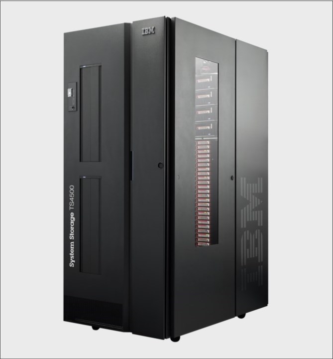
Figure 1-2 Base TS4500 tape library
TS4500 expansion frames can be wrapped with custom images, as shown in Figure 1-3.

Figure 1-3 TS4500s with image wrapped expansion frames
Eight types of frames are supported in the current TS4500 tape library range. Each frame is identified by a three-character model number (L25, D25, L55, D55, S25, S55, S24, and S54), which describes the nature of the frame.
The TS4500 tape library is built from a single frame model that is called the base frame. The scalability of the library allows an increase in capacity by adding up to 17 frames, which are called expansion frames. The frames join side by side and can grow to the left or right of the base frame. All frames can be supported by a dual cartridge single accessor, or by dual active accessors, with the HA feature installed. The TS4500 tape library can contain a mix of 3592 and LTO frames.
The TS4500 tape library supports first generation (S54 and S24) frames (HD1) and second-generation high-density (HD2) frames. HD2 frames, as with the first-generation HD1 frames, offer increased capacity without increasing the frame size or required floor space, by using high-density storage slots for tape cartridges.
In addition, HD2 frames provide the following enhancements:
•HD2 frames can be installed in the leftmost position of the library (frame number 1).
•Drive-capable HD2 frames support up to 16 HD2-compatible tape drives (3588 F9C, F9S, S9C, F8C, F7C, F6C, F5C, 3592 EH7, EH8, 55E, 55F, 60E, 60F, and 60S) when positioned as frame number 2 or higher.
Generation 1 HD frames from the TS3500 (Model S24 and S54) can be redeployed into a TS4500. These HD1 frames must be installed to the right of the Lx5 frame and require FC 1742 to be ordered for each S24 or S54 (Sx4) frames before they can exist in a TS4500 library string.
The L25 and L55 (Lx5) frames and D25 and D55 (Dx5) frames are HD2, drive-capable frames, which means that they contain high-density cartridge storage slots, and slots to house up to 16 tape drives. The S25, S55 (Sx5) HD2 frames and the S54, S24 (Sx4) HD1 frames are storage-only frames, which means that they contain high-density cartridge storage slots, but no tape drives. All HD frames provide internal light-emitting diode (LED) lighting.
The TS4500 also supports adding a top rack frame. The top rack, 3584 Model TR1, provides an extra 10U of rack space and 3584 Model TR2 provides an extra 5U of rack space on any frame in a library without requiring more floor space.
The frames that are supported by the library and their specific media type and capacity are listed in Table 1-2.
Table 1-2 TS4500 tape library frame models
|
Frame model
|
Type
|
Media type
|
Capacity
|
Other
| |
|
Frame position 1
|
Frame position 2+
| ||||
|
L25
|
Base frame
|
3592
|
Up to 12 tape drives and 552 storage slots
|
Up to 16 tape drives and 660 storage slots
|
•Equipped with two I/O stations and two 16-slot magazines
•Optionally equipped with top rack (Model TR1 or TR2)
|
|
L55
|
Base frame
|
LTO
|
Up to 12 tape drives and 732 storage slots
|
Up to 16 tape drives and 882 storage slots
|
•Equipped with two I/O stations and two 18-slot magazines
•Optionally equipped with top rack (Model TR1 or TR2)
|
|
D25
|
Expansion frame
|
3592
|
Up to 12 tape drives and 592 storage slots
|
Up to 16 tape drives and 740 storage slots
|
•Optionally quipped with two I/O stations and two 16-slot magazines
•Optionally equipped with top rack (Model TR1 or TR2)
|
|
D55
|
Expansion frame
|
LTO
|
Up to 12 tape drives and 776 storage slots
|
Up to 16 tape drives and 970 storage slots
|
•Optionally equipped with two I/O stations and two 18-slot magazines
•Optionally equipped with top rack (Model TR1 or TR2)
|
|
S25
|
Storage-only expansion frame
|
3592
|
800 storage slots
|
1,000 storage slots
|
Optionally equipped with top rack (Model TR1 or TR2)
|
|
S55
|
Storage-only expansion frame
|
LTO
|
1,056 storage slots
|
1,320 storage slots
|
Optionally equipped with top rack (Model TR1 or TR2)
|
|
S24
|
Storage-only expansion frame
|
3592
|
Not supported
|
1,000 storage slots
|
Optionally equipped with top rack (Model TR1 or TR2)
|
|
S54
|
Storage-only expansion frame
|
LTO
|
Not supported
|
1,320 storage slots
|
Optionally equipped with top rack (Model TR1 or TR2)
|
Capacity-on-Demand
In the TS4500 tape library, the physical capacity (or total storage slots) is composed of licensed and unlicensed capacity. When the number of assigned cartridges reaches the licensed capacity, more cartridges cannot be assigned to a logical library until a cartridge is removed, a CoD feature is purchased, or frames are added to the library.
The Intermediate, Base, and High-Density Capacity-on-Demand features provide license keys so that you can enable more storage slots in the frames of the TS4500 tape library.
Intermediate and base capacity on demand
Use the Intermediate and Base Capacity on Demand (CoD) features to increase the initial (entry) capacity of the base frames (models L25 and L55) of the TS4500 tape library.
Use the Intermediate and Base Capacity on Demand (CoD) features to increase the initial (entry) capacity of the base frames (models L25 and L55) of the TS4500 tape library.
The initial (entry) capacity of the L25 and L55 frames is 100 storage slots. You can purchase CoD features to increase the amount of available licensed capacity.
The Intermediate CoD feature (FC 1643) adds 100 slots, which increases the usable capacity of the L25 and L55 frames to 200 slots. The Base CoD feature (FC 1644) adds 200 slots, which increases the usable capacity of the L25 and L55 frames to 400 slots. FC 1644 is referred to as Full CoD with the TS4500 tape library.
High-Density capacity on demand
Use the High Density (HD) Capacity on Demand (CoD) license key to enable the full high-density capacity of the Lx5, Dx5, and Sx5 frames in the TS4500 tape library. Enabling the CoD on the TS4500 is a non-disruptive process.
Use the High Density (HD) Capacity on Demand (CoD) license key to enable the full high-density capacity of the Lx5, Dx5, and Sx5 frames in the TS4500 tape library. Enabling the CoD on the TS4500 is a non-disruptive process.
The initial (entry) capacity of the Lx5 frames is 100 slots. The Intermediate and Base CoD features can increase the usable capacity up to 400 slots. The HD CoD features add 150 to more than 450 slots, depending on frame position and configuration. The Base CoD feature (FC 1644) is a prerequisite for installing an HD CoD feature on an Lx5 frame.
The initial (entry) capacity of the Dx5 frames is 500 slots. The initial (entry) capacity of the S25 frame is 600 slots and the S55 frame is 660 slots. The HD CoD features can add 50 - 660 slots, depending on frame position and configuration.
The potential capacity by frame model is listed in Table 1-3.
Table 1-3 Potential capacity by frame model
|
Frame Model
|
Licensed feature
|
F1 slots available
|
F2+ slots available
|
|
L25
|
Entry
|
100
|
100
|
|
Intermediate
|
200
|
200
| |
|
Base
|
400
|
400
| |
|
HD CoD
|
552
|
660
| |
|
L55
|
Entry
|
100
|
100
|
|
Intermediate
|
200
|
200
| |
|
Base
|
400
|
400
| |
|
HD CoD
|
732
|
882
| |
|
D25
|
Base
|
500
|
500
|
|
HD CoD
|
592
|
740
| |
|
D25 with IO
|
Base
|
500
|
500
|
|
HD CoD
|
552
|
660
| |
|
D55
|
Base
|
500
|
500
|
|
HD CoD
|
776
|
970
| |
|
D55 with IO
|
Base
|
500
|
500
|
|
HD CoD
|
732
|
882
| |
|
S25
|
Base
|
600
|
600
|
|
HD CoD
|
800
|
1000
| |
|
S55
|
Base
|
660
|
660
|
|
HD CoD
|
1056
|
1320
| |
|
S24
|
Base
|
NA
|
600
|
|
HD CoD
|
NA
|
1000
| |
|
S54
|
Base
|
NA
|
660
|
|
HD CoD
|
NA
|
1320
|
1.2.1 TS4500 tape library frames for IBM LTO Ultrium Fibre Channel drives
The TS4500 tape library models L55 and D55 integrate the HD2 versions of the LTO-9, LTO-8, LTO-7, LTO-6, and LTO-5 tape drives. The TS4500 models S55 and S54 are high capacity storage-only frames for LTO cartridge slots.
The Model L55 frame includes the frame control assembly with two power supplies (for redundancy), an optimized dual-gripper cartridge accessor, on-demand storage slot capacity, and two I/O stations with two 18-slot magazines.
TS4500 tape library Model L55
The L55 frame can be installed on its own as a complete library enclosure (as shown in Figure 1-4) or up to 17 expansion frames can attach to it. This frame provides the major library components for the entire library, whether it has a single frame or multiple frames. It also provides cartridge storage capacity for LTO media, and can be equipped with the HD2 versions of the LTO-9, 8, 7, 6, and 5 dual-ported drives that facilitate 8 Gbps Fibre Channel connectivity.
HD2 expansion frames can be added to the left or right of the L55 frame. HD1 frames can be added only to the right side of L55 frame (see Figure 1-4).

Figure 1-4 TS4500 tape library L55/L25 base frame
The number of LTO cartridge storage slots ranges 100 - 882. With the minimum configuration, 100 slots are available for use. The maximum of 882 slots is physically installed and accessed by adding CoD license keys.
Many CoD feature codes exist for the L55 frame. The number of available slots depends on the frame position.
The Intermediate Capacity feature (FC 1643) gives a maximum total number of usable cartridge slots of 200. This feature is a prerequisite for the Base Capacity on Demand (FC 1644), which gives the maximum capacity of 400 cartridge slots. FC 1644 is required to attach an optional expansion frame. Both FC 1643 and FC 1644 are prerequisites to install the HD CoD for L55 (FC 1648), which gives the maximum capacity of 730 - 882 slots.
Depending on the frame position, a maximum of 16 LTO drives can be installed. Five generations of HD2-compatible LTO drives exist: the LTO Ultrium 9 tape drive (Model 3588 F9C, F9S, S9C), the LTO Ultrium 8 tape drive (Model 3588 F8C), LTO Ultrium 7 tape drive (Model 3588 F7C), LTO Ultrium 6 tape drive (Model 3588 F6C), and the LTO Ultrium 5 tape drive (Model 3588 F5C), which can be installed in the L55 frame. Drive slots are fixed. Adding drives to the L55 frame does not affect the number of available storage slots.
Figure 1-5 shows the drive slots and HD slots.

Figure 1-5 L55/L25 frame internal
When CoD features are installed, the position and configuration of the frame affect the total available capacity of the L55. The available storage capacity, which is based on the frame positions and configurations and capacity for each Tier, is listed in Table 1-4.
Table 1-4 Quantity of storage slots in the L55 frame
|
Licensed feature
|
F1 slots available
|
F2+ slots available
|
|
Entry
|
100
|
100
|
|
Intermediate
|
200
|
200
|
|
Base
|
400
|
400
|
|
HD CoD
|
732
|
882
|
The L55 frame included two I/O stations as standard. Each I/O station houses a cartridge magazine that allows individual cartridge handling to be performed independently of the tape library. The cartridge magazine for each I/O station on LTO frames can hold up to 18 cartridges, which provides a total of 36 I/O slots.
The TS4500 tape library Model L55 imports or exports cartridges from the library, without requiring reinventory or interruption of library operations. The lockable library door can be opened for bulk-loading LTO tape cartridges. Reinventory of the cartridges in tier 0 and tier 1 is performed in less than 60 seconds per frame, each time that the library door is closed. A bar code reader that is mounted on the autochanger is used to scan the cartridge bar code labels during inventory.
|
Important: If a bulk load is performed, the top two rows on tier 1 (drive side wall) must remain empty to allow for the initial inventory. Place only the cartridges in the frame that has the front door open. Do not insert cartridges into slots in an adjacent frame.
|
On an HD frame after initial inventory, the inventory checks tier 1 bar code labels only. It checks the other tier labels only if tier 1 changed.
A door lock is included to restrict physical access to the cartridges in the library. A door open sensor is equipped to prevent accessor movement while the door is open.
|
Note: The left and right side doors also contain the door lock and open sensor.
|
Included in the L55 frame is the IMC, which is a built-in platform for tools that are used to manage the TS4500 tape library. The IMC, which includes an LCD panel and a keyboard with a touchpad or track point, can be mounted on either end of your TS4500 tape library.
For more information about the IMC and other components, see 4.1, “Integrated management console” on page 186.
TS4500 tape library Model D55
The D55 frame, as shown in Figure 1-6, features the same footprint as the Model L55.

Figure 1-6 TS4500 model D55/L55
The D55 frame cannot be installed on its own. It must be connected to a library with a base frame. A maximum of 18 frames, including the L55 frame, can be connected, as shown in Figure 1-3 on page 7.
|
Note: The combined number of D55 or D25 drive frames that can be installed in a TS4500 library is limited to seven.
|
The number of extra LTO cartridge storage slots per D55 frame ranges is 500 - 970. With the minimum configuration, only 500 slots are available for use. More slots can be enabled by installing a capacity on demand (CoD) license key.
The base capacity on a D55 frame gives the maximum capacity of 500 cartridge slots.
FC 1644 must be installed on the L55 frame with FC 9002 or FC 9003, and the corresponding prerequisite feature code, to attach a D55 expansion frame, as described in 1.4, “Feature codes for the TS4500” on page 57. The HD CoD for D55 (FC 1650) gives the maximum capacity of 730 - 970 slots, depending on the frame position.
FC 1644 must be installed on the L55 frame with FC 9002 or FC 9003, and the corresponding prerequisite feature code, to attach a D55 expansion frame, as described in 1.4, “Feature codes for the TS4500” on page 57. The HD CoD for D55 (FC 1650) gives the maximum capacity of 730 - 970 slots, depending on the frame position.
Depending on the frame position, the maximum number of LTO drives that can be installed is 16. As with the L55 frame, the following generations of HD2-compatible LTO drives can be installed in the D55 frame:
•The LTO Ultrium 9 tape drive (Model 3588 F9C, F9S and S9C)
•The LTO Ultrium 8 tape drive (Model 3588 F8C)
•The LTO Ultrium 7 tape drive (Model 3588 F7C)
•The LTO Ultrium 6 tape drive (Model 3588 F6C)
•The LTO Ultrium 5 tape drive (Model 3588 F5C)
Drive slots are fixed. Adding drives to the D55 frame does not affect the number of available storage slots.
Figure 1-6 on page 14 shows the D55 frame with drive and HD slots.
Two extra I/O stations can be installed in any Dx5 expansion frame by ordering FC 1652. This feature installs two I/O stations in a drive expansion frame. Each extra pair of I/O stations increases the maximum insert/eject throughput for the library. The maximum cartridge capacity for expansion frames with two I/O stations is reduced by 88 cartridges for the Model D55.
The position and configuration of the frame, the number of I/O slots, and the installation of capacity on demand (CoD) features all affect the total available storage capacity of the D55.
The available storage capacity, which is based on possible frame positions and configurations and capacity for each Tier, is listed in Table 1-5.
Table 1-5 Quantity of storage slots in the D55 frame
|
Special frame considerations
|
Licensed feature
|
F1 slots available
|
F2+ slots available
|
|
D55 with no IOs
|
Base
|
500
|
500
|
|
D55 with no IOs
|
HD CoD
|
776
|
970
|
|
D55 with IOs
|
Base
|
500
|
500
|
|
D55 with IOs
|
HD CoD
|
732
|
882
|
1.2.2 TS4500 tape library frames for IBM 3592 drives
The TS4500 tape library models L25 and D25 integrate the TS1160, TS1155, TS1150, and TS1140 tape drives. The TS4500 Model S25 is a high-capacity, storage-only frame for 3592 slots.
The Model L25 frame includes the Frame Control Assembly (FCA) with two power supplies (for redundancy), an optimized dual-gripper cartridge accessor, on-demand storage slot capacity, and two I/O stations with two 16-slot magazines.
TS4500 tape library Model L25
The L25 can be installed on its own as a complete library enclosure (as shown in Figure 1-4 on page 11) or it can have up to 17 expansion frames that are attached to it. This frame provides the major library components for the whole library, whether it has single or multiple frames. It also provides cartridge storage capacity for 3592 media and can be equipped with TS1160 (3592 model 60F) facilitating dual-ported 16 Gbps Fibre Channel connectivity, or TS1155, TS1150, and TS1140 (3592 models 55F, EH8, and EH7), which facilitates dual-ported 8 Gbps Fibre Channel connectivity.
The TS1160 (3592 model 60E) provides dual 10 or 25 Gb Ethernet host attachment interface. The TS1155 (3592 model 55E) provides dual 10 Gb Ethernet host attachment interface, which is optimized for cloud-based and large, open-compute environments.
The TS1160 (3592 model 60S) provides a dual-port 12 Gb SAS (Serial Attached SCSI) interface for host attachment. This drive brings more versatility to businesses with substantial storage, backup, and archiving demands with a cost-competitive communications interface to help simplify storage management and system performance.
The HD2 expansion frame can be added to the left or right of the L25 frame. HD1 frames can be added only to the right side of the L25 frame.
The Intermediate Capacity feature (FC 1643) gives a maximum of 200 usable cartridge slots. This feature is a prerequisite for the Base Capacity on Demand feature
(FC 1644), which gives the maximum capacity of 400 cartridge slots. FC 1644 is required to attach an optional expansion frame. FC 1644 is a prerequisite to install the HD CoD for L25 (FC 1647), which offers the maximum capacity of 550 - 660 slots.
(FC 1644), which gives the maximum capacity of 400 cartridge slots. FC 1644 is required to attach an optional expansion frame. FC 1644 is a prerequisite to install the HD CoD for L25 (FC 1647), which offers the maximum capacity of 550 - 660 slots.
Depending on the frame positions, a maximum of 16 3592 drives can be installed. Four generations of HD2-compatible 3592 drives, the TS1160 (3592 60E, 60F, and 60S), TS1155 (3592 55F and 55E), TS1150 (3592 E08), and TS1140 (3592 E07) tape drives, are supported in the L25 frame. Drive slots are fixed. Adding drives to the L25 frame does not affect the number of available storage slots.
Figure 1-7 shows an L25 frame drive and HD slots.

Figure 1-7 TS4500 model D25/L25
The position and configuration of the frame and the installation of CoD features affect the total available capacity of the L25. The available storage capacity, which is based on possible frame positions and configurations and capacity for each Tier, is listed in Table 1-6 on page 17.
Table 1-6 Quantity of storage slots in the L25 frame
|
Licensed feature
|
F1 slots available
|
F2+ slots available
|
|
Entry
|
100
|
100
|
|
Intermediate
|
200
|
200
|
|
Base
|
400
|
400
|
|
HD CoD
|
552
|
660
|
The L25 frame includes two I/O stations as standard. Each I/O station houses a cartridge magazine that allows importing or exporting cartridges from the library without requiring reinventory or an interruption of library operations. The cartridge magazine for each I/O station on 3592 frames can hold up to 16 cartridges, which provides a total of 32 I/O slots.
The lockable library door can be opened for bulk-loading IBM LTO Ultrium tape cartridges. Reinventory of the cartridges in tier 0 and tier 1 is performed in less than 60 seconds per frame each time that the library door is closed. A bar code reader that is mounted on the gripper is used to scan the cartridge bar code labels during inventory.
|
Important: If a bulk load is performed, the top two rows on tier 1 (drive side wall) must remain empty to allow for the initial inventory.
|
On an HD frame, the inventory checks tier 0 and tier 1 bar code labels only, and the inventory checks the other tier labels only if tier 1 changed.
A door lock is included to restrict physical access to cartridges in the library. A door open sensor also is equipped to prevent accessor movement while the door is open.
Included in the L25 frame is the IMC, which is a built-in platform for tools that are used to manage the TS4500 tape library. The IMC, which includes an LCD panel and a keyboard with a touchpad, can be mounted on either end of your TS4500 tape library. For more information about the IMC and other components, see Chapter 4, “TS4500 management graphical user interface” on page 185.
TS4500 tape library Model D25
The D25 frame, as shown in Figure 1-6 on page 14, features the same footprint as the Model L25. The D25 frame cannot be installed on its own. It must be connected to a library with a base frame. A maximum of 18 frames, including the L25 frame, can be connected, as shown in Figure 1-3 on page 7.
|
Important: The combined number of allowed D55 or D25 frames in a TS4500 library is limited to seven.
|
The number of extra 3592 cartridge storage slots per D25 frame is 500 - 740. With the minimum configuration, only 500 slots are available for use.
More slots can be enabled by installing a CoD license key.
The base capacity on a D25 frame gives the maximum capacity of 500 cartridge slots.
FC 1644 must be installed on the L55 frame with FC 9002 or FC 9003 and the corresponding prerequisite FC to attach a D25 expansion frame, as described in 1.4, “Feature codes for the TS4500” on page 57.
FC 1644 must be installed on the L55 frame with FC 9002 or FC 9003 and the corresponding prerequisite FC to attach a D25 expansion frame, as described in 1.4, “Feature codes for the TS4500” on page 57.
The HD CoD for D25 (FC 1649) gives the maximum capacity of 660 - 740 slots, depending on the frame position.
Depending on the frame position, a maximum of 16 3592 drives that can be installed. The following drives are supported in the D25 frame:
•Four generations of HD2-compatible 3592 drives
•TS1160 (3592 60E, 60F, and 60S)
•TS1155 (3592 55E and 55F)
•TS1150 (3592 E08)
•TS1140 (3592 E07)
Drive slots are fixed. Adding drives to the D25 frame does not affect the number of available storage slots.
Figure 1-7 on page 16 shows the drive slots and HD slots.
Two extra I/O stations can be installed in any Dx5 expansion frame by ordering FC 1652. This feature installs two I/O stations in one expansion frame. Each extra pair of I/O stations increases the maximum insert/eject throughput for the library. The maximum cartridge capacity for expansion frames with two I/O stations is reduced by 80 cartridges for the Model D25 frame.
The position and configuration of the frame, the number of I/O slots, and the installation of CoD features all affect the total available storage capacity of the D55. The available storage capacity, based on possible frame positions and configurations and capacity for each Tier, is listed in Table 1-7.
Table 1-7 Quantity of storage slots in the D25 frame
|
Special frame considerations
|
Licensed feature
|
F1 slots available
|
F2+ slots available
|
|
D25 with no IOs
|
Base
|
500
|
500
|
|
D25 with no IOs
|
HD CoD
|
592
|
740
|
|
D25 with IOs
|
Base
|
500
|
500
|
|
D25 with IOs
|
HD CoD
|
552
|
660
|
1.2.3 TS4500 tape library storage-only HD frames
In this section, we describe the storage-only HD frames that are offered by the TS4500 tape library.
Model S55 and S25
The IBM TS4500 includes the Model S25 frame and the Model S55 frame, which are high density (HD) version 2 storage-only expansion frames, as shown in Figure 1-8.
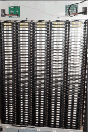
Figure 1-8 Sx5/Sx4 frame
These frames are designed to increase storage capacity greatly without increasing the frame size or required floor space.
The HD slots contain tape cartridges in a tiered architecture. The cartridge, which is immediately accessible in the HD slot, is a tier 1 cartridge (behind that tier is tier 2, and so on).
The maximum tier in an LTO HD slot is tier 5. The maximum tier in a 3592 HD slot is tier 4 because the 3592 tape cartridge is slightly longer than the LTO cartridge. The single-deep slots on the door side of HD frames are referred to as tier 0 slots.
A side view of the inside of an HD frame is shown on the left side of Figure 1-9. A top-down view of one row of an HD frame with cartridges in tier 0 (door side), 1 (Drive side), 2, 3, 4, and 5 is shown on the right side of Figure 1-9. Tier 5 is for LTO frames only.

Figure 1-9 The HD frame (left) and top-down view of a row in an HD frame (right)
Models S24 and S54
The IBM TS3500 storage-only frame, HD1 models S24 and S54, can be attached to the TS4500 with the correct FC 1742 ordered.
These generation 1 HD frames can be redeployed into a TS4500 if they are installed to the right of the Lx5 frame. You must install FC 1742 before the frames can be added to a TS4500 library string. This feature code replaces the TS3500 cards to be supported on the TS4500, as shown in Figure 1-10.

Figure 1-10 Changes to S24/S54 for TS4500 attachment
The TS3500 tape library models S24 and S54 frames are high-density (HD) version 1 storage-only expansion frames, which were attached to TS3500 tape libraries and frames.
The Model S24 expansion frame is for 3592 data cartridges. Up to 17 Model S24 expansion frames can be added to the right of the Lx5 frame of the TS4500 Model L25 base frame to increase 3592 cartridge storage. Each Model S24 frame supports up to 1,000 IBM 3592 cartridge slots.
The Model S54 expansion frame is for LTO data cartridges. Up to 17 Model S54 expansion frames can be added to the right of the Lx5 frame of the TS4500 tape library Model L55 base frame to increase LTO cartridge storage. Each Model S54 frame supports up to 1,320 LTO cartridge slots.
The HD1 models S24 and S54 can be added to any TS4500 expansion frame, if the expansion frame is added to the right of the Lx5 frame, up to a total of 18 expansion frames, including the Lx5 frame.
|
Note: The HD1 models S24 and S54 cannot be installed to the left of the Lx5 frame and cannot be installed as the rightmost frame in a dual accessor tape library.
|
HD1 and HD2 frames
All HD slots are black. However, the location of the cartridge retention latch differentiates LTO HD slots from 3592 HD slots. The cartridge retention latch is on the left side of LTO HD slots and on the right side of 3592 HD slots, as shown in Figure 1-11.
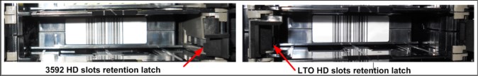
Figure 1-11 HD slot
|
Attention: The HD slots use a constant force spring to maintain forward pressure on the tape cartridges. Use caution when you insert or remove cartridges from the HD slots.
|
In an HD library, a standard inventory is a scan of tier 0 and tier 1. However, at times, it is necessary to inventory all tier. This operation takes more time because it requires moving the cartridges within an HD slot to scan each bar code. For all inventory operations, tier 2, and higher tier in an HD slot, are scanned only when one of the following changes occurs:
•A tier 1 cartridge bar code label was changed.
•Enough tier 1 bar code labels were changed in a column to warrant an inventory of the entire column of HD slots.
•Inventory of all tier is selected when you start a manual inventory from the TS4500 management GUI.
In HD frames, the cartridge accessor performs a shuffle operation to access the cartridges that are stored in tier 2 and higher. A shuffle is the process of moving cartridges in lower tier into the gripper, or other available slots, to access cartridges in higher tier (tier 2 or higher). To reduce shuffle operations and take advantage of repeated accesses of certain cartridges, the role of cartridge cache is assigned to all single-deep (tier 0) slots in an HD library.
To maintain efficient shuffle operations, the library uses load balancing to store cartridges across all HD slots in the library string. Therefore, all HD slots are filled to a minimum tier level until that tier is full across the library.
For the initial bulk load on a newly installed frame, insert cartridges into the deep slots, but leave the top two rows empty. The slots in the top two rows must be empty for the initial audit of the frame to start, and to enable the initial shuffle operation to proceed. The initial audit fills these slots, and then these slots are used like any other HD slot in subsequent library operations.
First-generation HD (HD1) frames can be installed to the right side of an Lx5 frame only.
Second-generation HD (HD2) frames provide the following enhancements:
•They can be installed in the leftmost library position (frame position 1).
•They offer drive-capable models that support up to 16 HD2-compatible tape drives when in frame position 2 or higher.
The position and configuration of the frame and the installation of CoD features affect the total available storage capacity of the S25 and S55 frames.
The available storage capacity based on possible frame model, position and configurations is listed in Table 1-8.
Table 1-8 Quantity of storage slots in the storage-only frames
|
Frame model
|
Licensed feature
|
F1 slots available
|
F2+ slots available
|
|
S25
|
Base
|
600
|
600
|
|
S25
|
HD CoD
|
800
|
1000
|
|
S24
|
Base
|
NA
|
600
|
|
S24
|
HD CoD
|
NA
|
1000
|
|
S55
|
Base
|
660
|
660
|
|
S55
|
HD CoD
|
1056
|
1320
|
|
S54
|
Base
|
NA
|
660
|
|
S54
|
HD CoD
|
NA
|
1320
|
1.2.4 TS4500 High Availability option
The TS4500 High Availability (HA) option provides a second accessor for redundancy and performance. This feature allows dual accessors in a dual active mode, and it features an integrated service bay to reduce service space.
The integrated service bays replace the HA frame and Service Bay B frames that are used on the TS3500. The integrated service bays allows a section of a frame to be used for servicing an accessor while the remaining portion of the frame is still available for active storage and drives. Accessor service must be performed through the side by opening the side doors of integrated service bays. Any HD2 frame can be an integrated service bay.
The second accessor, accessor B, is provided when you order a new Dx5 or Sx5 frame with FC 1442. The new Dx5 or Sx5 frame can be installed in any position, and it is included with the new B accessor. The accessor can be removed from the new frame and installed on the right side of the TS4500 if the new frame is installed on the left side.
Figure 1-12 shows the HA feature that is included in a new D25 frame.

Figure 1-12 D25 frame that was ordered with FC 1442
|
Restriction: The left or A side-integrated service bay (ISB) allows cartridges to be populated in storage columns 9 and 10, while drives can be populated in drive column 4 only.
The right or B side ISB allows cartridges to be populated in storage columns 1, 2, 3, and 4, while drives can be populated in drive columns 1 and 2 only. The I/O stations are accessible in the right integrated service bay.
An integrated service bay allows a minimum dual accessor system of only two frames.
|
The available storage for HA is shown in Figure 1-13.

Figure 1-13 Available storage with an HA option
|
Note: I/O stations are not accessible in the left integrated service bay; therefore, an L25 or L55 frame cannot be used as a left integrated service bay. The frame that is included with the HA option can be installed on the left side (if required) because no dedicated service bays are on that side. The new accessor must be installed in the frame on the right side.
|
Elastic Capacity option
The TS4500 provides the Elastic Capacity option to completely eliminate inactive service space. The Elastic Capacity option can provide temporary relief for overflow conditions. These slots are referred to as tier T10 - T15 slots on LTO and T10-T14 on 3592. Standard storage slots are Tier 0 - 5 on LTO or Tier 0-4 on 3592.
With dual active accessors, certain storage slots are only available to a single accessor, and they are unavailable during accessor service. The ability to use these slots is optional, and they can be enabled or disabled on the management interface. The following modes are available for the Elastic Capacity option:
•Do not use
•Use for temporary overflow
•Use for maximum capacity
Do not use
In this mode, the TS4500 does not use the Elastic Capacity slots for media storage; therefore, all media is usable when only one accessor is available. Tier T10 - T15 slots are not used.
Use for temporary overflow
In this mode, cartridges are moved to elastic storage only if the library is 100% full, and if new inserts have no other destination choice. In this case, T10 and higher is used as temporary storage to handle the library overfill. Cartridges are returned to HA space after space becomes available manually by a user, or when the application mounts and unmounts the cartridges in the elastic capacity slots (T10 and higher).
Use for maximum capacity
Use this setting to store media cartridges in the limited access (Elastic Capacity) columns as normal storage. The use of these slots can be managed by using the following methods:
•Manually: A user can select a cartridge to destage to elastic storage by using the command-line interface (CLI). If the cartridge is already in elastic storage, no action is taken.
•Small Computer System Interface (SCSI): An application can use the HD Control field of the SCSI Move Medium command to specify that the move is an elastic storage destage.
•Periodic: When the dual-access area (the cartridge slots that both A and B accessors can reach) exceeds the usage threshold, the least recently used cartridges are moved into the Elastic Capacity area. The default usage threshold is 98%.
|
Note: “Use for maximum capacity” is the default setting if the setting is not changed.
|
TS4500 capacity tool
The IBM Tape Library Slot Calculator helps calculate capacity and slot numbers for all IBM tape libraries, including TS3100, TS3200, TS3310, TS3500, and the TS4500. This calculation includes capacity with the different elastic capacity options.
This tool is available at this IBM Support web page.
Slot calculation is much more complex than totaling the numbers of slots in each frame. The slot calculator provides the available slot capacity that is based on any configuration. Of particular note is the “Elastic (Non-HA) capacity” utilization, which shows elastic usage with the current configuration. The does not use the elastic capacity until the number of CoD features reach a specific threshold.
The following examples show the effect on slot capacity when adding the HA feature (dual accessors). The examples show that overall capacity is available globally to the library, even though the CoD license keys are purchased against individual frame serial numbers.
Figure 1-14 shows an example of a 6-frame single accessor configuration with 3950 licensed slots available.

Figure 1-14 6-frame configuration example: Single Accessor
Based on the same configuration, if we add the HA feature to make it a dual accessor library, we can see the effect that this addition has on slot numbers.
|
Note: Frame 6 now includes the service bay for the second accessor, which means that access to some columns and therefore storage slots are restricted. However, although the library is not fully licensed with CoD features, the firmware compensates for the loss of the slots that is caused by the second accessor installation.
|
In Figure 1-15, we can see that adding the dual accessor (HA) has no effect on the number of licensed storage slots, and that the elastic capacity is not used.

Figure 1-15 6-frame configuration example: Dual Accessor
1.2.5 Mainframe-ready
From FW release 3, the TS4500 is supported on IBM z/OS systems with an attached TS7700. The TS7700 requires FW release 4 and higher to attach to a TS4500.
To provide this support, the TS4500 must have two integrated 16 Gb Fibre Channel switches, which can be installed in the bottom of a L25 or D25 frame, as shown in Figure 1-16.

Figure 1-16 Integrated TS7700 back-end switches
If a migration of the 16 Gb Fibre Channel Switch is from a TS3500 TopRack (TR1) to be installed on a TS4500, the following options are available:
•TopRack can be reinstalled with the switches on the TS4500; the existing TS3500 TR1 can be moved to the TS4500 (see Figure 1-19 on page 30).
•Order only FC 4879 (TS7700 BE Switch Mounting Hardware), which provides the switch mounting kit without switches. This option is provided as a field MES if the TS4500 is already installed.
The TS4500 management GUI supports the preset TS7700 logical library and the use of an external TSSC/IMC.
|
Note: The integrated Fibre Channel switches do not require extra power feeds to the TS4500. The integrated Fibre Channel switches use bifurcated power cords that are provided with the mounting kit hardware for the switches. These power cords connect internally to the existing TS4500 Power Distribution Units.
|
1.2.6 External TSSC/IMC
The TS4500 supports the use of an external TSSC/IMC so that a single TSSC provides the Call Home capability for several TS7700, TS4500, or TS3500 devices on the same site, as shown in Figure 1-17.

Figure 1-17 External TSSC server
|
Note: The external TSSC can also be a TSSC/IMC inside another TS4500. This configuration requires that you install FC 2704 on the Lx5 frame. FC 2704 provides a 26-port switch to allow connection to up to 24 extra devices to share the TSSC/IMC.
Only one TSSC/IMC can be configured for IBM Call Home: the external TSSC/IMC or by using an internal IMC.
|
1.2.7 TS4500 tape library top rack frame TR1 and TR2
The TS4500 top racks provide extra rack space on any frame in a library without requiring more floor space. They also simplify cabling by providing extra rack space above the library for power distribution units, Fibre Channel switches, tape data movers, or IBM Linear Tape File System (LTFS) nodes.
Both Top Rack models (TR1 and TR2) are installed in the field by an IBM service representative or service partners on one or more frames. The top racks, and any components that are housed in the racks, are supported and serviced independently of the TS4500 tape library.
FC 1750, top rack end covers, is required for the left and right ends of one or more adjacent top racks. This feature is required for only the first top rack that is ordered when multiple top racks are ordered for adjacent frames.
3584 Model TR1
The optional top rack, 3584 Model TR1 (see Figure 1-18), provides an extra 10U of rack space on any frame. The components that are placed into the top rack should not exceed 30 lbs per U, which is a maximum of 300 lbs for the TR1.

Figure 1-18 Tape library with an installed top rack TR1
FC 1751 power distribution unit (PDU), or 1752 Enhanced PDU, optionally can be ordered. Up to two PDUs can be ordered for the TR1. The first PDU does not use any of the 10U rack space. A second PDU (for redundancy) uses 1U of rack space.
One power cord feature, 9954 - 9959 or 9966, is required for each 1751 feature that is ordered. One power cord feature, 9954 - 9958 or 9948, is required for each 1752 feature that is ordered.
3584 Model TR2
The TR2 provides an extra 5U of rack space on any frame. The lower overall size of Model TR2 compared to Model TR1 enables you to install TR2 where overhead space prevents TR1 from being installed. The components that are placed into the top rack should not exceed 30 lbs per U, which is a maximum of 150 lbs for the TR2. FCs 1755 (Front Door) and 1756 (Rear Door) are optional.
Rack configurations
The following rack configurations are available:
•Standard 19-inch Rack (FC 1754)
The TR2 is configured in conformance with industry standard 19-inch racks. This configuration provides 5U of 19-inch rack space.
•Olympus Rack (Feature code 1753)
The TR2 rack is configured in conformance with the Open Compute Project Olympus Rack Specification.
FC 1752, Enhanced PDU, optionally can be ordered for the TR2. Each PDU uses 1U of rack space. Up to two of FC 1752 can be ordered. Each Enhanced PDU provides six C13 outlets and three C19 outlets.
Power cords
Consider the following points:
•For single phase input power, each PDU order you must order one power cord FCs 9954 - 9958.
•For 3-phase (wye) input power, each PDU that you order must order one power cord FC 9948.
Figure 1-19 shows the top rack without covers and devices installed.

Figure 1-19 Top rack without covers and devices
|
Important: The top rack is treated as an independent rack space, and it is not tied to the service or support of the tape library.
|
1.3 TS4500 tape library components
The TS4500 tape library consists of one or more frames, which include more components that supply power to the library, installed tape drives, and components for handling and storing tape cartridges.
Each available component in the front and side of the frame is shown in Figure 1-20.
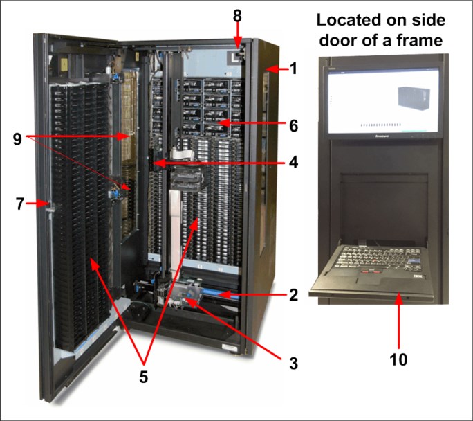
Figure 1-20 TS4500 components that are available from the front of the frame
The components that are shown in Figure 1-20 on page 31 are listed in Table 1-9.
Table 1-9 Inside the front of the TS4500
|
Number
|
Component
|
|
1
|
Library frames
|
|
2
|
Rail system
|
|
3
|
Cartridge accessor
|
|
4
|
Accessor controller
|
|
5
|
Cartridge storage slots
|
|
6
|
IBM LTO or 3592 tape drives
|
|
7
|
Front door
|
|
8
|
Door safety switch
|
|
9
|
I/O stations
|
|
10
|
Integrated management console
|
Accessor B is in the right-side frame. Accessor B is functionally the same as accessor A, as shown in Figure 1-21.

Figure 1-21 Dual accessor
The location of each component that is available in the top and rear of the frame is shown in Figure 1-22.

Figure 1-22 Top and rear of the TS4500
The components that are shown in Figure 1-22 are listed in Table 1-10.
Table 1-10 Top and rear components of the TS4500
|
Number
|
Component
|
|
11
|
Power cable hole
|
|
12
|
Fibre Channel cable hole
|
|
13
|
Frame control assembly
|
|
14
|
Patch panel
|
|
15
|
Rear of IBM LTO or 3592 tape drives
|
The location of each component that is available on the front door is shown in Figure 1-23.

Figure 1-23 Front door
The components that are shown in Figure 1-23 are listed in Table 1-11.
Table 1-11 Front door components of the TS4500
|
Number
|
Component
|
|
16
|
Display panel
|
|
17
|
I/O stations
|
Library frames
The base frame (Lx5 models) and the expansion frames (Dx5, Sx5, and Sx5 models) are the building blocks of the library. Each frame contains a rail system, high-density cartridge storage slots, and internal LED lighting. The Lx5 and Dx5 frames also contain slots for up to 16 tape drives.
Rail system and track cable
The cartridge accessor moves through the TS4500 tape library on a rail assembly. The system consists primarily of a main rail assembly and a support rail, and a trough for the power and control cable. The main rail assembly includes a main bearing way with a rack gear. Its support rail is an L-shaped rail that runs along the top of the frames and provides smooth transport for the cartridge accessor.
TS4500 has a newly designed flex track cable and guide. This new flex track cable and guide was designed to reduce cost and outage time when you add a frame (see Figure 1-24).

Figure 1-24 Rail system and track cable
The new style of cable requires no tools to install or replace. It is stacked in a new guide that is designed with two-chambers, which separate signal and power wires. Accessor A uses the top guide and accessor B uses the bottom guide, as shown in Figure 1-25.

Figure 1-25 Track cable guide
These cables plug into the same frame. Depending on the library size, chose the suitable cable length and install in the correct frame, as listed in Table 1-12.
Table 1-12 Flex track installation frames
|
Flex track cable size
|
Installations in frame
|
|
1 - 2 frames
|
1
|
|
3 - 6 frames
|
3
|
|
7 - 14 frames
|
7
|
|
9 - 18 frames
|
9
|
|
Important: When you add the new HA feature to a TS4500, you must order FC 2071 or FC 2072 for each frame in addition to ordering the correct length flex track cable.
|
Cartridge accessor
The cartridge accessor moves cartridges between the storage slots, tape drives, and the I/O station of the TS4500 tape library. If the HA option is installed, two accessors exist: accessor A and accessor B. Functionally, accessor A and accessor B are identical. They have the same hardware components, except for a bottom bumper and the location of the X home sensor moving to the right side of accessor B.
The accessors consist of the components that are described next.
X-axis and Y-axis motion assemblies
This group of parts includes a controller (circuit board) for the Controller Area Network interface, servo motor, pinion drive gear, and lead screw. These assemblies provide the motive force to move the accessor side to side (on the X-axis) and up and down (on the Y-axis). The controller part of this assembly is referred to as the XY controller, as shown in Figure 1-26.

Figure 1-26 Motion assembly
Pivot assembly
This group of parts provides a mounting platform for the gripper mechanism and the bar code reader. This assembly can rotate 180° around the vertical axis, as shown in Figure 1-27.
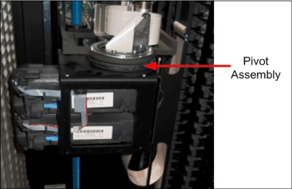
Figure 1-27 Pivot assembly
Optimized dual gripper
This electromechanical device (which is mounted on the pivot assembly) gets or puts cartridges from or to a storage slot, tape drive, or I/O station. The gripper is independently controlled, and it can grip a single cartridge. Two grippers are on the pivot assembly (Gripper 1 and Gripper 2). The grippers are in the dual-gripper transport mechanism, as shown in Figure 1-28.

Figure 1-28 Dual gripper
Bar code reader and calibration assembly
This assembly has a dual purpose: It reads the bar code on a label that is affixed to a cartridge or to the rear of empty storage slots, and calibrates the frame after the installation or hardware change. The bar code reader/calibration sensor is mounted on the bottom of the top gripper, and it can be seen between the two grippers when viewed from the front. It is used for frame calibration during inventories, audits, insertions, and inventory updates (a process that is invoked each time that you open a door).
An Auxiliary Lighting Element (ALE) assists the bar code reader. The ALE provides light to assist the bar code reader to scan labels correctly. The ALE connects to the top of the bottom gripper.
The inventory update determines whether cartridges are added to or removed from the library, or moved within the library. The bar code assembly, calibration assembly reader, and ALE are shown in Figure 1-29.

Figure 1-29 Bar code reader, calibration sensor, and ALE
Accessor controller
This controller is a circuit board that facilitates all accessor motion requests, such as calibrations, moves, and inventory updates. This controller is on the side of the accessor assembly, as shown in Figure 1-30.

Figure 1-30 Accessor controller
Cartridge storage slots
All frames contain single-deep cells that are mounted on the door of the frame. Each cell stores one tape cartridge. High-density cells are mounted on the inside wall of each frame. These high-density cells each store four (3592) or five (LTO) tape cartridges. Individual frames do not support mixed media (a combination of 3592 and LTO tape cartridges). However, mixed media is supported within the TS4500 tape library.
Release 2 introduces new single-deep cells for both LTO and 3592 cartridges that are on the door side of HD2 frames. A chevron fiducial, which is similar to the chevron fiducial that is on the deep cells for individual cell calibration, is included in the new single-deep cells. Ribs are included to reduce cell wear, and they are a new feature of the single-deep cells, as shown in Figure 1-31.

Figure 1-31 New door side single-deep cell slots
IBM LTO or 3592 tape drives
Drive frames can contain one or more units that are mounted in the frame. The TS4500 tape library supports LTO and 3592 tape drives. The HD2 frames of the TS4500 tape library support HD2-compatible models of the TS1160, TS1155, TS1150, TS1140, LTO-9, 8, 7, 6, and 5 tape drives.
Up to 12 drives can be installed in an Lx5 or Dx5 frame that is in frame position 1 (the leftmost frame) of the library. Up to 16 drives can be installed in each Lx5 or Dx5 frame that is in frame position 2 or higher. Within a HA configuration, the maximum number of drives that can be installed in the first frame is four and in the last frame is eight, if the frame is a Lx5 or Dx5 frame.
LTO and 3592 tape drives cannot be mixed in the same frame, but the LTO and 3592 frames can be mixed in the same library. You can identify a drive by inspecting the label at the rear of the drive canister. For more information about these drives, see Chapter 2, “TS4500 Ultrium Linear Tape-Open and 3592 tape drives” on page 77.
|
Note: No drives are installed in the storage-only frames (models S25, S24, S55, and S54).
|
The supported tape drives are listed in Table 1-13.
Table 1-13 Tape drives that are supported by the TS4500 tape library
|
Type of drive
|
Speed of connection
|
Native data rate
|
Native capacity
read/write
|
Other information
|
|
IBM LTO Ultrium 9
|
8 Gbps Fibre for model F9C and F9S
12 Gbps SAS for model S9C
|
400 MBps
|
18 TB
(16.37 TiB)
|
Known as the LTO-9 tape drive, Model 3588 F9C, F9S and S9C, TS1090
|
|
IBM LTO Ultrium 8
|
8 Gbps Fibre
|
360 MBps
|
12 TB
(10.91 TiB)
|
Known as the LTO-8 tape drive, Model 3588 F8C, TS1080
|
|
IBM LTO Ultrium 7
|
8 Gbps Fibre
|
300 MBps
|
6 TB
(5.46 TiB)
|
Known as the LTO-7 tape drive, Model 3588 F7C, TS1070
|
|
IBM LTO Ultrium 6
|
8 Gbps Fibre
|
160 MBps
|
2.5 TB
(2.27 TiB)
|
Known as the LTO-6 tape drive, Model 3588 F6C, TS1060
|
|
IBM LTO Ultrium 5
|
8 Gbps Fibre
|
140 MBps
|
1.5 TB
(1.36 TiB)
|
Known as the LTO-5 tape drive, Model 3588 F5C, TS1050
|
|
IBM TS1160
|
16 Gbps Fibre for model 60F
10 or 25 Gbps Optical Ethernet for model 60E
12 Gbps SAS for model 60S
|
400 MBps
|
•900 GB (.82 TiB)
with JK •5 TB
(3.63 TiB) with JM •7 TB
(6.37 TiB) with JC/JY •15 TB
(13.64 TiB) with JD/JZ •20 TB
(18.19 TiB) with JE/JV |
Known as the 3592 60E, 3592 60F, or 3592 60S tape drive
|
|
IBM TS1155
|
8 Gbps Fibre
for model 55F
10 Gbps Optical Ethernet for model 55E
|
360 MBps
|
•900 GB
(.82 TiB) with JK •3 TB
(2.73 TiB) with JL •7 TB
(6.37 TiB) with JC/JY •15 TB
(13.64 TiB) with JD/JZ |
Known as the 3592 55E or 3592 55F tape drive
|
|
IBM TS1150
|
8 Gbps Fibre
|
360 MBps
|
•900 GB
(.82 TiB) with JK •2 TB
(1.82 TiB) with JL •7 TB
(6.37 TiB) with JC/JY •10 TB
(9.1 TiB) with JD/JZ c |
Known as the 3592 EH8 tape drive
|
|
IBM TS1140
|
8 Gbps Fibre
|
250 MBps
|
•500 GB
(.48 TiB) with JK •1.6 TB
(1.46 TiB) with JB/JX •4 TB (3.6 TiB)
with JC/JY |
Known as the 3592 EH7 tape drive
|
Figure 1-32 shows the TS4500 drive bay.

Figure 1-32 TS4500 drive bay
Front door
The front door contains single cartridge storage slots on the inside of the door that are referred to as tier 0 slots. Two I/O stations are installed on the front door of the base frame. Optionally, two extra I/O stations can be installed on the front door of any Dx5 frame. The library’s front door has a key lock. The key lock is the same for every front door, and the keys are included with the library. The front door is shown in Figure 1-23 on page 34.
|
Note: The side doors of the base frames (Lx5) also have a key lock, which is the same key lock that is used for the front door.
|
Door safety switch
This switch ensures that power to the cartridge accessor is switched off whenever the front door or side door is opened. This safety component ensures that accessor movement is stopped while the front door is open. Figure 1-33 shows the front door safety switch.

Figure 1-33 Front door safety switch
Side door and accessor service access
To service a single accessor concurrently, the accessor that requires service must be placed into service mode from the management GUI. After the accessor parks, and the side door is open, the service bay switch (SBS) activates. This sequence puts the SBS into the up position. Figure 1-34 shows the SBS mechanism.

Figure 1-34 Service bay switch mechanism
Figure 1-35 shows an accessor in service with side door open and end stop up. The second accessor is working and it is prevented from moving into the service area by the end stop.

Figure 1-35 Accessor in service
To service the accessor, it must be removed from the TS4500 by using the side door. This action is a concurrent action with the second accessor that is used for move commands. This process is simple because the end stops and track cable can be removed without any tools.
I/O stations
Two I/O stations on the front door of the base frame enable the insertion or removal of tape cartridges without requiring the library to reinventory the frame. Optionally, two more I/O stations can be installed on any Dx5 expansion frame. The I/O station is universal, and either LTO or 3592 magazines can be installed in it.
Cartridges can be inserted or removed by using the I/O stations while the TS4500 tape library performs other operations without requiring an inventory.
The TS4500 tape library base frames (models L25 and L55) come with two I/O stations. Each I/O station houses a cartridge magazine so that individual cartridges can be handled independently of the tape library. Consider the following points:
•A cartridge magazine for LTO can hold up to 18 cartridges.
•A cartridge magazine for 3592 can hold up to 16 cartridges.
On libraries with LTO and 3592 frames, the first Dx5 frame (different from the Lx5) can have I/O stations that are included with magazines for the different drive type. The LTO and 3592 magazines can be installed on any I/O station.
Magazines for different media types can also be ordered by using FC 1628 for LTO and
FC 1629 for 3592.
FC 1629 for 3592.
The handles on the cartridge magazine are used to insert and remove the magazine, or to carry it during transport. The magazine safety lock, as shown in Figure 1-36, retains cartridges in their slots and prevents them from falling out while the magazine is transported.
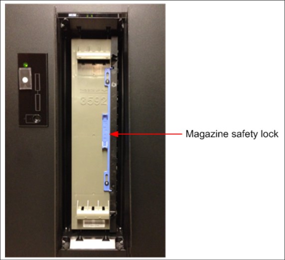
Figure 1-36 Tape cartridge magazine safety lock
When a magazine is removed from an I/O station, it is necessary to engage the safety lock until the magazine is placed on an accessible surface. It is then necessary to unlock the magazine to insert or remove cartridges. Attempting to insert or remove cartridges while the magazine safety lock is engaged might damage the magazine or the cartridges.
After a magazine is reinserted into an I/O station, it is necessary to unlock the magazine so that the accessor can retrieve cartridges. The I/O doors do not close correctly if the magazine is not unlocked.
Figure 1-37 shows a full 3592, a full LTO magazine, and an empty 3592 magazine.

Figure 1-37 I/O magazines
Two more I/O stations can be installed in any Dx5 expansion frame by ordering FC 1652. This feature installs two I/O stations in one expansion frame. Each additional pair of I/O stations increases the maximum insert/eject throughput for the library. The maximum cartridge capacity for expansion frames with two I/O stations is reduced by 80 cartridges for Model D25 and by 88 cartridges for Model D55. Storage-only frames (models Sx5) do not support I/O stations.
You can remotely use the I/O station action menu, which is available from the System page of the TS4500 management GUI, to open and close the I/O station doors. At the library, you can press the eject button (which is numbered 1 in Figure 1-38 on page 46) to open and close the doors. When the doors are open, it is possible to manually remove and replace the cartridge magazine to insert or remove cartridges.
When the doors are closed, the cartridge accessor can access the cartridges. The lock status LED that is next to the eject button (numbered 2 in Figure 1-38 on page 46) indicates that the I/O station is locked because the accessor can insert or remove cartridges. Do not attempt to open the I/O station when the lock status indicator is illuminated.
Figure 1-38 shows the top I/O station and panels, which control and show the state of the I/O station.

Figure 1-38 I/O station LEDs and panels
|
Important: Do not tilt the magazine during installation. Not tiling the magazine avoids pushing the magazine through the I/O station and obstructing the accessor.
|
The I/O station controls and LEDs are listed in Table 1-14.
|
Important: Use only the eject button (which is numbered 1 in Figure 1-38 on page 46) or the management GUI to open and close the I/O station doors. Do not attempt to open or close the doors manually.
|
Table 1-14 I/O station (numbers correspond to Figure 1-38 on page 46)
|
Number
|
Function
|
|
1
|
Eject button.
|
|
2
|
•Open/close state.
•Off: Normal state.
•Flashing: Transitional state. Whenever the button is pushed, it flashes and goes off when the doors open, and it flashes and comes back on as a solid light if it is locked by a “code”.
•On solid: Locked.
|
|
3
|
Unload is required, or cartridges are present.
•Off: No cartridges are present.
•Flashing: The I/O station is full so an intervention is required.
•On: Several cartridges are present.
|
|
4
|
No magazine is present.
On solid: No magazine is present.
|
|
5
|
I/O fullness indicator (green)
|
|
6
|
I/O lock indicator (green)
|
If the I/O station is obstructed, the doors automatically reopen.
Each I/O station slot features a unique address to indicate its physical location. The I/O station slot address consists of two values: a frame number and a row number.
After you close the I/O station doors, the library automatically moves the cartridges into storage slots. How each cartridge is assigned to a logical library depends on the configured VOLSER ranges. For more information, see Figure 1-39 on page 48. The state of the cartridge is shown in bold.

Figure 1-39 I/O import sequence of a cartridge
TS4500 integrated management console
The IMC is a built-in platform for tools that are used to manage the TS4500 tape library.
The IMC, which includes an LCD panel and a keyboard with a touchpad or trackpoint, can be mounted on either end of your TS4500 tape library. A library controller card (LCC) and a power source are required within that end frame or within the adjacent frame. Alternatively, FC 2737 allows for the IMC to be mounted on a non-powered end frame; that is, more than one frame away from a powered frame. This feature can be installed during the installation of expansion frames in an initial library installation, or later when expansion frames are added to a library.
The IMC comes preinstalled with a system console application, which is a set of software tools that are used for local service and remote support of the attached TS4500 tape library. The system console application enables the IMC to provide service console capabilities, such as broadband Call Home.
The TS4500 management GUI runs on a web browser in kiosk mode on the IMC. Kiosk mode means that the menu bar, address bar, and stop and reload buttons of the browser are disabled. In addition, it is not possible to use bookmarks or multiple browser windows.
Figure 1-40 shows the IMC.

Figure 1-40 Integrated management console
For more information about the IMC, see 4.1, “Integrated management console” on page 186.
IMC power distribution unit
The TS4500 IMC power distribution unit (IMC PDU) provides power to the card cage power supply and to the TS4500 IMC.
The IMC PDU, as shown in Figure 1-41, is typically installed in the end frame of the library with the IMC or last frame with power.

Figure 1-41 IMC PDU
A new Model Sx5 feature (FC 2737) provides a separate IMC power source, which enables the IMC to be installed on an Sx5 frame where the power cable is not long enough to reach a Dx5 or Lx5 frame. The feature includes instructions for moving the IMC PDU from the Lx5 frame to the Sx5 frame with the IMC, and for attaching a separately ordered power cord to a client outlet at that Sx5 frame. The feature also includes two lengthy Ethernet cables to connect the IMC to the Lx5 frame LCC at any frame position.
Power cable hole
It is possible to route power cables through the top of a frame in the TS4500 tape library. This routing method is an alternative to routing the power cables through the bulkhead at the bottom rear of the TS4500 tape library. This routing method might be necessary if the equipment is installed on a non-raised (solid) floor or if a top rack is installed.
Fibre Channel cable hole
It is possible to route Fibre Channel cables from servers through the top of a frame in the TS4500 tape library. This routing method is an alternative to routing the Fibre Channel cables through the bulkhead at the bottom rear of the TS4500 tape library. This routing method might be necessary if the equipment is installed on a non-raised (solid) floor.
TS4500 frame control assembly
The frame control assembly (FCA) is standard on all base frames (Lx5) and optional on any Dx5 expansion frames. The FCA includes one library controller card (LCC), up to two library frame interconnect (LFI) cards, and two power supplies, both of which can provide power to the library and all drives in a frame. All of these components are connected by using two back plane cards (BPCs).
Figure 1-42 shows the FCA in the TS4500.

Figure 1-42 Frame control assembly
The library control card
The LCC is the management node card for the TS4500 tape library. This card is used for the Ethernet connection to all components in the library, including the user interface and IMC (see Figure 1-43).

Figure 1-43 Library control card
The LCC has redundancy capability. In multiple drive frame configurations, the library negotiates the primary LCC, which controls the management functions.
During the power-up process, a selection process occurs to select the primary LCC. The selection process considers the LCC with the best database capabilities and the best hardware capabilities. The hardware capabilities relate to I/O station control and frame types.
Each LCC knows how many LCCs are in the system. If only one LCC is in the system, this LCC becomes the primary LCC. If any primary LCC fails, any LCC card can resume operations as the primary LCC.
|
Note: Every Lx5 frame and a Dx5 frame with drives installed have an LCC installed. Sx5 frames or Dx5 frames without drives do not have an LCC installed.
|
Library frame interconnect cards
The LFI cards provide communication between the frames of the TS4500 tape library through cable connections. Each Lxx frame includes one LFI card. A second LFI is required if expansion frames are added. When you face the back of the frame, the LFI on the right is LFI-A and the LFI on the left is LFI-B. Both cards are identical, but connections differ depending on whether the card is LFI-A or LFI-B.
|
Note: From firmware version R1.3 and higher, two LFI cards must be installed in every frame.
|
Figure 1-44 shows the LFI card.

Figure 1-44 Library frame interconnect
|
Note: Do not use tools to tighten the screws on the LFI card connectors. The use of tools can result in cables not being correctly plugged or damage to the connectors.
|
Two versions of LFI cards are available: the new version is labeled R1.5 or higher. The LED behavior is different since the 1.5 versions. Consider the following points:
•Previous to V1.5, the SRC LED was always on. From version R1.5, the SRC LED is only on if the LFI is creating 40 V. Therefore, it is only on in select powered frames (up to three frames in a system) and is never on in an S-frame.
•The CAN LED on the previous version of LFI is replaced with an L-frame indicator, which is labeled LFRM. The LFRM LED is on, regardless of whether the machine is turned on, if AC power is supplied to the L-Frame. This LED is on in the L-frame only.
•On previous version LFI, the Ethernet LEDs were always on. When the Ethernet cable was plugged in, the LEDs changed color. On the R1.5 version, the Ethernet LEDs are off until plugged in. After it is plugged in, the right LED turns on solid, the link LED and the left LED flash, and the activity LED flashes during data transfer.
Power supplies
For models L25, D25, L55, and D55, the library offers the TS4500 frame control assembly power structure, which combines drive power, library power, and AC power cord capabilities. Each of the Lx5 and Dx5 frames comes with two power supplies. Model Sx5 frames do not have their own power supply. Instead, they share power with an Lx5 or Dx5 frame, as shown in Figure 1-45.

Figure 1-45 Power supply
Back plane cards
Each of the Lx5 and Dx5 frames comes with two BPCs. With a single frame configuration (or a configuration with no FCA control system), redundant power is provided for each BPC. If one BPC fails, the other BPC in the frame picks up the load for the failed BPC.
Patch panel
The patch panel that houses the cable connections to connect hosts to the tape drive is in the rear of the frame above the drives, as shown in Figure 1-46.

Figure 1-46 Fiber patch panel
Display panel
The display panel on the base frame of the TS4500 tape library houses the library power and pause buttons. It displays library and I/O status indicators, as shown in Figure 1-47.

Figure 1-47 Display panel
The indicators and buttons that are available on the display panel are listed in Table 1-15.
Table 1-15 Display panel component descriptions
|
Number
|
Component
|
|
1
|
Warning indicator (yellow)
|
|
2
|
Library beacon (blue)
|
|
3
|
Power indicator (green)
|
|
4
|
Upper I/O fullness indicator (green)
|
|
5
|
Power switch
|
|
6
|
Power switch cover
|
|
7
|
Upper I/O lock indicator (green)
|
|
8
|
Lower I/O fullness indicator (green)
|
|
9
|
Lower I/O lock indicator (green)
|
|
10
|
Pause button
|
|
11
|
Library pause indicator (yellow)
|
|
12
|
Access recovery button
|
Expansion frames with optional installed I/O stations also feature a display panel. However, the panel on expansion frames does not include the library power button, as shown in Figure 1-48.

Figure 1-48 Expansion frame with I/O station
Pause button
You pause the library by pressing the pause button on the display panel (number 10 in Figure 1-47 on page 53) on the base frame of your TS4500 tape library. This pause button causes the library to move the cartridge accessor to the base frame and pause operations for 30 seconds or while a frame door is open. The pause light next to the pause button stops flashing, and it illuminates solid to indicate that the library is paused (number 11 in Figure 1-47 on page 53).
Power button
The power button procedures are described in this section.
Power on
Complete the following steps to power on the TS4500 tape library to begin the library initialization sequence and bring the library to a ready state:
1. From the display panel on the base frame of the library, slide the plastic cover that protects the power button up to make available the button (number 6 in Figure 1-47 on page 53).
2. Press the power button (number 5 in Figure 1-47 on page 53) and wait to see that the green power indicator turns on and stays on.
The power button runs a power-on initialization sequence for approximately 2 minutes. During that time, the menus on the TS4500 management GUI are not available for use. After the power-on initialization sequence completes, the library performs an inventory of the tape cartridges.
Power off
Complete the following steps to power off the TS4500 tape library after normal operation, but not during an emergency:
1. Ensure that the host application removed cartridges from all drives and that the library is varied offline from the host (if the host is attached).
2. Pause the library by pressing the pause button on the display panel (number 10 in Figure 1-47 on page 53) on the base frame of your TS4500 tape library. This pause button causes the library to move the cartridge accessor to the base frame and pause operations for 30 seconds or while a frame door is open. The pause light next to the pause button stops flashing, and it illuminates solid to indicate that the library is paused (number 11 in Figure 1-47 on page 53).
The health status pod on the System page of the management GUI also shows when the library is paused.
3. From the display panel on the base frame of the library, slide the plastic cover that protects the power button up to make available the button (number 6 in Figure 1-47 on page 53).
4. Press the power button (number 5 in Figure 1-47 on page 53) and wait until the green power indicator light turns off.
|
Note: Always pause the library before you power it off. If you power off the library before you pause the library, the library might take longer to come online after the next power-on.
|
Access Recovery
The Access Recover button can be used to unlock the administrator password and can only be done from the front panel.
When you press the Access Recovery button, you have 15 minutes to log in to the library and reset the administrator password with a temporary password. You must enter a new administrator password when you log out and back in again.
Press the Access Recovery button (see Figure 1-47 on page 53) then, log in to the GUI by using admin for the user name and password.
The Library requests to change the temporal password before continuing.
Media verification
The TS4500 supports media verification, which is fully controlled by the TS4500 at a logical library level. Media verification is transparent to any software application that controls the library.
This feature can be used to verify any media for the ability to read all of the data that is on the selected media within a logical library. Media verification is set up to run automatically on a set date.
You can set a recurring schedule for verification by days, months, or years. After you set up media verification, you can verify a single medium before the set date, if required. For more information, see “Media verification” on page 258.
Web camera
After the mounting hardware feature is installed by an IBM service support representative (SSR), you can mount a web camera in any frame of a TS4500 tape library. Specific clearances are necessary to accommodate the mounting hardware and the camera.
The camera is client-supplied and it can be installed in any frame to visually monitor the location of the library’s robotics. FC 1530, Web Camera Mounting Hardware, is required to install a web camera. The maximum camera dimensions can vary. However, no part of the camera can extend more than 60 mm (2.36 in.) from the center of the tripod mount to ensure sufficient clearance so that the accessor movement is not obstructed.
The camera mount (FC 1530) can be mounted on the front or rear frame support.
Fire suppression
Each Dx5, Lx5, Sx5, and Sx4 frame in the TS4500 tape library has an area on the top where an opening can be cut to allow the entrance of pipes, conduits, or other parts to use for fire suppression. The installation of a fire-suppression system is the responsibility of the client.
The TS4500 tape library is constructed to allow the third-party installation of fire-suppression equipment. When you are deciding whether to implement fire-suppression equipment, see the local and national standards and regulations for more information.
|
Important: For advice about selecting a fire-suppression system that provides the correct level of coverage and protection, consult your insurance underwriter and local fire marshal (or local building inspector). IBM designs and manufactures equipment to internal and external standards that require certain environments for reliable operation. Because IBM does not test any equipment for compatibility with fire-suppression systems, IBM does not make compatibility claims of any kind nor does IBM provide suggestions about fire-suppression systems.
|
1.4 Feature codes for the TS4500
You can order FCs to install components in library frames or to enhance the capacity or capabilities of the library.
A client-setup unit (CSU) is a feature that you, as the client, can install when the feature is ordered as a field upgrade. If you choose not to install a CSU, IBM can install it for an extra charge. However, detailed installation instructions are included when you order and receive these features. The available FCs are listed in Table 1-16.
Table 1-16 Feature codes for the frame models of the TS4500 tape library
|
Feature code
|
Model
|
CSU
|
Description
|
|
0983
|
Lx5, Dx5, 60F, TR1, TR2
|
No
|
TAA compliance
|
|
1404
|
L25, L55
|
No
|
TS1140 and TS1150 tape drive support
This FC triggers the shipment of a JK diagnostic cartridge.
When Model L25 is ordered, FC 1404 is required.
When FC 9080 (Mixed Media) is ordered for the Model L55, FC 1404 is required.
|
|
1405
|
L25, L55
|
Both
|
LTO-6 and LTO-5 tape drive support
This FC triggers the shipment of an L5 diagnostic cartridge. When model L55 is ordered, a minimum of one of FC 1405 or 1407 is required but both can be selected. When FC 9080 (Mixed Media) is ordered for model L25, a minimum of one of FC 1405 or 1407 is required but both can be selected.
|
|
1406
|
L25, L55
|
No
|
TS1160, TS1155, and TS1150 tape drive support
This FC triggers the shipment of a JL CE cartridge. When model L25 is ordered or when FC 9080 (Mixed Media) is ordered for model L55 a minimum of one of FC 1404 or 1406 is required but any can be selected.
|
|
1407
|
L25, L55
|
No
|
LTO-7 and LTO-6 tape drive support
This FC triggers the shipment of an L6 CE cartridge. When model L55 is ordered, a minimum of one of FC 1405 or 1407 is required but both can be selected. When FC 9080 (Mixed Media) is ordered for model L25, a minimum of one of FC 1405 or 1407 is required but both can be selected.
|
|
1408
|
L25, L55
|
No
|
LTO-8 and LTO-7 tape drive support
This FC triggers the shipment of an L7 CE cartridge. When model L55 is ordered, a minimum of one of FC 1407 or 1408 is required but both can be selected. When FC 9080 (Mixed Media) is ordered for model L25, a minimum of one of FC 1407 or 1408 is required but both can be selected.
|
|
1442
|
D25, D55, L25, L55
|
No
|
Dual accessors
This FC triggers the shipment of the following components:
•Four CE/diagnostic cartridges (two cartridges of the latest generation for both LTO and 3592).
•Service Bay Stop-A-related parts and Service Bay Stop-B-related parts.
•TS4500 Accessor B, including scanner, enhanced grippers, and enhanced node cards.
A maximum of one HA kit (FC 1442) per library can be ordered.
|
|
1450
|
D25, D55
|
No
|
TS4500 frame control assembly (FCA)
This FC Includes 1x LCC and 2x power supplies.
|
|
1460
|
L25, L55
|
No
|
Redundant Accessor Power/Network
This feature provides power and internal network redundancy for the L25/L55 frame. This is a prerequisite to FC 9002.
|
|
1530
|
D25, D55, L25, L55, S25, S55
|
No
|
Web camera mounting hardware. Provides mounting hardware only.
|
|
1531
|
D25, D55, L25, L55
|
No
|
First quad drive mounting kit
This feature provides signal and power cabling for a column of 4 adjacent drives. Fiber cables can be ordered by using one of the following FCs:
•FC 1536, MMF Quad Drive-to-Patch Panel cables
•FC 1537, SMF Quad Drive-to-Patch Panel cables
•FC 9713, No Patch Panel Cables
Prerequisites:
•Models L25/D25: One FC 1536 or 9713 is required
•Models L55/D55: One FC 1536 or 1537 or 9713 is required.
•Models D25/D55: FC 1450 is required
|
|
1532
|
D25, D55, L25, L55
|
No
|
Second quad drive mounting kit
This feature provides signal and power cabling for a column of 4 adjacent drives. Fiber cables can be ordered by using one of the following FCs:
•FC 1536, MMF Quad Drive-to-Patch Panel cables
•FC 1537, SMF Quad Drive-to-Patch Panel cables
•FC 9713, No Patch Panel Cables
This feature is not supported in the leftmost frame of a dual accessor library.
Prerequisites:
•Models L25/D25: One FC 1536 or 9713 is required
•Models L55/D55: One FC 1536 or 1537 or 9713 is required
•FC 1521 or 1531 is required
|
|
1533
|
D25, D55, L25, L55
|
No
|
Third quad drive mounting kit
This feature provides signal and power cabling for a column of 4 adjacent drives. Fiber cables can be ordered by using one of the following FCs:
•FC 1536, MMF Quad Drive-to-Patch Panel cables
•FC 1537, SMF Quad Drive-to-Patch Panel cables
•FC 9713, No Patch Panel Cables
This feature is not supported in the leftmost or rightmost frame of a dual accessor library.
Prerequisite:
•Models L25/D25: One FC 1536 or 9713 is required
•Models L55/D55: One FC 1536 or 1537 or 9713 is required.
•FC 1522 or 1532 is required
|
|
1534
|
D25, D55, L25, L55
|
Both
|
Fourth quad drive mounting kit
This feature provides signal and power cabling for a column of 4 adjacent drives. Fiber cables can be ordered by using one of the following FCs:
•FC 1536, MMF Quad Drive-to-Patch Panel cables
•FC 1537, SMF Quad Drive-to-Patch Panel cables
•FC 9713, No Patch Panel Cables
This feature is not supported in the leftmost frame of a single accessor library.
This feature is not supported in the leftmost or rightmost frame of a dual accessor library. Prerequisites:
•Models L25/D25: One FC 1536 or 9713 is required
•Models L55/D55: One FC 1536 or 1537 or 9713 is required
•FC 1523 or 1533 is required
|
|
1536
|
D25, D55, L25, L55
|
Both
|
MMF Quad Drive-to-Patch Panel Cables
This feature includes all fiber cables that are required for a column of four drives, 8x LC-LC Multimode Fibre (MMF) Drive-to-Patch Panel cables.
Prerequisite: One FC 1536 or 1537 or 9713 per each FC 1531, 1532, 1533, and 1534.
|
|
1537
|
D55, L55
|
Both
|
SMF Quad Drive-to-Patch Panel Cables
This feature includes all fiber cables that are required for a column of four drives, 8x LC-LC Single Mode Fibre (SMF) Drive-to-Patch Panel cables.
Prerequisite: One FC 1536 or 1537 or 9713 per each FC 1531, 1532, 1533, and 1534.
|
|
1604
|
L25, L55
|
Yes
|
Transparent LTO encryption
Provides license keys to enable transparent LTO encryption.
|
|
1628
|
L55
|
Yes
|
Additional LTO Cartridge Magazines
Provides magazine and cover for transport or storage of up to 18 cartridges.
|
|
1629
|
L25
|
Yes
|
Additional 3592 Cartridge Magazine
Provides magazine and cover for transport or storage of up to 16 cartridges.
|
|
1643
|
L25, L55
|
Yes
|
Intermediate CoD
Provides a license key to increase storage from entry capacity to intermediate capacity.
|
|
1644
|
L25, L55
|
Yes
|
Base CoD
Provides a license key to increase storage from intermediate capacity to base capacity. This feature code is a prerequisite for FC 9002 or Model Lx5 HD CoD FC 164x.
Prerequisite: FC 1643.
|
|
1645
|
S25
|
Yes
|
High-density CoD
|
|
1646
|
S55
|
Yes
|
High-density CoD
|
|
1647
|
L25
|
Yes
|
High-density CoD
Prerequisite: FC 1644.
|
|
1648
|
L55
|
Yes
|
High-density CoD
Prerequisite: FC 1644.
|
|
1649
|
D25
|
Yes
|
High-density CoD
|
|
1650
|
D55
|
Yes
|
High-density CoD
|
|
1652
|
D25, D55
|
No
|
Two additional I/O stations.
This feature adds 36 (LTO) or 32 (3592) I/O slots.
|
|
1663
|
D25, D55, L25, L55
|
No
|
Drive removal
One 3592 tape drive installation feature or one 3588 tape drive installation feature should be removed from the library frame when a tape drive is removed.
|
|
1682
|
L25, L55
|
Yes
|
Path failover
|
|
1742
|
S24, S54
|
No
|
TS4500 Control upgrade
This FC includes 1x top panel and 2x Ethernet cables, card cages, ASCs, BPCs, and LFIs.
|
|
1750
|
TR1, TR2
|
No
|
Left-side and right-side end covers
This feature is required only for the first top rack that is ordered (if multiple top racks are installed on adjacent frames).
|
|
1751
|
TR1
|
No
|
Power distribution unit
Provides one PDU to be mounted in the top rack.
The first PDU in a top rack does not consume any of the 10U of rack space. The second PDU in a top rack consumes 1U of rack space.
Consider the following points: •A maximum of two FC 1751s can be ordered.
•FC 1751 cannot be installed in the same rack as an FC 1752 PDU.
Each PDU has 10 C13 outlets that are divided into two groups of five outlets. Each group is protected by a 15 amp circuit breaker. In addition, a master 25 amp circuit breaker is available for the entire PDU. All of the circuit breakers are rated at 5 kAIC. Each PDU has a control input that can be used to turn all of the outlets on or off by an external switch or relay contact (not provided). The control input is defaulted to ON by a jumper plug that is included with the PDU.
Prerequisite: For each FC 1751 ordered, one power cord (FC 9954 - 9959 or 9966) must also be ordered.
Limitation: Mutually exclusive with 1752
|
|
1752
|
TR1, TR2
|
Yes
|
Enhanced PDU
Provides one PDU with 3-phase (wye) or single phase input power to be mounted in top rack (max of two can be ordered). The first PDU in a top rack does not use any of the 10U of rack space. The second PDU in a top rack consumes 1U of rack space.
Each PDU has nine outlets that are divided into three groups. Within each group, two C-13s and one C-19 outlets are used. Each group is protected by 20 amp circuit breakers that are rated at 10 kAIC. If required, loads that are installed in the TR1 with C14 inlets can be connected to the PDU C19 outlets by using C20 - C13 power cord FC 9949.
Prerequisites:
•For single phase input power, for each PDU ordered must order one power cord FC 9954 - 9958.
•For 3-phase (wye) input power, for each PDU ordered must order one power cord FC 9948.
Limitations: Mutually exclusive with 1751
|
|
1753
|
TR2
|
No
|
Olympus Rack Configuration
This feature specifies the configuration of the TR2 rack to be in conformance with the Open Compute Project Olympus Rack Specification.
This provides 5U of 19 inch rack space with three sets of EIA rails with a spacing from the front face of the front EIA rail to the rear face of the middle EIA rail being 745 mm (29.3 inches) and the spacing from the front face of the front EIA rail to the rear face of the rear EIA rail to be 1020 mm (41 inches). It includes a top cover that allows top access cables to be routed into the TR2. This also includes side air blocks that prevent airflow between the EIA rails and the side covers per the Open Compute Olympus Rack Specification.
|
|
1754
|
TR2
|
No
|
Standard 19 inch Rack Configuration
This feature specifies the configuration of the TR2 rack to be in conformance with industry standard 19-inch racks.
This provides 5U of 19 inch rack space with two sets of EIA rails with a spacing from the front face of the front EIA rail to the rear face of the rear EIA rail being 719 mm (28.3 inches).
It includes a top cover that allows top access cables to be routed into the TR2.
|
|
1755
|
TR2
|
Yes
|
Front Door
This feature provides the front door for the TR2
|
|
1756
|
TR2
|
Yes
|
Rear Door
This feature provides the rear door for the TR2
|
|
1802
|
L25, L55
|
No
|
Non-HA 1 - 2 frame X-Track Cable
|
|
1806
|
L25, L55
|
No
|
Non-HA 3 - 6 frame X-Track Cable
|
|
1814
|
L25, L55
|
No
|
Non-HA 7 - 14 frame X-Track Cable
Non-HA 7 to 14 Frame Track Cable. For more information, see 3584 X-Track Cable Features/Specify codes.
Limitation: Not supported by FC 2071 or FC 9071.
|
|
1818
|
L25, L55
|
No
|
Non-HA 9 - 18 frame X-Track Cable
Non-HA 9 to 18 Frame Track Cable. For more information, see 3584 X-Track Cable Features/Specify codes.
Limitation: Not supported by FC 2071 or FC 9071.
|
|
1909
|
L25, L55, D25, D55
|
No
|
Single power source bifurcated cable
This feature allows attachment of a powered frame to a single outlet while it maintains drive redundant power.
|
|
1951
|
D25, D55, L25, L55, S25, S55
|
No
|
Power distribution units
Provides two PCAs, mounting hardware including rack brackets, and internal power cables.
Supports any combination of up to three pairs of power cords for FC 4875 on the same frame and FC 9989 on adjacent frames.
Each PDU has 10 C13 outlets that are divided into two groups of five outlets. Each group is protected by a 15 amp circuit breaker. In addition, a master 25 amp circuit breaker is available for the entire PDU. All of the circuit breakers are rated at 5 kAIC. Each PDU has a control input that can be used to turn all of the outlets on or off by an external switch or relay contact (not provided). The control input is defaulted to ON by a jumper plug that is included with the PDU.
Corequisite: One power cord feature (FC 9954 - 9959 or 9966)
Limitation: FC 1951 cannot be installed in the same rack as an FC 1952 PDU.
|
|
1952
|
D25, D55, L25, L55, S25, S55
|
No
|
Enhanced PDUs
Provides two PDUs with 3-phase (wye) or single phase input power, mounting hardware including rack brackets, and internal power cables to provide power to the local frame control assembly.
These power cord features might require different customer facility outlets than frames without FC 1952. Can be used for adjacent frame AC power cord aggregation, or for unique facility AC socket requirements. Supports any combination of up to three pairs of power cords for FC 9989 on adjacent frames.
Each PDU has nine outlets that are divided into three groups. Within each group, two C-13s and one C-19 outlets are used. Each group is protected by 20 amp circuit breakers that are rated at 10 kAIC. If required, loads that are installed in the TR1 with C14 inlets can be connected to the PDU C19 outlets by using C20 - C13 power cord FC 9949.
Prerequisites:
•For single phase input power, must order one power cord FC 9954 - 9958.
•For 3-phase (wye) input power, must order one power cord FC 9948.
Limitations:
•Mutually exclusive with legacy PDU FC 1951, Fibre Channel switch mounting FC 4879, and Ethernet switch FC 2704.
•Mutually exclusive with FC 4879 or 2704.
|
|
2002
|
L25, L55
|
No
|
1 - 2 Frame Flex Track Cable A
|
|
2006
|
L25, L55
|
No
|
3 - 6 Frame Flex Track Cable A
|
|
2014
|
L25, L55
|
No
|
7 - 14 Frame Flex Track Cable A
|
|
2018
|
L25, L55
|
No
|
9 - 18 Frame Flex Track Cable A
|
|
2071
|
L25, L55
|
No
|
Flex track guide
This FC includes AXY, AXY plate, ASC to Flex track cable and new end stops.
|
|
2072
|
D25, D55, S25, S55, S24, S54
|
No
|
Flex track guide for expansion frame
|
|
2309
|
D25, D55, L25, L55
|
No
|
TS4500 Accessor Refresh
This FC provides complete accessor assembly with HD grippers to Lxx models or models with FC 1442.
Prerequisite: FC 2071, FC 2072, or FC 9071, FC 9072.
|
|
2402
|
L25, L55
|
No
|
1 - 2 Frame Flex Track Cable B
|
|
2406
|
L25, L55
|
No
|
3 - 6 Frame Flex Track Cable B
|
|
2414
|
L25, L55
|
No
|
7 - 14 Frame Flex Track Cable B
|
|
2418
|
L25, L55
|
No
|
9 - 18 Frame Flex Track Cable B
|
|
2704
|
D25, D55, S25, S55, S24, S54
|
No
|
Console expansion 26-port Ethernet switch, rack mount
Provides a 26-port Ethernet switch and attachment cable for connection to an IMC as a centralized system console.
Up to 24 extra connections of FC 2715 are provided by this feature. This feature is supported on Lx5 models to allow other products to share the IMC.
|
|
2715
|
L25, L55
|
No
|
TSSC attachment cable
FC 2715 is a cable to attach a unit to the Ethernet switch that is provided by the TSSC.
Note:
•A maximum of 43 of FC 2715 can be included in a single TSSC facility.
•FC 2704 is supported on Lx5 models if you are connecting the frame to a TSSC.
|
|
2735
|
L25, L55
|
No
|
USB Optical Drive
Required for all new plant orders. This feature provides a USB optical drive for use with the integrated management console (IMC). The optical drive is required for IMC code and service IBM Documentation updates.
|
|
2737
|
S25, S55
|
No
|
IMC Separate Power Source.
This feature allows longer distances between the IMC end panel and an FCA by supplying 2 Ethernet cables that are longer than normal. For both plant and field, instructions are also provided for moving the IMC PDU from another frame into this frame.
Prerequisite: One of the FC 9970-9985, 9989 power cords.
|
|
4879
|
L25, D25, TR1, TR2
|
No
|
TS7700 BE Switch Mounting Hardware
This feature provides 2x Fibre Channel switch mounting hardware, including rack brackets and power cords.
Prerequisite: FC 4880
|
|
4880
|
L25, D25, TR1, TR2
|
No
|
TS7700 BE 16 Gb Switch
Provides 1x Fibre Channel switch (16 Gb).
Limitation: A maximum of 2x FC 4880 per model x25 can be used.
|
|
4892
|
D25, D55, L25, L55, S25, S55
|
No
|
Rear Door Sensor
This feature provides rear door sensor components for notifying of rear door open/close events.
|
|
6013
|
D25, D55, L25, L55
|
Yes
|
LC to LC Fibre Channel cable - 13 m (43 ft.)
|
|
6025
|
D25, D55, L25, L55
|
Yes
|
LC to LC Fibre Channel cable - 25 m (82 ft.)
|
|
6061
|
D25, D55, L25, L55
|
Yes
|
LC to LC Fibre Channel cable - 61 m (200 ft.)
|
|
8750
|
D55, L55
|
No
|
LTO cleaning cartridge
|
|
8802
|
D25, L25
|
No
|
3592 cleaning cartridge
|
|
9001
|
D25, D55, L25, L55
|
No
|
Driveless frame
|
|
9002
|
L25, L55
|
No
|
First expansion frame attachment
This feature is used as a part of the process to add any Dxx or Sxx frame.
Prerequisites:
•FC 1460 and FC 1644
•FC 9001 for Lxx models
|
|
9003
|
L25, L55
|
No
|
Additional expansion frame attachment
This feature is used as a part of the process to add any Dxx or Sxx frame.
|
|
9040
|
L25, L55
|
No
|
High availability library
Prerequisites:
One Flex-track A and B cable of the same length
Flex-Track A cable: FC 2002, 2006, 2014, or 2018
Flex-Track B Cable: FC 2402, 2406, 2414, or 2418
|
|
9071
|
L25, L55
|
No
|
Flex Track Guide Base
This feature includes AXY, AXY plate, ASC to Flex track cable and new end stops.
Prerequisite: FC 2002 or FC 2006 or FC 2014 or FC 2018.
|
|
9072
|
D25, D55, S25, S55, S54, D54
|
No
|
Flex Track Guide for expansion frame
|
|
9073
|
D25, D55, L25, L55, S25, S55
|
No
|
3-Phase PDU Capable
This feature indicates that the frame can support Enhanced PDUs and their associated power cords. FC 9073 is a prerequisite for ordering FC 1952.
|
|
9080
|
L25, L55
|
No
|
Mixed Media Library.
Prerequisite: Library contains a mix of LTO and 3592 frames.
For Model L25, FC 1628 (LTO Magazine) and a minimum of one of FC 1405 or FC 1407 (LTO CE cartridge).For Model L55, FC 1629 (3592 Magazine) and FC 1404 (3592 CE cartridge).
Limitation: Mixed media is not supported for Lx2/Lx3.
|
|
9210
|
L25, L55
|
No
|
Attached to HP-UX system
|
|
9211
|
L25, L55
|
No
|
Attached to Solaris system
|
|
9212
|
L25, L55
|
No
|
Attached to Microsoft Windows system
|
|
9213
|
L25, L55
|
No
|
Attached to another system that is not an IBM system
|
|
9215
|
L25, L55
|
No
|
Attached to Linux system
|
|
9217
|
L25, L55
|
No
|
Attached to z/OS, TS7700
|
|
9218
|
L25, L55
|
No
|
Attached to High Performance Storage System (HPSS)
|
|
9400
|
L25, L55
|
No
|
Attached to IBM i5/OS or IBM OS/400® system
|
|
9600
|
L25, L55
|
No
|
Attached to IBM AIX® system
|
|
9607
|
D55, L55
|
No
|
3588 F7C plant installation
|
|
9609
|
D55, L55
|
No
|
3588 F8C plant installation
|
|
9611
|
D55, L55
|
No
|
3588 F8S plant installation
|
|
9613
|
D55, L55
|
No
|
3588 F9C plant installation
|
|
9615
|
D55, L55
|
No
|
3588 F9S plant installation
|
|
9617
|
D55, L55
|
No
|
3588 S9Cplant installation
|
|
9677
|
D25, L25
|
No
|
Plant Installation 3592 in a 3584 frame
This code notifies the plant to factory installation a new 3592 tape drive into a new 3584 tape library frame that is coming from the plant.
|
|
9689
|
D25, L25
|
Yes
|
Field Installation 3592 in a 3584 frame
This feature notifies the plant to ship one 3592 tape drive, which is field that is installed in a 3584 tape library frame.
|
|
9690
|
D25, D55, L25, L55
|
No
|
3588/3592 drive. Field install. FC 9690 is a counting feature code.
Prerequisite: FC 152x (drive mounting kit). Each FC 152x supports up to four
of FC 969x.
|
|
9692
|
L25, L55
|
No
|
3592 E07/EH7 tape drive. Plant install. FC 9692 is a manufacturing routing code.
Prerequisite: FC 152x (drive mounting kit).
|
|
9695
|
L55, D55
|
No
|
3588 F5A/F5C tape drive. Plant install. FC 9695 is a manufacturing routing code.
Prerequisite: FC 152x (drive mounting kit).
|
|
9697
|
L55, D55
|
No
|
3588 F6A/F6C tape drive. Plant install. FC 9697 is a manufacturing routing code.
Prerequisite: FC 152x (drive mounting kit).
|
|
9699
|
L25, D25
|
No
|
3592 EH8 tape drive - plant install
FC 9699 is a manufacturing routing code.
Prerequisite: FC 152x (drive mounting kit).
|
|
9700
|
D25, D55, L25, L55
|
No
|
No host attach cables (from plant)
|
|
9704
|
L55, D25
|
No
|
3592 55E tape drive. Plant install. FC 9704 is a manufacturing routing code.
Prerequisite: FC 152x (drive mounting kit).
|
|
9705
|
L55, D25
|
No
|
3592 55F tape drive. Plant install. FC 9705 is a manufacturing routing code.
Prerequisite: FC 152x (drive mounting kit).
|
|
9706
|
D25, L25
|
No
|
3592 60F tape drive - Plant Install in 3584
|
|
9707
|
D25, L25
|
No
|
3592 60E tape drive - Plant Install in 3584
|
|
9708
|
D25, L25
|
No
|
3592 60S tape drive - Plant Install in 3584
|
|
9713
|
D25, D55, L25, L55
|
Both
|
Direct Fiber - No Patch Panel Cables
This feature is specified whether you do not want the factory to ship any Fibre Channel cable FC 1536 “MMF Quad Drive-to-Patch Panel cables” or FC 1537 “SMF Quad Drive-to-Patch Panel cables”.
|
|
9726
|
D25, L25
|
Both
|
TS1160 tape drive - Field Install Drive in 3584
This feature field installs one 3592 Model 60E, 60F, or 60S tape drive into an installed 3584 Model D25 or L25. This feature is also required to field merge a 3592 Model 60E, 60F or 60S tape drive into a 3584 frame coming from the plant.
|
|
9735
|
L25, L55
|
No
|
IMC broadband Call Home
This feature originally indicated that the customer allows broadband Call Home; however, the feature code is no longer used.
|
|
9948
|
D25, D55, L25, L55, S25, S55, TR1, TR2
|
Both
|
3-Phase Power Cord
This feature provides a 4.3-meter (14-foot) long power cord with an IEC 309 3P+N+G 32A plug, which is rated for 230 Vac, 24 Amps. This power cord supports 3-phase (wye) power. To be used with Enhanced PDU FC 1752 or FC 1952.
|
|
9949
|
D25, D55, L25, L55, S25, S55, TR1, TR2
|
Both
|
C20-C13 Power Cord for spare outlets in the Enhanced PDU
This feature provides a 2.8 meters long C20-C13 Power Cord to be used between computer equipment and the Enhanced PDU Feature 1752 or 1952 or customer-supplied PDU with C19 outlets. C13 connects to the male C14 inlet or power cord plug and the C20 mates with the C19 receptacle on the Enhanced PDU. This power cord is intended to be used on PDUs with C19 outlets.
|
|
9954
|
D25, D55, L25, L55, S25, S55, TR1, TR2
|
No
|
NEMA L6-30 Power Cord
FC 9954 is used with PDU FCs 1751 or 1951. FC 9954 provides 1x power cord for FC 1751 and 2x power cords for FC 195x.
|
|
9955
|
D25, D55, L25, L55, S25, S55, TR1, TR2
|
No
|
RS 3750DP power cord
FC 9955 is used with PDU FCs 1751 or 1951. FC 9955 provides 1x power cord for FC 1751 and 2x power cords for FC 195x.
|
|
9956
|
D25, D55, L25, L55, S25, S55, TR1, TR2
|
No
|
IEC 309 power cord
FC 9956 is used with PDU FCs 1751 or 1951. FC 9956 provides 1x power cord for FC 1751 and 2x power cords for FC 195x.
|
|
9957
|
D25, D55, L25, L55, S25, S55, TR1, TR2
|
No
|
4.3 m power cord (Australia/NZ)
FC 9957 is used with PDU FCs 1751 or 1951. FC 9957 provides 1x power cord for FC 1751 and 2x power cords for FC 195x.
|
|
9958
|
D25, D55, L25, L55, S25, S55, TR1, TR2
|
No
|
4.3 m power cord (Korean)
FC 9958 is used with PDU FCs 1751 or 1951. FC 9958 provides 1x power cord for FC 1751 and 2x power cords for FC 195x.
|
|
9959
|
D25, D55, L25, L55, S25, S55
|
No
|
Unterminated power cord
FC 9959 is used with PDU FCs 1751 or 1951. FC 9959 provides 1x power cord for FC 1751 and 2x power cords for FC 195x.
|
|
9966
|
D25, D55, L25, L55, S25, S55
|
No
|
Unterminated power cords (China CCC cert)
FC 9966 is used with PDU FCs 1751 or 1951. FC 9966 provides 1x power cord for FC 1751 and 2x power cords for FC 195x.
|
|
9970
|
D25, D55, L25, L55, S25, S55
|
No
|
Dual 4.3 m power cord (international, 250 VAC 16A single phase, watertight connector, IEC-309)
FC 9970 includes model-dependent contents. For countries other than the US and Canada, the connector is rated at 16A (plug type Hubbell HBL316P6W or equivalent) for connection to Hubbell type HBL316R6W or equivalent receptacles.
In the US and Canada, the connector is rated at 20 A (plug type Hubbell HBL320P6W) for connection to Hubbell type HBL320R6W or equivalent receptacles. This power cord is the default power cord for all countries other than those countries that are specified for FC 9972 and FCs 9976 - 9983.
This power cord can be used for the following countries:
•Argentina
•Australia
•Brazil
•Canada
•China
•Japan
•Korea
•New Zealand
•Philippines
•South Africa
•Taiwan
Note: Only 1 power cord is shipped for an S25 and S55 to be used with FC 2737
|
|
9972
|
D25, D55, L25, L55
|
No
|
Dual 4.3 m power cords (250 VAC 15, non-watertight twist lock connector, Nema L6-15P mates with L6-15R).
FC 9972 includes model-dependent contents. It is the default power cord for US, Canada, Japan, Korea, Philippines, and Taiwan.
Note: Only 1 power cord is shipped for an S25 and S55 to be used with FC2737.
|
|
9976
|
D25, D55, L25, L55
|
No
|
Dual 4.3 m power cords with 10 Amp/250 Vac, non-watertight IRAM 2073 plug (Argentina).
Note: Only 1 power cord is shipped for an S25 and S55 to be used with FC2737
|
|
9977
|
D25, D55, L25, L55
|
No
|
Dual 4.3 m power cords with 15 Amp/250 Vac with earth pin InMetro NBR 14136 plug (Brazil).
Note: Only 1 power cord is shipped for an S25 and S55 to be used with FC2737.
|
|
9978
|
D25, D55, L25, L55
|
No
|
Dual 4.3 m power cords with 10 Amp/250 Vac AZ/NZS 3112/2000 plug (Australia and New Zealand).
Note: Only 1 power cord is shipped for an S25 and S55 to be used with FC2737.
|
|
9979
|
D25, D55, L25, L55
|
No
|
Dual 4.3 m power cords with 15 Amp/250 Vac JIS C8303, C8306 plug (Japan).
Note: Only 1 power cord is shipped for an S25 and S55 to be used with FC2737. |
|
9980
|
D25, D55, L25, L55
|
No
|
Dual 4.3 m power cords with 10 Amp/250 Vac, GB 2099.1, 1002 plug (China).
Note: Only 1 power cord is shipped for an S25 and S55 to be used with FC2737.
|
|
9981
|
D25, D55, L25, L55
|
No
|
Dual 4.3 m power cords with 15 Amp/250 Vac with earth pin KS C8305, K60884-1 plug (Korea).
Note: Only 1 power cord is shipped for an S25 and S55 to be used with FC2737.
|
|
9982
|
D25, D55, L25, L55
|
No
|
Dual 4.3 m power cords with 10 Amp/250 Vac CNS 10917-3 plug (Taiwan).
Note: Only 1 power cord is shipped for an S25 and S55 to be used with FC2737.
|
|
9983
|
D25, D55, L25, L55
|
No
|
Dual 4.3 m power cords with 10 Amp/250 Vac SANS 164-1 plug (South Africa).
Note: Only 1 power cord is shipped for an S25 and S55 to be used with FC2737.
|
|
9984
|
D25, D55, L25, L55
|
No
|
Dual 4.3 m power cords with 15 A/250V single phase power cord assemblies, NEMA L6-20P non-watertight twistlock 20A plug.
FC 9984 is 2x power cords, which are UL/CSA certified for use in US and Canada. These power cords mate with client-supplied NEMA L6-20R receptacles.
Note: Only 1 power cord is shipped for an S25 and S55 to be used with FC2737.
|
|
9985
|
D25, D55, L25, L55
|
No
|
Dual 4.3 m power cords with 15 A/250V single phase power cord assemblies with watertight 15A Russellstoll plug.
FC 9985 is 2x power cords, which are UL/CSA certified for use in US and Canada. These power cords mate with client-supplied Russellstoll 3743U2 or 9R23U2W receptacles.
Note: Only 1 power cord is shipped for an S25 and S55 to be used with FC2737.
|
|
9989
|
D25, D55, L25, L55
|
No
|
Dual 4.3 m power cords with 10A/250V with IEC 309 C14 plug.
FC 9989 is for use with adjacent frame PDUs (FC 1951) or external (client-supplied) PDUs.
Note: Only 1 power cord is shipped for an S25 and S55 to be used with FC2737.
|
|
AGKQ
|
L25, D25, L55, D55
|
No
|
3 Meter OM3 Fiber Quad Cables (LC)
Provides two space-efficient 3 m (9.8-foot) bundles (of four cables each) to connect four drives to a fiber switch in the same or one frame away, or in a TR1 top rack.
To attach tape drives in the same frame or 1 frame away from a model x25 frame containing TS7700 BE switches, order one of this feature code for each quaddrive mounting kit to be connected.
For xx5 models, each FC AGKQ has a prerequisite of an associated FC 152x or 153x.
|
|
AGK1
|
D25, D55, L25, L55
|
No
|
10-meter OM3 fiber Cable (LC)
This feature provides a 10-meter (32.8-foot) 50.0/125 micrometer fiber optic cable that is terminated with LC Duplex connectors.
|
|
AGK2
|
D25, D55, L25, L55
|
No
|
25-meter OM3 fiber Cable (LC)
This feature provides a 25-meter (82-foot) 50.0/125 micrometer fiber optic cable that is terminated with LC Duplex connectors.
|
|
AGK3
|
D25, D55, L25, L55
|
No
|
80-meter OM3 fiber Cable (LC)
This feature provides an 80-meter (262-foot) 50.0/125 micrometer fiber optic cable that is terminated with LC Duplex connectors.
|
For more information about ordering media, see Ordering LTO cartridges and media supplies and Ordering 3592 cartridges and media supplies in IBM Documentation.
1.5 Host platforms and device drivers
The TS4500 tape library is supported on many operating systems. For a current list of host software versions and release levels that support the TS4500 tape library, see the IBM System Storage Interoperation Center (SSIC) web page to confirm support and to check for all required firmware and drivers.
To download the required drivers, see IBM Fix Central.
Feature codes for operating systems
The following no-charge specify feature codes indicate the server platform to which the TS4500 tape library is attached. These features are used by IBM for device driver distribution:
•FC 9210: Attached to HP-UX
•FC 9211: Attached to Sun system
•FC 9212: Attached to Windows system
•FC 9213: Attached to another system that is not an IBM system
•FC 9215: Attached to Linux system
•FC 9217 Attached to IBM System z®, TS7700
•FC 9218: Attached to High Performance Storage System (HPSS)
•FC 9400: Attached to IBM System i
•FC 9600: Attached to IBM System p
More than one platform-attached features can be chosen because the library can be attached to more than one of these platforms. Only one of each feature is added; that is, only one FC 9212 is required if two or more Windows servers use the TS4500.
|
Tip: The device driver is available for each operating system from IBM Fix Central.
|
1.6 Specifications
The TS4500 tape library is a stand-alone tape subsystem that consists of one or more frames. It can expand in a modular manner to provide large capacities. The frames join side-to-side, and they can be added on the left side or right side of the installed frames.
1.6.1 Physical specifications
The physical dimensions of the TS4500 tape library frames are listed in Table 1-17.
Table 1-17 Physical dimensions
|
Model
|
Width1
|
Depth
|
Height
|
|
L25, L55, D25, D55, S25, S55, S24, and S54 (on casters)
|
782 mm (30.8 in.)
|
1,212 mm (47.72 in.)
|
1,800 mm (70.9 in.)
|
|
L25, L55, D25, D55, S25, S55, S24, and S54 frames with top rack
|
782 mm (30.8 in.)
|
1,212 mm (47.72 in.)
|
2,320 mm (91.34 in.)
|
|
L25, L55, D25, D55, S25, S55, S24, and S54 frame with covers
|
782 mm (30.8 in.)
|
1,212 mm (47.72 in.)
|
1,800 mm (70.9 in.)
|
|
L25, L55, D25, D55, S25, S55, S24, and S54 frame without covers
|
725 mm (28.5 in.)
|
1,212 mm (47.72 in.)
|
1,800 mm (70.9 in.)
|
1 Frame width only. Extra interframe spacing of 30 mm (1.2 in.) is required.
The weights of the frames according to the number of installed drives, robotics, and tape cartridges are listed in Table 1-18.
Table 1-18 TS4500 tape library weight
|
Model and position
|
Minimum weight of frame (with no tape drives or cartridges)1
|
Maximum weight of frame (with maximum tape drives and cartridges) 2
|
|
L25 Position 1 (leftmost frame)
|
407.8 kg (899 lb.)
|
586.5 kg (1,293 lb.)
|
|
L25 Position 2+
|
407.8 kg (899 lb.)
|
630.5 kg (1,390 lb.)
|
|
D25 Position 1 (leftmost frame)
|
310.7 kg (685 lb.)
|
500 kg (1,103 lb.)
|
|
D25 Position 2+
|
310.7 kg (685 lb.)
|
552.5 kg (1,218 lb.)
|
|
L55 Position 1 (leftmost frame)
|
410 kg (904 lb.)
|
592 kg (1,305 lb.)
|
|
L55 Position 2+
|
410 kg (904 lb.)
|
637 kg (1,404 lb.)
|
|
D55 Position 1 (leftmost frame)
|
316 kg (697 lb.)
|
503.5 kg (1,110 lb.)
|
|
D55 Position 2+
|
316 kg (697 lb.)
|
557 kg (1,228 lb.)
|
|
S25 Position 1 (leftmost frame)
|
299 kg (660 lb.)
|
491.2 kg (1,083 lb.)
|
|
S25 Position 2+
|
299 kg (660 lb.)
|
540.2 kg (1,191 lb.)
|
|
S55 Position 1 (leftmost frame)
|
304 kg (670 lb.)
|
509.4 kg (1,123 lb.)
|
|
S55 Position 2+
|
304 kg (670 lb.)
|
564 kg (1,244 lb.)
|
|
S24 Position 2+
|
285.8 kg (630 lb.)
|
526.2 kg (1160 lb.)
|
|
S54 Position 2+
|
290.3 kg (640 lb.)
|
562.5 kg (1240 lb.)
|
|
TR1 Weight of top rack (empty)3
|
24.5 kg (54 lb.)
|
24.5 kg (54 lb.)
|
|
Weights that are listed for the Lx5 frames include the accessor, IMC, side doors, and side panels. After the initial library installation, these parts can be moved to other frames within the library string to shift part of the weight to other frames.
| ||
1 Frames in position 1 (the leftmost frame in a library string) can have a maximum of 12 tape drives.
2 Drive frames in positions 2+ can accommodate 16 tape drives.
3 A top rack can be installed optionally on any HD frame. Side panels and PDUs are also optional. Each side panel adds 6.8 kg (15 lb.). Each PDU adds 4.5 kg (10 lb.).
When you plan for the installation, the space implications in the computer room must be considered for the possibility of adding frames in the future.
1.6.2 Floor requirements
The library must be installed on a raised or solid floor. The floor must have a smooth surface and, if raised, the floor must not have ventilation panels beneath the leveling jackscrews. If carpeted, it must be confirmed that the carpet is approved for computer-room applications. To accommodate unevenness in the floor, the leveling jackscrews can be raised or lowered to the following specifications:
•The maximum allowable variance must not exceed 7 mm (0.27 in.) per 76 mm (3 in.).
•The maximum out-of-level condition must not exceed 40 mm (1.6 in.) over the entire length and width of the library.
The floor on which the library is installed must support the following weight specifications:
•Up to 4.8 kilograms per square cm (68.6 lbs. per square inch) of point loads that are exerted by the leveling jackscrews
•Up to 211 kilograms per square meter (43.4 lbs. per square foot) of overall floor loading
The number of point loads that is exerted depends on the number of frames that makes up the library. Four point loads are on each frame (at the corners of each frame).
For more information, see the IBM TS4500 Introduction and Planning Guide, SC27-5990.
1.6.3 Operating environment
For more information about environmental specifications, see this IBM Documentation web page.
1.6.4 Power and cooling specifications
Power for the components of the TS4500 tape library is provided by a power supply within the Lx5 or Dx5 frame. The Lx5 power supply provides power to the components that are housed in the Lx5 frame. The Dx5 power supply provides power to the components in the Dx5 frame. The Sx5 models receive their power supply from an adjacent frame (an Lx5 or Dx5, depending on the configuration).
Models Lx5 and Dx5 of the TS4500 tape library with installed PDUs (FC 1951) can power to two adjacent frames by specifying a power cord (FC 9989) on each of the adjacent frames and plugging the cords into the spare outlets on the (FC 1951) PDUs, which are on the adjacent Lx5 or Dx5 frame.
Figure 1-49 shows the first adjacent frame cord that is plugged into the PDU receptacles and the second adjacent frame power cord that is plugged into the consecutive PDU receptacles. The adjacent frames that receive power through FC 9989 can be up to three frames away from the frame with FC 1951. By using adjacent frame power cords, clients can power to three frames from only two facility outlets.

Figure 1-49 FC 9989 cable positions with FC 1951
The power requirements for the Lx5 and Dx5 frames are listed in Table 1-19.
Table 1-19 Power requirements for the TS4500 tape library
|
Description
|
Power consumption (Watts)
|
Cooling
Requirements
(Btu per hr,
maximum
continuous)a
| ||
|
Off 2
|
Idle
|
Maximum continuous (not peak)
| ||
|
Models, power per frame
| ||||
|
11
|
95
|
130
|
433
| |
|
0
|
11
|
11
|
38
| |
|
Feature Codes
| ||||
|
FC 1442 HA Kit w/Second Accessor
|
0
|
24
|
85
|
290
|
|
FC 1450 (TS4500 FCA) including one LCC and two AC/DC power supplies
|
11
|
38
|
38
|
130
|
|
FC 1460 (second LFI for Lx5 frame in a multiple frame network)
|
0
|
5
|
5
|
17A
|
|
FC 1521, 1523, 1524
(quad drive mounting kits)
|
0
|
3
|
3
|
10
|
|
FC 1751 PDU
(for TR1 top rack)
|
9
|
9
|
9
|
31
|
|
FC 1951 PDU
|
17
|
17
|
17
|
58
|
|
Drives, power is per drive
| ||||
|
TS1140f
|
0
|
28
|
50
|
171
|
|
TS1150f
|
0
|
23
|
48
|
164
|
|
TS1155 55Ff
|
0
|
23
|
48
|
164
|
|
TS1155 55Ef
|
0
|
50
|
63
|
215
|
|
TS1160E6
|
0
|
38
|
62
|
211
|
|
TS1160Ff
|
0
|
39
|
63
|
215
|
|
TS1160Sf
|
0
|
38
|
62
|
211
|
|
TS1050f
|
0
|
16
|
32
|
109
|
|
TS1060f
|
0
|
13
|
36
|
123
|
|
TS1070f
|
0
|
15
|
31
|
106
|
|
TS1080f
|
0
|
18
|
40
|
136
|
|
TS1090f
|
0
|
18.5
|
42
|
143
|
1 To calculate the total cooling that is required by the library (in Btu per hr), multiply the total power in watts by 3.41. To convert Btu per hr to kBtu per hr, divide your result by 1000.
2 Off refers to power consumed when the library is connected to an AC power source and the library on/off switch is set to off.
3 Lx5 models and models with FC 1450 or FC1951 are equipped with dual AC power cords. The figures in the table show the total power that is consumed, including power that is consumed by redundant power supplies. Each power cord supplies approximately half of the power.
4 Lx5 frame power includes all frame loads, cartridge accessor, IMC, and display.
5 For base models that do not include FC 1450 (TS4500 FCA), the power consumption that is shown in the table figures is power that is provided by other frames. The figures include power consumption for the lighting and two LFIs.
6 Idle power is consumed when the drive has no tape cartridge loaded. Maximum continuous power is consumed when the drive is actively reading and writing to the tape. These power consumption values include the power that is required for the cooling fan at normal speed. In ambient environments that are hotter than the recommended range, the cooling fan might speed up and draw more power.
For more updated information to calculate power consumption with drives, see this IBM Documentation web page.
The environmental specifications for the TS4500, which refers to the hardware of the TS4500 tape library, and might lead to temperatures greater than allowable for the cartridges and media that are stored in the library, are listed in Table 1-20.
Table 1-20 Equipment environment specifications for the TS4500 tape library
|
Product operation
|
Product power off
| |||||||
|
Dry-bulb temperature1
|
Relative Humidity
(Non-condensing)
|
Maximum Wet-bulb temp.
|
Maximum
elevation
|
Dry-bulb
temp.
|
Relative
humidity
(% RH)
|
Maximum Wet-bulb
temp.
| ||
|
Allowable
|
Recommended
|
Allowable
(% RH)
|
Recommended
(% RH)
| |||||
|
16 - 32°C
|
16 - 25°C
|
20 - 80%
|
20 - 50%
|
26°C
|
3050 m
|
5 - 45°C
|
5 - 80%
|
28°C
|
1 Derate maximum dry-bulb temperature 1°C/300 m (1.8°F/984 ft.) above 900 m (2 953 ft.).
Data processing design criteria uses a preferred controlled environment of 22° C at 45% relative humidity for the most reliable operation and performance. However, recommended operating limits extend 18 - 27° C and 40% - 60% RH or 5.5° C DP-Dew Point - 15° C DP. (ASHRAE 2016 TC9.9) Best performance is not obtained if the environment swings from limit to limit.
For frames that contain LTO tape cartridges or IBM 3592 Enterprise Tape Cartridges, see their environmental and shipping specifications for these products and adjust the operating environment for the library accordingly.
For more information about planning the installation of the TS4500, see this IBM Documentation web page.
..................Content has been hidden....................
You can't read the all page of ebook, please click here login for view all page.