

IBM z14 ZR1 hardware overview
This chapter expands on the description of the key hardware elements of the z14 ZR1 that was presented in Chapter 1, “The foundation of a trusted digital transformation” on page 1. It includes the following topics:
2.1 Models and upgrade paths
The z14 Model ZR1 features an assigned machine type (MT) of 3907, which uniquely identifies the central processor complex (CPC). All z14 ZR1 use processor units single chip modules (PU SCMs, up to four per system, feature driven) with five, six, seven, eight, or nine active processor unit cores. Spare processor units, system assist processors (SAPs), and one integrated firmware processor (IFP) are integral to the z14 ZR1 system.
The z14 ZR1 is based on four new feature codes: Max4, Max12, Max 24, and Max30. The feature codes determine the maximum number of characterizable processor units available in the CPC drawer.
The number of characterizable processor units, SAPs, and spare processor units for the various models is listed in Table 2-1. For more information about processor unit characterization, see “PU characterization” on page 23.
Table 2-1 z14 ZR1 summary (machine type 3907)
|
Feature name
|
Feature code
|
Characterizable processor units
|
Standard SAPs
|
Spares
|
Integrated firmware processor
|
|
Max4
|
0636
|
1 - 4
|
2
|
1
|
1
|
|
Max12
|
0637
|
1 - 12
|
2
|
1
|
1
|
|
Max24
|
0638
|
1 - 24
|
2
|
1
|
1
|
|
Max30
|
0639
|
1 - 30
|
2
|
1
|
1
|
The upgrade paths for the z14 ZR1 are shown in Figure 2-1. Because of the new design of the z14 ZR1, no supported migration path to any of the z14 models is available.

Figure 2-1 z14 ZR1 upgrade paths
On the z14 ZR1, concurrent processor upgrades (for more information, see in Chapter 4, “Strengths of the z14 ZR1” on page 59) are available for CPs, IFLs, ICFs, Z-Integrated Information Processors (zIIPs), and SAPs. However, concurrent processor unit upgrades require that more processor units are physically installed, but not activated at a previous time.
If an upgrade request cannot be accomplished in the configuration, a hardware upgrade is required in which one or more PU SCMs, memory, and CPC drawer I/O features are added to accommodate the wanted capacity. On the z14 ZR1, more PU SCMs and memory DIMMs cannot be installed concurrently because z14 ZR1 includes a single CPC drawer.
Spare processor units are used to replace defective processor units and one spare processor unit (core) always is available on a z14 ZR1. In the rare event of a processor unit failure, the spare processor unit is immediately and transparently activated and assigned the characteristics of the failing processor unit.
2.2 Rack and cabling
The z14 ZR1 is the first IBM Z that is designed to fit into an IBM supplied industry standard 19-inch rack. The z14 ZR1 is a single-rack system that is delivered as an air-cooled system.
The rack forms the z14 ZR1 CPC and contains one CPC drawer. The number of PCIe+ I/O drawers can vary based on the number of I/O features. Up to four PCIe+ I/O drawers can be installed. PCIe I/O drawers can be added concurrently1.
In addition, the z14 ZR1 (new builds and MES orders) offers top-exit options for the fiber optic and copper cables that are used for I/O and power. These options (Top Exit Power and Top Exit I/O Cabling) provide more flexibility in planning where the system is installed. This flexibility can free you from running cables under a raised floor, which increases air flow over the system. Top and bottom cabling are supported for power and I/O.
The z14 ZR1 supports an installation on raised floor and non-raised floor environments.
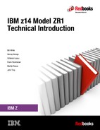
Internal, front, and rear views of the z14 ZR1 system with the maximum four PCIe+ I/O drawers are shown in Figure 2-2 on page 20.
Figure 2-2 z14 ZR1 front and rear views of a configuration with four PCIe+ I/O drawers
2.3 CPC drawer
A fully populated CPC drawer (for example, a Max24 or Max30) is shown in Figure 2-3. The z14 ZR1 features 672 MB of L4 cache. The Storage Controller (SC) chip provides X-Bus connectivity for PUS SCMs in a different logical cluster.

Figure 2-3 z14 ZR1 CPC drawer communication topology
The design that is used to connect the processor unit and SC allows the system to be operated and controlled by the IBM Processor Resource/Systems Manager™ (PR/SM™) facility as a memory-coherent symmetrical multiprocessor (SMP) system.
The z14 ZR1 features one CPC drawer that contains the following elements:
•Single chip modules:
– One, two, or four PU single chip modules, each containing five, six, seven, eight, or nine processor unit cores (air-cooled). For more information, see Table 2-1 on page 18.
– One System Controller single chip module, with a total of 672 MB L4 cache.
For more information about single chip modules, see 2.3.1, “Single chip modules” on page 21. For more information about available models and the relationship between the number of PU SCMs and number of available processor units, see Table 2-1 on page 18.
•Memory:
– A minimum of 64 GB and a maximum of 8 TB of memory (excluding 64 GB HSA) is available for client use. For more information, see Table 2-2 on page 24.
– A total of 5, 10, 15, or 20 memory DIMMs are plugged in a CPC drawer.
– The number of memory DIMMs that can be plugged into the CPC drawer depends on the CPC drawer feature.
•Fanouts
The CPC drawer provides up to eight PCIe Gen3 fanout adapters to connect to the PCIe+ I/O drawers and Integrated Coupling Adapter Short Reach (ICA SR) coupling links.
The number of fanouts that can be installed depends on the CPC drawer feature (see Table 2-2 on page 24).
The number of fanouts that can be installed depends on the CPC drawer feature (see Table 2-2 on page 24).
Each fanout can be one of the following configurations:
– A single port PCIe 16 GBps I/O fanout, each supporting one domain in a 16-slot PCIe+ I/O drawer.
– A dual port ICA SR PCIe fanout for coupling links (two links, 8 GBps each).
•Two or four Power Supply Units (PSUs) provide power to the CPC drawer and are accessible from the rear (depending on the number of PU SCMs that is installed).
Loss of one PSU leaves enough power to satisfy the power requirements of the entire drawer. The PSUs can be concurrently maintained.
•Two Flexible Support Processors (FSPs) provide redundant interfaces to the internal management network.
•Two Oscillator Cards (OSCs) provide clock synchronization to the CPC.
2.3.1 Single chip modules
The CPC drawer has up to four PU single chip modules (SCMs) and one SC SCM. Each PU SCM has five, six, seven, eight, or nine active PU cores, and L1, L2, and L3 caches. The SC SCM holds the L4 cache (672 MB).
For z14 ZR1, four CPC drawer configurations are offered with 8, 16, 28, and 34 active processor units.
The Storage Controller SCM includes 672 MB shared eDRAM cache, interface logic the four PU SCMs, and SMP fabric logic. The SC SMC is configured to provide a single 672 MB L4 cache that is shared by all PU cores in the CPC drawer.
2.3.2 Processor unit
Processor unit (PU) is the generic term for an IBM z/Architecture processor. Each PU is a superscalar processor with the following attributes:
•Up to six instructions can be decoded per clock cycle.
•Up to 10i instructions can be in execution per clock cycle.
•Instructions can be issued out of order. The PU uses a high-frequency, low-latency pipeline that provides robust performance across a wide range of workloads.
•Memory accesses might not be in the same instruction order (out-of-order operand fetching).
•Most instructions flow through a pipeline with varying numbers of steps for different types of instructions. Several instructions can be in execution at any moment, which are subject to the maximum number of decodes and completions per cycle.
PU cache
The on-chip cache for the PU (core) features the following design:
•Each PU core has an L1 cache (private) that is divided into a 128 KB cache for instructions and a 128 KB cache for data.
•Each PU core has a private L2 cache, with 4 MB D-cache (D for data) and 2 MB I-cache (I for instruction).
•Each PU SCM contains a 128 MB L3 cache that is shared by all PU cores in the SCM. The shared L3 cache uses eDRAM.
This on-chip cache implementation optimizes system performance for high-frequency processors, with cache improvements, new Translation/TLB2 design, pipeline optimizations, and better branch prediction.
The CPC drawer cache structure is shown in Figure 2-4.

Figure 2-4 z14 ZR1 cache structure
PU sparing
Hardware fault detection is embedded throughout the design and is combined with comprehensive instruction-level retry and dynamic PU sparing. This function provides the reliability and availability that is required for true mainframe integrity.
On-chip cryptographic hardware
Dedicated on-chip cryptographic hardware for each PU core includes extended key and hash sizes for the Advanced Encryption Standard (AES) and Secure Hash Algorithm (SHA), and support for UTF8 to UTF16 conversion. This cryptographic hardware is available with any processor type; for example, CP, IBM zIIP, and IFL.
Software support
The z14 ZR1 PUs provide full compatibility with software for z/Architecture, and extend the Instruction Set Architecture (ISA) to enable enhanced functionality and performance. The following hardware instructions support more efficient code generation and execution are introduced in the z14 ZR1:
•CP Assist for Cryptographic Functions (CPACF)
•Compression call (CMPSC)
•Hardware decimal floating point (HDFP)
•Transactional Execution Facility
•Runtime Instrumentation Facility
•Single-instruction, multiple-data (SIMD)
For more information about these capabilities, see Chapter 4, “Strengths of the z14 ZR1” on page 59.
PU characterization
PUs are ordered in single increments. The internal system functions are based on the configuration that is ordered. They characterize each PU into one of various types during system initialization, which is often called a power-on reset (POR) operation. Characterizing PUs dynamically without a POR is possible by using a process that is called Dynamic Processor Unit Reassignment. A PU that is not characterized cannot be used. Each PU can be designated by using one of the following characterizations:
•CP
•IFL processor
•zIIP
•ICF
•SAP
•IFP
At least one CP must be purchased with a zIIP or before a zIIP can be purchased. You can purchase up to two zIIPs for each purchased CP (assigned or unassigned) on the system.
However, an LPAR definition can go beyond the 1:2 ratio. For example, on a system with two physical CPs, a maximum of four physical zIIPs can be installed. An LPAR definition for that system can contain up to two logical CPs and four logical zIIPs. Another possible configuration is one logical CP and three logical zIIPs.
Converting a PU from one type to any other type is possible by using the Dynamic Processor Unit Reassignment process. These conversions occur concurrently with the system operation.
|
Note: The addition of ICFs, IFLs, zIIPs, and SAP to the z14 ZR1 does not change the system capacity setting or its million service units (MSU) rating.
|
2.3.3 Memory
The maximum physical memory size is directly related to the number of PU SCMs that is installed in the system. With the z14 ZR1, up to 8 TB of memory can be ordered.
|
Important: z/OS V2R3 requires a minimum of 8 GB of memory (2 GB of memory when running under z/VM). z/OS can support up to 4 TB of memory in an LPAR.
|
The minimum and maximum memory sizes for each z14 ZR1 feature are listed in Table 2-2.
Table 2-2 z14 ZR1 memory per feature
|
Feature name
|
PU SCMs
|
Memory
|
|
Max4 (FC 0636)
|
1
|
64 - 1984 GB
|
|
Max12 (FC 0637)
|
2
|
64 - 4032 GB
|
|
Max24 (FC 0638)
|
4
|
64 - 8128 GB
|
|
Max30 (FC 0639)
|
4
|
64 - 8128 GB
|
The hardware system area (HSA) on the z14 ZR1 features a fixed amount of memory (64 GB) that is managed separately from orderable memory. However, the maximum amount of orderable memory can vary from the theoretical number because of dependencies on the memory granularity. On z14 ZR1 platforms, the granularity for memory are in 8 GB, 32 GB, 64 GB, 128 GB, 256 GB, and 512 GB increments.
Physically, memory is organized in the following ways:
•The CPC drawer always contains a minimum of 128 GB of installed memory, of which 64 GB is usable by the operating system.
•The CPC drawer can have more installed memory than is enabled. The excess memory can be enabled by a Licensed Internal Code load.
•Memory upgrades are first satisfied by using installed but unused memory capacity until it is exhausted. When no more unused memory is available from the installed cards, cards must be added or the cards must be upgraded to a higher capacity.
A memory upgrade is considered to be concurrent when it requires no change of the physical memory cards. A memory card change is disruptive.
Concurrent memory upgrade
If physical memory is available, memory can be upgraded concurrently by using Licensed Internal Code Configuration Control (LICCC), as wanted. The plan ahead memory function that is available with the z14 ZR1 enables nondisruptive memory upgrades by having pre-plugged memory (based on a target configuration) in the system. Pre-plugged memory is enabled through an LICCC order that is placed by the client.
Redundant array of independent memory
RAIM technology makes the memory subsystem a fully fault-tolerant N+1 design in essence. The RAIM design automatically detects and recovers from failures of dynamic random access memory (DRAM), sockets, memory channels, or dual inline memory modules (DIMMs).
The RAIM design is fully integrated in the z14 ZR1 and was enhanced to include one Memory Controller Unit (MCU) per processor chip, with five memory channels and one DIMM per channel. A fifth channel in each MCU enables memory to be implemented as RAIM.
This technology has significant reliability, availability, and serviceability (RAS) capabilities in the area of error correction. Bit, lane, DRAM, DIMM, socket, and complete memory channel failures (including many types of multiple failures) can be detected and corrected.
For more information about memory design and configuration options, see IBM z14 Model ZR1 Technical Guide, SG24-8651.
2.3.4 Hardware system area
The HSA is a fixed-size, reserved area of memory that is separate from the purchased memory. Although the HSA is used for several internal functions, the bulk of it is used by channel subsystem functions.
The fixed-size 64 GB HSA for z14 ZR1 is large enough to accommodate any LPAR definitions or changes, which eliminates most outage situations and the need for extensive planning.
A fixed, large HSA allows the dynamic I/O capability of the z14 ZR1 to be enabled by default. It also enables the dynamic addition and removal of the following features:
•LPAR to new or existing channel subsystem (CSS)
•CSS (up to three can be defined in z14 ZR1)
•Subchannel set (up to three can be defined in z14 ZR1)
•Devices, up to the maximum number permitted, in each subchannel set
•Logical processors by type
•Cryptographic adapters
2.4 I/O system structure
The z14 ZR1 supports Generation 3 PCIe-based infrastructure for PCIe+ I/O drawers (PCIe Gen3). The number of supported PCIe+ I/O drawers is listed in Table 2-3.
Table 2-3 z14 ZR1 CPC drawer fanouts per feature
|
Feature name
|
PU SCMs
|
Max. PCIe fanouts
|
Max. PCIe+ I/O drawers1
|
|
Max4 (FC 0636)
|
1
|
2
|
1
|
|
Max12 (FC 0637)
|
2
|
4
|
2
|
|
Max24 (FC 0638)
|
4
|
8
|
4
|
|
Max30 (FC 0639)
|
4
|
8
|
4
|
1 If the 16U Reserved feature (FC 0617) is ordered, the maximum number of PCIe+ I/O drawers is two. For more information, see 2.4.1, “16U Reserved feature” on page 28.
The PCIe I/O infrastructure consists of PCIe Gen3 fanouts in the CPC drawer that support 16 GBps connectivity to the PCIe+ I/O drawer.
|
Note: Ordering I/O feature types and quantities determines the appropriate number of PCIe+ I/O drawers.
|
A high-level view of the connectivity between the CPC drawer and PCIe+ I/O drawer of the z14 ZR1 is shown in Figure 2-5.

Figure 2-5 z14 ZR1 connectivity of the I/O subsystem
The z14 ZR1 supports the following fanout types (for more information about fanout location, see Figure 2-6), which are at the front of the CPC drawer:
•ICA SR
•PCIe Gen3 (for PCIe+ I/O drawer)
The PCIe Gen3 fanout has one port; ICA SR has two ports.
For coupling link connectivity (parallel sysplex and STP configuration), the z14 ZR1 supports the following link types:
•ICA SR
•Coupling Express LR
The z14 ZR1 CPC drawer (see Figure 2-6 on page 27) can have up to eight 1-port PCIe Gen3 or 2-port ICA SR PCIe coupling fanouts (numbered LG01 - LG04 and LG07 - LG10). All coupling fanouts support parallel sysplex connectivity.

Figure 2-6 Front view of z14 ZR1 CPC drawer
The PCIe+ I/O drawer (see Figure 2-7) is a 19-inch single side drawer that is 8U high. I/O features are installed horizontally, with cooling air flow from front to rear. The drawer contains 16 slots and two switch cards. These features support two I/O domains that each contain eight features of any of the following types:
•FICON Express16S+, FICON Express16S, or FICON Express8S
•OSA-Express6S, OSA-Express5S, or OSA-Express4S
•Crypto Express6S or Crypto Express5S
•zEDC Express
•10GbE RoCE Express or 10GbE RoCE Express2
•zHyperLink Express
•Coupling Express LR

Figure 2-7 PCIe I/O drawer - front and rear views
Two PSUs provide redundant power, and six front-side fans provide redundant cooling to the PCIe+ I/O Drawer.
More information about the z14 ZR1 supported I/O features, see Chapter 3, “Supported features and functions” on page 31.
2.4.1 16U Reserved feature
IBM z14 ZR1 is a single 19-inch rack industry-standard footprint. In some cases, your installation might not require full four PCIe+ I/O drawer configuration.
If no more than two PCIe+ I/O drawers (eight EIA units each) are needed, the 19-inch rack has 16 EIA units contiguous rack space that is not populated with I/O. In addition, because no I/O is installed in those rack locations, no other power is available to the rack.
The 16U Reserved feature (FC 0617) uses the empty locations in the z14 ZR1 rack, which allows for maximizing data center space efficiency. The 16U Reserved feature tags 16U of contiguous rack space in the z14 ZR1 rack as “available” (in lieu of a third and fourth PCIe+ I/O drawer) for you to populate with your choice of equipment if it meets the documented specifications.
To stay within warranty boundaries of the z14 ZR1, the non-Z hardware content that is considered for installation must follow the following requirements (for more information, see the feature documentation):
•Fits within 19-inch rail-to-rail width, and 28 717-mm (1/4-inch) front-to-rear depth.
•Uses front to rear airflow.
•Features no more than 15.8 Kg (35 lbs.) weight per EIA location; for example, a 4U drawer can weigh no more than 65.5 Kg. (140 lbs.).
•Installed components show safety certification labels that are required for server components in the country where the system is used (such as UL or TUC).
•FC 0617 is ordered to reserve the space for planning and stay under warranty.
The maximum power that is reserved for this feature is 3400W.
For more information about the 16U Reserved rack space, see IBM 3907 Installation Manual for Physical Planning, CG28-6974.
The location of the 16U Reserved feature is shown in Figure 2-8.

Figure 2-8 16U Reserved feature location
2.5 Power and cooling
The z14 ZR1 meets the American Society of Heating, Refrigerating, and Air-Conditioning Engineers (ASHRAE) Class A3 specifications. (ASHRAE is an organization that is devoted to the advancement of indoor environment control technology in the heating, ventilation, and air conditioning industry.)
The air-cooling system in the z14 ZR1 is designed with N+1 blowers/fans, controls, and sensors for the CPC and PCIe+ I/O drawers.
The power and cooling system was redesigned for the IBM z14 ZR1 and includes the following features:
•To fit in a single 42U 19-inch IBM rack (replacing the 24-inch frame).
•Intelligent Power Distribution Units (PDUs) replace the Bulk Power Assemblies (BPAs):
– Two or four intelligent PDUs, depending on the machine configuration
– Single phase 200 - 240 VAC (two or four power cords)
•Air cooled (CPC and I/O): Front to rear air flow (all cabling in the rear, no cabling in front)
•No High-Voltage DC (HVDC) option or Internal Battery Feature (IBF)
•No Emergency Power Off switch (EPO)
•Uses single phase power as opposed to three-phase power
2.5.1 Power considerations
The z14 ZR1 has redundant PDUs, redundant PSUs for the CPC drawer, PCIe+ I/O drawers and Support Elements. The Ethernet switches are redundant and can be replaced with no effect on system operation. The loss of one PDU or one PSU also has no effect on system operation.
If the 16U Reserved feature is ordered, the power consumption and other considerations and restrictions for the non-Z equipment that is installed in the z14 ZR1 rack that might apply are described in IBM 3907 Installation Manual for Physical Planning, GC28-6974.
Specific power requirements depend on the CPC drawer features and the number and type of I/O units that are installed. For more information about the maximum power consumption for the various configurations and environments, see IBM 3907 Installation Manual for Physical Planning, GC28-6974.
For more information about the available power and weight estimation tool, see the IBM Resource Link® website.
1 The number of available PCIe fanout slots depends on the CPC drawer feature (Max4, Max12, Max24/Max30),
..................Content has been hidden....................
You can't read the all page of ebook, please click here login for view all page.