

Supported features and functions
This chapter describes the I/O and other miscellaneous features and functions of the z14. The information in this chapter expands upon the overview of the key hardware elements provided in Chapter 2, “IBM z14 hardware overview” on page 17. Only the enhanced features and functions introduced with the z14 are discussed more in detail. The remaining supported features from earlier generations of Z platforms are listed for convenience.
Throughout the chapter, reference is made to the IBM z14 Technical Guide, SG24-8451.
This chapter covers these topics:
3.1 I/O features at a glance
The z14 supports a PCIe-based infrastructure for PCIe I/O drawers to support these I/O features:
The following clustering and coupling links are support on the z14:
•Integrated Coupling Adapter - Short Reach (ICA SR)
•Host Channel Adapter3 - Optical Long Reach (HCA3-O LR)
•Host Channel Adapter3 - Optical (HCA3-O)
The following features that were part of earlier Z platforms are not orderable for the z14:
•ESCON
•FICON Express8 and older
•OSA-Express3 and older
•ISC-3
•Crypto Express4S and older
•Flash Express
Connector type LC Duplex is used for all fiber optic cables except those for the zHyperLink Express, HCA3-O (12x IFB), and ICA SR connections, which have multi-fiber push-on (MPO) connectors. The MPO connector of the HCA3-O (12x IFB) connection has one row of 12 fibers. The MPO connector of the zHyperLink Express and the ICA connection have two rows of 12 fibers, and are interchangeable.
The following pages list the supported features along with required cable types, maximum unrepeated distance, and bit rates. Tables for different purposes are provided and divided into the following sections:
Storage connectivity options are listed in Table 3-1. More detailed information about zHyperLink, FICON, and FCP connectivity in relation to the z14 can be found in 3.3, “Storage connectivity” on page 38.
Table 3-1 Storage connectivity features
|
Feature
|
Feature codes
|
Bit rate
in Gbps
(or stated)
|
Cable type
|
Maximum
unrepeated
distance
|
Ordering information
|
|
zHyperLink Express
|
0431
|
8 GBps
|
OM4, OM5
|
150 m
|
New build
|
|
OM3
|
100 m
|
||||
|
FICON Express16S+ 10KM LX
|
0427
|
4, 8, or 16
|
SM 9 µm
|
10 km
(6.2 miles) |
New build
|
|
FICON Express16S+ SX
|
0428
|
4, 8, or 16
|
OM2, OM3, and OM4
|
See Table 3-2
|
New build
|
|
FICON Express16S 10KM LX
|
0418
|
4, 8, or 16
|
SM 9 µm
|
10 km
(6.2 miles) |
Carry forward
|
|
FICON Express16S SX
|
0419
|
4, 8, or 16
|
OM2, OM3, and OM4
|
See Table 3-2
|
Carry forward
|
|
FICON Express8S 10KM LX
|
0409
|
2, 4, or 8
|
SM 9 µm
|
10 km
(6.2 miles) |
Carry forward
|
|
FICON Express8S SX
|
0410
|
2, 4, or 8
|
OM2, OM3, and OM4
|
See Table 3-2
|
Carry forward
|
Table 3-2 shows the maximum unrepeated distances for different multimode fiber optic cable types when used with FICON SX (shortwave) features running at different bit rates.
Table 3-2 Unrepeated distances for different multimode fiber optic cable types
|
Cable type
(Modal bandwidth)
|
2 Gbps
|
4 Gbps
|
8 Gbps
|
16 Gbps
|
|
OM1
(62.5 µm at 200 MHz·km)
|
150 meters
|
70 meters
|
21 meters
|
N/A
|
|
492 feet
|
230 feet
|
69 feet
|
N/A
|
|
|
OM2
(50 µm at 500 MHz·km)
|
300 meters
|
150 meters
|
50 meters
|
35 meters
|
|
984 feet
|
492 feet
|
164 feet
|
115 feet
|
|
|
OM3
(50 µm at 2000 MHz·km)
|
500 meters
|
380 meters
|
150 meters
|
100 meters
|
|
1640 feet
|
1247 feet
|
492 feet
|
328 feet
|
|
|
OM4
(50 µm at 4700 MHz·km)
|
N/A
|
400 meters
|
190 meters
|
125 meters
|
|
N/A
|
1312 feet
|
623 feet
|
410 feet
|
The network connectivity options are listed in Table 3-3. More detailed information about OSA-Express and RoCE Express connectivity in relation to the z14 can be found in 3.4, “Network connectivity” on page 42.
Table 3-3 Network connectivity features
|
Feature
|
Feature codes
|
Bit rate
in Gbps
(or stated)
|
Cable type
|
Maximum
unrepeated
distance1
|
Ordering information
|
|
OSA-Express6S 10 GbE LR
|
0424
|
10
|
SM 9 µm
|
10 km
(6.2 miles) |
New build
|
|
OSA-Express5S 10 GbE LR
|
0415
|
Carry forward
|
|||
|
OSA-Expess6S 10 GbE SR
|
0425
|
10
|
MM 62.5 µm
MM 50 µm
|
33 m (200)
82 m (500)
300 m (2000)
|
New build
|
|
OSA-Expess5S 10 GbE SR
|
0416
|
Carry forward
|
|||
|
OSA-Express6S GbE LX
|
0422
|
1.25
|
SM 9 µm
|
5 km
(3.1 miles) |
New build
|
|
OSA-Express5S GbE LX
|
0413
|
Carry forward
|
|||
|
OSA-Express6S GbE SX
|
0423
|
1.25
|
MM 62.5 µm
MM 50 µm
|
275 m (200)
550 m (500)
|
New build
|
|
OSA-Express5S GbE SX
|
0414
|
Carry forward
|
|||
|
OSA-Express6S 1000BASE-T
|
0426
|
100 or 1000 Mbps
|
Cat 5, Cat 6
unshielded twisted pair (UTP)
|
100 m
|
New build
|
|
OSA-Express5S 1000BASE-T
|
0417
|
Carry forward
|
|||
|
OSA-Express4S 1000BASE-T
|
0408
|
10, 100, or
1000 Mbps
|
|||
|
10GbE RoCE Express2
|
0412
|
10
|
MM 62.5 µm
MM 50 µm
|
33 m (200)
82 m (500)
300 m (2000)
|
New build
|
|
10GbE RoCE Express
|
0411
|
Carry forward
|
1 Where applicable, the minimum fiber bandwidth distance in MHz-km for multi-mode fiber optic links is included in parentheses.
Coupling link options are shown in Table 3-4. For more detailed information about the parallel sysplex or STP only link connectivity in relation to the z14, see 3.7, “Coupling and clustering” on page 51 and 3.9, “Server Time Protocol” on page 54.
Table 3-4 Coupling and clustering features
|
Feature
|
Feature codes
|
Bit rate
|
Cable type
|
Maximum
unrepeated
distance
|
Ordering information
|
|
CE LR
|
0433
|
10 Gbps
|
SM 9 µm
|
10 km
(6.2 miles) |
New build
|
|
ICA SR
|
0172
|
8 GBps
|
OM4
|
150 m
|
New build
or
Carry forward
|
|
OM3
|
100 m
|
||||
|
HCA3-O (12x IFB)
|
0171
|
6 GBps
|
OM3
|
150 m
|
Carry forward
|
|
HCA3-O LR (1x IFB)
|
0170
|
2.5 or
5 Gbps
|
SM 9 µm
|
10 km
(6.2 miles) |
|
|
Internal Coupling (IC)
|
No coupling link feature or fiber optic cable required
|
||||
Table 3-5 provides information about special purpose features like cryptographic or compression features, and Virtual Flash Memory. More information about the cryptographic features is provided in 3.6, “Cryptographic features” on page 49.
Table 3-5 Special-purpose features
|
Feature
|
Feature codes
|
Bit rate
in Gbps
|
Cable type
|
Maximum
unrepeated
distance
|
Ordering information
|
|
Crypto Express6S
|
0893
|
N/A
|
N/A
|
N/A
|
New build
|
|
Crypto Express5S
|
0890
|
N/A
|
N/A
|
N/A
|
Carry forward
|
|
zEDC Express
|
0420
|
N/A
|
N/A
|
N/A
|
New build or
Carry forward
|
|
Virtual Flash Memory
|
0604
|
N/A
|
N/A
|
N/A
|
New build
|
3.2 Native PCIe features and integrated firmware processor
The zEC12 introduced feature types, know as native PCIe features, that require a different management design compared to the other I/O features. The following native PCIe features are available on the z14:
•zHyperLink Express
•Coupling Express Long Reach (CE LR)
•10 Gigabit Ethernet (GbE) RoCE Express2
•10 Gigabit Ethernet (GbE) RoCE Express
•zEDC Express
These features are plugged exclusively into a PCIe I/O drawer, where they coexist with the other, non-native PCIe, I/O adapters, and features. However, they are managed in a different way from those other I/O adapters and features. The native PCle feature cards have a PCHID assigned according to the physical location in the PCIe I/O drawer.
For the native PCIe features supported by z14, drivers are included in the operating system, and the adaptation layer is not needed. The adapter management functions (such as diagnostics and firmware updates) are provided by Resource Groups partitions running on the integrated firmware processor (IFP). The z14 has four Resource Groups compared to two for the z13 and zEC12.
The IFP is used to manage native PCIe adapters installed in a PCIe I/O drawer. The IFP is allocated from a pool of processor units that are available for the whole system. Because the IFP is exclusively used to manage native PCIe adapters, it is not taken from the pool of processor units that can be characterized for customer usage.
If a native PCIe feature is present in the system, the IFP is initialized and allocated during the system POR phase. Although the IFP is allocated to one of the physical processor units, it is not visible. In case of error or failover scenarios, the IFP acts like any other processor unit (that is, sparing is started).
3.3 Storage connectivity
IBM is constantly investing in new and existing technologies to help their clients in investment protection and bring new values to them. In the storage connectivity area, the focus is on improving the latency for I/O transmission.
With the introduction of zHyperLink Express for the z14, IBM ensures the optimization of the Z I/O infrastructure.
In the FICON technology IBM introduced with the z14 the next generation of FICON features. This new FICON Express 16S+ feature is exclusive to the z14 and offers the same functions as its predecessor, the FICON Express16S feature, with increased performance.
For more information about FICON channel, see the Z I/O connectivity website. Technical papers about performance data are also available.
3.3.1 zHyperLink Express
IBM zHyperLink Express is a new, short distance, Z I/O adapter designed for up to 5x lower latency than High Performance FICON for read requests. This feature resides in the PCIe I/O drawer and is a two-port adapter used for short distance, direct connectivity between a z14 and a DS8880. It uses PCIe Gen3 technology, with x16 lanes that are bifurcated into x8 lanes for storage connectivity. The zHyperLink Express is designed to support distances up to 150 meters at a link data rate of 8 GigaBytes per second (GBps).
A 24x MTP-MTP cable is required for each port of the zHyperLink Express feature. It is single 24-fiber cable with Multi-fiber Termination Push-on (MTP) connectors. Internally, the single cable houses 12 fibers for transmit and 12 fibers for receive.
Note that FICON connectivity to each storage system is still required. The FICON connection is used for zHyperLink initialization, I/O requests that are not eligible for zHyperLink communications, and as an alternative path should zHyperLink requests fail (for example, storage cache misses or busy storage device conditions).
3.3.2 FICON functions
FICON features continue to evolve, delivering improved throughput, reliability, availability, and serviceability (RAS). FICON features in the z14 can provide connectivity to systems, Fibre Channel (FC) switches, and various devices in a SAN environment. The FICON protocol is fully supported on the z14. It is commonly used with IBM z/OS, IBM z/VM (and guest systems), IBM z/VSE, and IBM z/TPF. The next subsections describe the FICON enhancements.
FICON multi-hop and cascaded switch support
The z14 supports three hops (up to four FC switches) in a cascaded switch configuration. This support can help simplify the infrastructure with optimized RAS functionality. The support for a FICON multi-hop environment must also be provided by the FC switch vendor.
High Performance FICON for z Systems (zHPF)
High Performance FICON for z Systems (zHPF) is implemented for protocol simplification and efficiency, which it does by reducing the number of information units (IU) that are processed. Enhancements to the z/Architecture and the FICON protocol provide optimizations for online transaction processing (OLTP) workloads. zHPF can also be used by z/OS for IBM DB2, VSAM, PDSE, and zFS.
zHPF has been further enhanced to allow all large write operations greater than 64 KB to be run in a single round trip to the control unit at distances up to 100 km. This enhancement does not elongate the I/O service for these write operations at extended distances. It is especially useful for IBM GDPS HyperSwap configurations.
Additionally, the changes to the architecture provide end-to-end system enhancements to improve reliability, availability, and serviceability (RAS).
zHPF requires matching support by the IBM System Storage® DS8880 series or similar devices from other vendors. FICON Express16S+, FICON Express16S, and FICON Express8S support the FICON protocol and the zHPF protocol in the server Licensed Internal Code.
FICON Forward Error Correction
Even with proper fiber optic cable cleaning discipline, errors can still occur on 16 Gbps links. Forward Error Correction (FEC) is a technique used for controlling errors in data transmission over lower quality communication channels. With FEC, I/O errors are decreased, thus reducing potential impact on workload performance caused by I/O errors.
When running at 16 Gbps, FICON Express16S+ and FICON Express16S features can use FEC when connected to devices that support FEC, such as the IBM DS8880. FEC allows channels to operate at higher speeds, over longer distances, and with reduced power and higher throughput, while retaining the same reliability and robustness for which FICON channels have traditionally been known.
FICON Dynamic Routing
FICON Dynamic Routing (FIDR) is designed to support the dynamic routing policies supplied by FICON Director providers, such as Brocade’s Exchange Based Routing (EBR) and Cisco’s Open Exchange ID Routing (OxID).
With FIDR, you are no longer restricted to using static storage area network (SAN) routing policies for inter-switch links (ISLs) in a cascaded FICON Directors configuration. Performance of both FICON and FCP traffic improve due to SAN dynamic routing policies that better use all of the available ISL bandwidth through higher utilization.
The IBM DS8880 also supports FIDR, so in a configuration with the z14, capacity planning and management can be simplified, and provide persistent and repeatable performance and higher resiliency.
All devices in the SAN environment must support FICON Dynamic Routing to take advantage of this feature.
The z14s continue to provide the functions that were introduced on other Z platforms with the supported FICON features. For more information, see IBM Z Connectivity Handbook, SG24-5444.
3.3.3 FCP functions
Fibre Channel Protocol (FCP) is fully supported on the z14. It is commonly used with Linux on z Systems and supported by the z/VM and z/VSE. The next subsections describe the current FCP enhancements.
N_Port ID Virtualization
N_Port ID Virtualization (NPIV) is designed to allow the sharing of a single physical FCP channel among operating system images, whether in logical partitions or as z/VM guests. This goal is achieved by assigning a unique worldwide port name (WWPN) for each operating system that is connected to the FCP channel. In turn, each operating system appears to have its own distinct WWPN in the SAN environment, therefore enabling separation of the associated FCP traffic on the channel.
Access controls that are based on the assigned WWPN can be applied in the SAN environment. This function can be done by using standard mechanisms, such as zoning in SAN switches and logical unit number (LUN) masking in the storage controllers.
Several preferred and allowable operating characteristic values in the FCP protocol have increased:
•The preferred maximum number of NPIV hosts defined to any single physical FCP channel has increased from 32 to 64.
•The allowable maximum number of remote N_Ports a single physical channel can communicate with has increased from 512 to 1024.
•The maximum number of LUNs addressable by a single physical channel has increased from 4096 to 8192.
In support of these increases, the FCP channels have also been designed to now support 1528 concurrent I/O operations, an increase from the prior generation FCP channel limit of 764.
Export/import physical port WWPNs for FCP channels
IBM Z platforms automatically assign WWPNs to the physical ports of an FCP channel, and this WWPN assignment changes when an FCP channel is moved to a different physical slot position in the I/O drawer. The z14 allows for the modification of these default assignments, permitting FCP channels to keep previously assigned WWPNs. This capability eliminates the need for reconfiguration of the SAN environment when a Z platform upgrade occurs or when a FICON Express feature is replaced.
Fibre Channel Read Diagnostic Parameter
An extended link service (ELS) command called Read Diagnostic Parameter (RDP) has been added to the Fibre Channel T11 standard to allow Z platforms to obtain additional diagnostic data from the Small Form-factor Pluggable (SFP) optics located throughout the SAN fabric. RDP can identify a failed or failing component without unnecessarily replacing more components in the SAN fabric (such as FICON features, optics, cables, and so on).
FICON and FCP channels provide a means to read this additional diagnostic data for all of the ports accessed in the I/O configuration and make the data available to a Z LPAR. For FICON channels, z/OS displays the data with a message and display command. For Linux on z Systems, z/VM, z/VSE, and KVM for IBM z, this diagnostic data is made available in a window in the SAN Explorer tool on the Hardware Management Console (HMC).
3.3.4 FICON Express16S+
Two types of transceivers for FICON Express16S+ are supported on a new build system: One long wavelength (LX) laser version, and one short wavelength (SX) laser version:
•FICON Express16S+ LX feature
•FICON Express16S+ SX feature
Each port supports attachment to the following elements:
•FICON/FCP switches and directors that support 4 Gbps, 8 Gbps, or 16 Gbps
•Control units (storage subsystems) that support 4 Gbps, 8 Gbps, or 16 Gbps
|
Note: Both ports must be the same CHPID type, that is either FC or FCP
|
FICON Express16S+ LX feature
The FICON Express16S LX feature occupies one I/O slot in the PCIe I/O drawer. It has two ports, each supporting an LC duplex connector and auto-negotiated link speeds of 4 Gbps, 8 Gbps, and 16 Gbps up to an unrepeated maximum distance of 10 km.
FICON Express16S+ SX feature
The FICON Express16S SX feature occupies one I/O slot in the PCIe I/O drawer. It has two ports, each supporting an LC duplex connector and auto-negotiated link speeds of 4 Gbps, 8 Gbps, and 16 Gbps up to an unrepeated maximum distance1 of 380 meters at 4 Gbps, 150 meters at 8 Gbps, or 100 meters at 16 Gbps.
3.3.5 FICON Express16S (carry forward only)
Two types of transceivers for FICON Express16S are available only when carried forward on upgrades. Two types of transceivers for FICON Express16S are supported on z14:
•FICON Express16S LX feature
•FICON Express16S SX feature
Each port supports attachment to the following elements:
•FICON/FCP switches and directors that support 4 Gbps, 8 Gbps, or 16 Gbps
•Control units (storage subsystems) that support 4 Gbps, 8 Gbps, or 16 Gbps
|
Note: To permit the mix of different CHPID types (FC and FCP), the keyword MIXTYPE must be defined in the IODF to at least one port of the card.
|
FICON Express16S LX feature
The FICON Express16S LX feature occupies one I/O slot in the PCIe I/O drawer. It has two ports, each supporting an LC duplex connector and auto-negotiated link speeds of 4 Gbps, 8 Gbps, and 16 Gbps up to an unrepeated maximum distance of 10 km.
FICON Express16S SX feature
The FICON Express16S SX feature occupies one I/O slot in the PCIe I/O drawer. It has two ports, each supporting an LC duplex connector and auto-negotiated link speeds of 4 Gbps, 8 Gbps, and 16 Gbps up to an unrepeated maximum distance of 380 meters at 4 Gbps,
150 meters at 8 Gbps, or 100 meters at 16 Gbps.
150 meters at 8 Gbps, or 100 meters at 16 Gbps.
3.3.6 FICON Express8S (carry forward only)
The FICON Express8S features are available only when carried forward on upgrades. Two types of transceivers for FICON Express8 are supported on z14:
•FICON Express8S 10KM LX feature
•FICON Express8S SX feature
FICON Express8S 10KM LX feature
The FICON Express8S 10KM LX feature occupies one I/O slot in the I/O drawer. It has four ports, each supporting an LC duplex connector, and auto-negotiated link speeds of 2 Gbps, 4 Gbps, and 8 Gbps up to an unrepeated maximum distance of 10 km.
FICON Express8S SX feature
The FICON Express8S SX feature occupies one I/O slot in the I/O drawer. This feature has four ports, each supporting an LC duplex connector, and auto-negotiated link speeds of 2 Gbps, 4 Gbps, and 8 Gbps up to an unrepeated maximum distance of 500 meters at 2 Gbps, 380 meters at 4 Gbps, or 150 meters at 8 Gbps.
3.4 Network connectivity
The z14 offers a wide range of functions that can help consolidate or simplify the network environment. These include OSA-Express, RoCE-Express, and HiperSockets.
3.4.1 OSA-Express functions
Improved throughput (mixed inbound/outbound) is achieved by the data router function that was introduced in the OSA-Express3, and enhanced in OSA-Express6S and OSA-Express5S features. With the data router, the store and forward technique in DMA is no longer used. The data router enables a direct host memory-to-LAN flow. This function avoids a hop and is designed to reduce latency and to increase throughput for standard frames (1492 bytes) and jumbo frames (8992 bytes).
The following sections describe the most current OSA-Express functions.
OSM CHPID for usage with Dynamic Partition Manager
Dynamic Partition Manager (DPM) requires that the z14 has two OSA-Express5S 1000BASE-T Ethernet or OSA-Express6S 1000BASE-T Ethernet features defined as CHPID type OSM for connectivity. OSA-Express features defined with OSM cannot be shared with other CHPID types and must be dedicated for usage by DPM. DPM supports Linux for z Systems, running in an LPAR, under KVM hypervisor for IBM Z or z/VM 6.4.
DPM can be ordered along with Ensemble Membership, but they cannot both be enabled at the same time on the system.
OSA-ICC support for Secure Sockets Layer
The Open Systems Adapter, when configured as an integrated console controller CHPID type (OSC) on the z14, supports the configuration and enablement of secure connections using the Transport Layer Security (TLS) protocol versions 1.0, 1.1, and 1.2. Server-side authentication is supported using either a self-signed certificate or customer supplied certificate, which can be signed by a customer-specified certificate authority.
The certificates used must have an RSA key length of 2048 bits, and must be signed by using SHA-256. This support negotiates a cipher suite of AES-128 for the session key.
Queued direct I/O optimized latency mode
Queued direct I/O (QDIO) optimized latency mode can help improve performance for applications that have a critical requirement to minimize response times for inbound and outbound data. It optimizes the interrupt processing as noted in the following configurations:
•For inbound processing, the TCP/IP stack looks more frequently for available data to process, ensuring that any new data is read from the OSA-Express6S or OSA-Express5S without requiring more program-controlled interrupts.
•For outbound processing, the OSA-Express6S or OSA-Express5S looks more frequently for available data to process from the TCP/IP stack, thus not requiring a Signal Adapter instruction to determine whether more data is available.
Inbound workload queuing
Inbound workload queuing (IWQ) can help to reduce overhead and latency for inbound z/OS network data traffic and implement an efficient way for initiating parallel processing. This improvement is achieved by using OSA-Express features in QDIO mode (CHPID type OSD) with multiple input queues, and by processing network data traffic that is based on workload types. The data from a specific workload type is placed in one of four input queues (per device). A process is created and scheduled to run on one of the multiple processors, independent from the other three queues. This change can improve performance because IWQ can use the symmetric multiprocessor (SMP) architecture of the Z.
Virtual local area network support
Virtual local area network (VLAN) is a function of OSA-Express features that takes advantage of the Institute of Electrical and Electronics Engineers (IEEE) 802.q standard for virtual bridged LANs. VLANs allow easier administration of logical groups of stations that communicate as though they were on the same LAN. In the virtualized environment of the Z, TCP/IP stacks can exist, potentially sharing OSA-Express features. VLAN provides a greater degree of isolation by allowing contact with a server from only the set of stations that comprise the VLAN.
Virtual MAC support
When sharing OSA port addresses across LPARs, Virtual MAC (VMAC) support enables each operating system instance to have a unique VMAC address. All IP addresses associated with a TCP/IP stack are accessible by using their own VMAC address, instead of sharing the MAC address of the OSA port. Advantages can include a simplified configuration setup and improvements to IP workload load balancing and outbound routing.
This support is available for Layer 3 mode, is used by z/OS, and is supported by z/VM for guest use.
z/VM multi-VSwitch link aggregation support
z/VM V6.3 (with PTFs) or newer provides multi-VSwitch link aggregation support, allowing a port group of OSA-Express features to span multiple virtual switches within a single z/VM LPAR or between multiple z/VM LPARs. Sharing a link aggregation port group (LAG) with multiple virtual switches increases optimization and utilization of the OSA-Express when handling larger traffic loads. With this support, a port group is no longer required to be dedicated to a single z/VM virtual switch.
QDIO data connection isolation for the z/VM environment
New workloads increasingly require multitier security zones. In a virtualized environment, an essential requirement is to protect workloads from intrusion or exposure of data and processes from other workloads.
The QDIO data connection isolation enables the following elements:
•Adherence to security and HIPPA-security guidelines and regulations for network isolation between the instances that share physical network connectivity.
•Establishment of security zone boundaries that are defined by the network administrators.
•A mechanism to isolate a QDIO data connection (on an OSA port) by forcing traffic to flow to the external network. This feature ensures that all communication flows only between an operating system and the external network.
Internal routing can be disabled on a per-QDIO connection basis. This support does not affect the ability to share an OSA port. Sharing occurs as it does today, but the ability to communicate between sharing QDIO data connections can be restricted through this support.
QDIO data connection isolation (also known as VSWITCH port isolation) applies to the z/VM environment when using the Virtual Switch (VSWITCH) function, and to all supported OSA-Express features (CHPID type OSD) on Z. z/OS supports a similar capability.
QDIO interface isolation for z/OS
Some environments require strict controls for routing data traffic between servers or nodes. In certain cases, the LPAR-to-LPAR capability of a shared OSA port can prevent such controls from being enforced. With interface isolation, internal routing can be controlled on an LPAR basis. When interface isolation is enabled, the OSA discards any packets that are destined for a z/OS LPAR that is registered in the OAT as isolated.
QDIO interface isolation is supported by Communications Server for z/OS V1R11 and later, and for all supported OSA-Express features on Z.
3.4.2 OSA-Express6S
This section describes the connectivity options that are offered by the OSA-Express6S features. The following OSA-Express6S features can be installed on z14:
•OSA-Express6S 10 Gigabit Ethernet (GbE) Long Reach (LR)
•OSA-Express6S 10 Gigabit Ethernet (GbE) Short Reach (SR)
•OSA-Express6S Gigabit Ethernet Long Wavelength (GbE LX)
•OSA-Express6S Gigabit Ethernet Short Wavelength (GbE SX)
•OSA-Express6S 1000BASE-T Ethernet
OSA-Express6S 10 GbE LR feature
The OSA-Express6S 10 GbE LR feature occupies one slot in a PCIe I/O drawer. It has one port that connects to a 10 Gbps Ethernet LAN through a 9 µm single mode fiber optic cable that is terminated with an LC Duplex connector. The feature supports an unrepeated maximum distance of 10 km.
OSA-Express6S 10 GbE SR feature
The OSA-Express6S 10 GbE SR feature occupies one slot in the PCIe I/O drawer. This feature has one port that connects to a 10 Gbps Ethernet LAN through a 62.5 µm or 50 µm multimode fiber optic cable that is terminated with an LC Duplex connector.
The maximum supported unrepeated distance is 33 m on a 62.5 µm multimode fiber optic cable, and 300 m on a 50 µm multimode fiber optic cable.
OSA-Express6S GbE LX feature
The OSA-Express6S GbE LX occupies one slot in the PCIe I/O drawer. This feature has two ports, representing one channel path identifier (CHPID), that connect to a 1 Gbps Ethernet LAN through a 9 µm single mode fiber optic cable. This cable is terminated with an LC Duplex connector, supporting an unrepeated maximum distance of 5 km. A multimode (62.5 or 50 µm) fiber optic cable can be used with this feature. The use of these multimode cable types requires a Mode Conditioning Patch (MCP) cable at each end of the fiber optic link. Use of the single mode to multimode MCP cables reduces the supported distance of the link to a maximum of 550 meters.
OSA-Express6S GbE SX feature
The OSA-Express6S GbE SX occupies one slot in the PCIe I/O drawer. This feature has two ports, representing one CHPID, that connect to a 1 Gbps Ethernet LAN through 50 or 62.5 µm multimode fiber optic cable. This cable is terminated with an LC Duplex connector over an unrepeated distance of 550 meters (for 50 µm fiber) or 220 meters (for 62.5 µm fiber).
OSA-Express6S 1000BASE-T feature
The OSA-Express6S 1000BASE-T occupies one slot in the PCIe I/O drawer. It has two ports, representing one CHPID, that connect to a 1000 Mbps (1 Gbps) or 100 Mbps Ethernet LAN. Each port has an RJ-45 receptacle for UTP Cat5 or Cat6 cabling, which supports a maximum distance of 100 meters.
|
Note: The OSA-Express6S 1000BASE-T feature will be the last generation to support connections operating at 100 Mbps link speed. Future OSA-Express 1000BASE-T features will support operation only at 1 Gbps link speed.
|
3.4.3 OSA-Express5S (carry forward only)
This section describes the connectivity options that are offered by the OSA-Express5S features. The following OSA-Express5S features can be installed on z14:
•OSA-Express5S 10 Gigabit Ethernet (GbE) Long Reach (LR)
•OSA-Express5S 10 Gigabit Ethernet (GbE) Short Reach (SR)
•OSA-Express5S Gigabit Ethernet Long Wavelength (GbE LX)
•OSA-Express5S Gigabit Ethernet Short Wavelength (GbE SX)
•OSA-Express5S 1000BASE-T Ethernet
OSA-Express5S 10 GbE LR feature
The OSA-Express5S 10 GbE LR feature occupies one slot in a PCIe I/O drawer. It has one port that connects to a 10 Gbps Ethernet LAN through a 9 µm single mode fiber optic cable that is terminated with an LC Duplex connector. The feature supports an unrepeated maximum distance of 10 km.
OSA-Express5S 10 GbE SR feature
The OSA-Express5S 10 GbE SR feature occupies one slot in the PCIe I/O drawer. This feature has one port that connects to a 10 Gbps Ethernet LAN through a 62.5 µm or 50 µm multimode fiber optic cable that is terminated with an LC Duplex connector. The maximum supported unrepeated distance is 33 m on a 62.5 µm multimode fiber optic cable, and 300 m on a 50 µm multimode fiber optic cable.
OSA-Express5S GbE LX feature
The OSA-Express5S GbE LX occupies one slot in the PCIe I/O drawer. This feature has two ports, representing one CHPID, that connect to a 1 Gbps Ethernet LAN through a 9 µm single mode fiber optic cable. This cable is terminated with an LC Duplex connector, supporting an unrepeated maximum distance of 5 km. A multimode (62.5 or 50 µm) fiber optic cable can be used with this feature. The use of these multimode cable types requires a MCP cable at each end of the fiber optic link. Use of the single mode to multimode MCP cables reduces the supported distance of the link to a maximum of 550 meters.
OSA-Express5S GbE SX feature
The OSA-Express5S GbE SX occupies one slot in the PCIe I/O drawer. This feature has two ports, representing one CHPID, that connect to a 1 Gbps Ethernet LAN through 50 or 62.5 µm multimode fiber optic cable. This cable is terminated with an LC Duplex connector over an unrepeated distance of 550 meters (for 50 µm fiber) or 220 meters (for 62.5 µm fiber).
OSA-Express5S 1000BASE-T feature
The OSA-Express5S 1000BASE-T occupies one slot in the PCIe I/O drawer. It has two ports, representing one CHPID, that connect to a 1000 Mbps (1 Gbps) or 100 Mbps Ethernet LAN. Each port has an RJ-45 receptacle for UTP Cat5 or Cat6 cabling, which supports a maximum distance of 100 meters.
3.4.4 OSA-Express4S (carry forward only)
The OSA-Express4S features offer OSA-Express4S 1000BASE-T Ethernet connectivity options on a z14.
OSA-Express4S 1000BASE-T feature
The OSA-Express4S 1000BASE-T occupies one slot in the PCIe I/O drawer. It has two ports, representing one CHPID, that connect to a 1000 Mbps (1 Gbps), 100 Mbps, or 10 Mbps Ethernet LAN. Each port has an RJ-45 receptacle for UTP Cat5 or Cat6 cabling, which supports a maximum distance of 100 meters.
3.4.5 HiperSockets functions
IBM HiperSockets has been referred to as the “network in a box” because it simulates LAN environments entirely in the hardware. The data transfer is from LPAR memory to LPAR memory, mediated by microcode. The z14 support up to 32 HiperSockets. One HiperSockets network can be shared by up to 85 LPARs. Up to 4096 communication paths support a total of 12,288 IP addresses across all 32 HiperSockets.
The HiperSockets internal networks can support the following transport modes:
•Layer 2 (link layer)
•Layer 3 (network or IP layer)
Traffic can be Internet Protocol Version 4 or Version 6 (IPv4, IPv6) or non-IP (such as AppleTalk, DECnet, IPX, NetBIOS, SNA, or others). HiperSockets devices are independent of protocol and Layer 3. Each HiperSockets device has its own Layer 2 Media Access Control (MAC) address. This address is designed to allow the use of applications that depend on the existence of Layer 2 addresses such as Dynamic Host Configuration Protocol (DHCP) servers and firewalls.
Layer 2 support can help facilitate server consolidation. Complexity can be reduced, network configuration is simplified and intuitive, and LAN administrators can configure and maintain the mainframe environment the same way as they do for a non-mainframe environment. HiperSockets Layer 2 support is provided by Linux on z Systems, and by z/VM for guest use.
The most current HiperSockets functions are described in the following sections.
HiperSockets Multiple Write Facility
HiperSockets performance is enhanced to allow for the streaming of bulk data over a HiperSockets link between LPARs. The receiving LPAR can now process a much larger amount of data per I/O interrupt. This enhancement is transparent to the operating system in the receiving LPAR. HiperSockets Multiple Write Facility, with fewer I/O interrupts, reduces CPU use of the sending and receiving LPAR. The HiperSockets Multiple Write Facility is supported in the z/OS environment.
zIIP-Assisted HiperSockets for large messages
In z/OS, HiperSockets are enhanced for zIIP usage. Specifically, the z/OS Communications Server allows the HiperSockets Multiple Write Facility processing for outbound large messages that originate from z/OS to be performed on a zIIP.
zIIP-Assisted HiperSockets can help make highly secure and available HiperSockets networking an even more attractive option. z/OS application workloads that are based on XML, HTTP, SOAP, Java, and traditional file transfer can benefit from zIIP enablement by lowering general-purpose processor use for such TCP/IP traffic.
When the workload is eligible, the TCP/IP HiperSockets device driver layer (write) processing is redirected to a zIIP, which unblocks the sending application.
HiperSockets network traffic analyzer
HiperSockets network traffic analyzer (NTA) is a function that is available in the LIC of
z Systems. It can simplify problem isolation and resolution by allowing Layer 2 and Layer 3 tracing of HiperSockets network traffic.
z Systems. It can simplify problem isolation and resolution by allowing Layer 2 and Layer 3 tracing of HiperSockets network traffic.
HiperSockets NTA allows Linux on z Systems to control tracing of the internal virtual LAN. It captures records into host memory and storage (file systems) that can be analyzed by system programmers and network administrators. These administrators can use Linux on z Systems tools to format, edit, and process the trace records.
A customized HiperSockets NTA rule enables authorizing an LPAR to trace messages only from LPARs that are eligible to be traced by the NTA on the selected IQD channel.
HiperSockets completion queue
The HiperSockets completion queue function allows both synchronous and asynchronous transfer of data between logical partitions. With the asynchronous support, during high volume situations, data can be temporarily held until the receiver has buffers available in its inbound queue. This function can provide performance improvement for LPAR to LPAR communication, and can be especially helpful in burst situations.
HiperSockets virtual switch bridge support
The z/VM virtual switch is enhanced to transparently bridge a guest virtual machine network connection on a HiperSockets LAN segment. This bridge allows a single HiperSockets guest virtual machine network connection to also directly communicate with the following systems:
•Other guest virtual machines on the virtual switch
•External network hosts through the virtual switch OSA UPLINK port
A HiperSockets channel by itself is only capable of providing intra-CPC communications. The HiperSockets Bridge Port allows a virtual switch to connect z/VM guests by using real HiperSockets devices, the ability to communicate with hosts that reside externally to the CPC. The virtual switch HiperSockets Bridge Port eliminates the need to configure a separate next hop router on the HiperSockets channel to provide connectivity to destinations that are outside of a HiperSockets channel.
3.4.6 Shared Memory Communications functions
The Shared Memory Communication (SMC) capabilities of the z14 optimizes the communications between applications in server-to-server (SMC-R) or LPAR-to-LPAR (SMC-D) connectivity.
SMC-R provides application transparent exploitation of the RoCE-Express feature that reduces the network overhead and latency of data transfers, effectively offering the benefits of optimized network performance across processors.
The Internal Shared Memory (ISM) virtual PCI function takes advantage of the capabilities of SMC-D. ISM is a virtual PCI network adapter that enables direct access to shared virtual memory, providing a highly optimized network interconnect for Z intra-system communications. Up to 32 channels for SMC-D traffic can be defined in a z14, whereby each channel can be virtualized to a maximum of 255 Function IDs2.
3.4.7 10 Gigabit Ethernet RoCE Express features
This section describes the connectivity options that are offered by the Remote Direct Memory Access (RDMA) over Converged Ethernet (RoCE) Express features. The following RoCE features can be installed on z14:
•10 Gigabit Ethernet (GbE) RoCE Express2
•10 Gigabit Ethernet (GbE) RoCE Express (carry forward only)
The 10 Gigabit Ethernet (10GbE) RoCE Express feature helps reduce consumption of CPU resources for applications that use the TCP/IP stack, and might also help to reduce network latency with memory-to-memory transfers using SMC-R in z/OS V2R1 and later versions. It is transparent to applications, and can be used for server-to-server communication in a multiple Z platform environment.
This feature resides in the PCIe I/O drawer and is available to the z14. The 10GbE RoCE Express features have one PCIe adapter with two ports.
The 10GbE RoCE Express feature uses a short reach (SR) laser as the optical transceiver, and supports use of a multi-mode fiber optic cable terminated with an LC Duplex connector. Both point-to-point connection and switched connection with an enterprise-class 10 GbE switch are supported. Switches used by the 10GbE RoCE Express feature must have the Pause frame enabled as defined by the IEEE 802.3x standard.
A maximum of eight features (any combination of 10GbE RoCE Express2 or 10GbE RoCE Express features) can be installed in the z14.
10 Gigabit Ethernet (GbE) RoCE Express2 (carry forward only)
The 10 Gigabit Ethernet (GbE) RoCE Express2 feature occupies one slot in the PCIe I/O drawer. This feature has two ports that connect to a 10 Gbps Ethernet LAN through a 62.5 µm or 50 µm multimode fiber optic cable that is terminated with an LC Duplex connector. The maximum supported unrepeated distance is 300 m on an OM3 multimode fiber optic cable, and can be increased to 600 m when sharing a switch across two 10 GbE RoCE Express2 features. The 10GbE RoCE Express2 supports 63 Virtual Functions (VFs)3 per physical port.
10 Gigabit Ethernet (GbE) RoCE Express (carry forward only)
The 10 Gigabit Ethernet (GbE) RoCE Express feature occupies one slot in the PCIe I/O drawer. This feature has two ports that connect to a 10 Gbps Ethernet LAN through a 62.5 µm or 50 µm multimode fiber optic cable that is terminated with an LC Duplex connector. The maximum supported unrepeated distance is 300 m on an OM3 multimode fiber optic cable, and can be increased to 600 m when sharing a switch across two RoCE Express features. The RoCE Express supports 31 VFs per feature.
3.5 Compression options
Two types of compression options are available with the z14: A standard internal compression coprocessor tightly connected to each processor unit, and an external native PCIe feature.
3.5.1 Compression Coprocessor
The Compression Coprocessor (CMPSC) is a well known feature that works in tight conjunction with the processor units in the Z. This coprocessor works with a proprietary compression format and is used for many types of z/OS data.
3.5.2 zEnterprise Data Compression
zEnterprise Data Compression (zEDC) Express is an optional native PCIe feature that is available in the z14. It provides hardware-based acceleration for data compression and decompression for the enterprise, which can help to improve cross platform data exchange, reduce CPU consumption, and save disk space.
A minimum of one feature can be ordered and a maximum of eight can be installed on the system, in the PCIe I/O drawer. Up to two zEDC Express features per domain can be installed. There is one PCIe adapter/compression processor per feature that implements compression as defined by RFC1951 (DEFLATE). A zEDC Express feature can be shared between up to 31 LPARs.
3.6 Cryptographic features
The z14 provide cryptographic functions that, from an application program perspective, can be grouped as follows:
•Synchronous cryptographic functions, provided by the CP Assist for Cryptographic Function (CPACF) or the Crypto Express features when defined as an accelerator.
•Asynchronous cryptographic functions, provided by the Crypto Express features.
3.6.1 CP Assist for Cryptographic Function
CPACF offers a set of symmetric cryptographic functions for high-performance encryption and decryption with clear key operations for SSL/TLS, VPN, and data-storing applications that do not require FIPS 140-2 level 4 security4 . The CPACF is an optional feature that is integrated with the compression unit in the coprocessor in the z14 microprocessor core.
The CPACF protected key is a function that facilitates the continued privacy of cryptographic key material while keeping the wanted high performance. CPACF ensures that key material is not visible to applications or operating systems during encryption operations. CPACF protected key provides substantial throughput improvements for large-volume data encryption and low latency for encryption of small blocks of data.
The cryptographic assist includes support for the following functions:
•Advanced Encryption Standard (AES) for 128-bit, 192-bit, and 256-bit keys
•Data Encryption Standard (DES) data encryption and decryption with single, double, or triple length keys.
•Pseudo-random number generation (PRNG)
•Message authentication code (MAC)
•Hashing algorithms: SHA-1, SHA-2, and SHA-3
SHA-1, SHA-2, and SHA-3 support are enabled on all Z platforms and do not require the CPACF enablement feature. The CPACF functions are supported by z/OS, z/VM, z/VSE, z/TPF, and Linux on z Systems.
See “Pervasive encryption” on page 82 regarding use of this function.
3.6.2 Crypto Express6S
The Crypto Express6S represents the newest generation of the Peripheral Component Interconnect Express (PCIe) cryptographic coprocessors, an optional feature exclusive to the z14. These are Hardware Security Modules (HSMs) designed to provide high-security cryptographic processing as required by banking and other industries. This feature provides a secure programming and hardware environment wherein crypto processes are performed. Each cryptographic coprocessor includes general-purpose processors, non-volatile storage, and specialized cryptographic electronics, all contained within a tamper-sensing and tamper-responsive enclosure which destroys all keys and sensitive data on any attempt to tamper with the device. The security features of the HSM are designed to meet the requirements of FIPS 140-2, Level 4, the highest security level defined.
The Crypto Express6S has one PCIe adapter per feature. For availability reasons, a minimum of two features is required. Up to 16 Crypto Express6S features are supported. The Crypto Express6S feature occupies one I/O slot in a PCIe I/O drawer.
Each adapter can be configured as a Secure IBM CCA coprocessor, a Secure IBM Enterprise PKCS #11 (EP11) coprocessor, or as an accelerator.
Crypto Express6S provides domain support for up to 85 logical partitions.
The accelerator function is designed for maximum-speed Secure Sockets Layer and Transport Layer Security (SSL/TLS) acceleration, rather than for specialized financial applications for secure, long-term storage of keys or secrets. The Crypto Express6S can also be configured as one of the following configurations:
•The Secure IBM CCA coprocessor includes secure key functions with emphasis on the specialized functions required for banking and payment card systems. It is optionally programmable to add custom functions and algorithms by using User Defined Extensions (UDX).
– A new mode, called Payment Card Industry (PCI) PIN Transaction Security (PTS) Hardware Security Module (HSM), shortened to PCI-HSM, is available exclusively for Crypto Express6S in CCA mode. PCI-HSM mode simplifies compliance with PCI requirements for hardware security modules.
•The Secure IBM Enterprise PKCS #11 (EP11) coprocessor implements an industry-standardized set of services that adheres to the PKCS #11 specification v2.20 and more recent amendments. It was designed for extended FIPS and Common Criteria evaluations to meet industry requirements.
This cryptographic coprocessor mode introduced the PKCS #11 secure key function.
|
TKE feature: The Trusted Key Entry (TKE) Workstation feature is required for supporting the administration of the Crypto Express6S when configured as an Enterprise PKCS #11 coprocessor or managing the new CCA mode PCI-HSM.
|
When the Crypto Express6S PCI Express adapter is configured as a secure IBM CCA co-processor, it still provides accelerator functions. However, up to three times better performance for those functions can be achieved if the Crypto Express6S PCI Express adapter is configured as an accelerator.
3.6.3 Crypto Express5S (carry forward only)
The Crypto Express5S has one PCIe adapter per feature. For availability reasons, a minimum of two features is required. Up to 16 Crypto Express5S features are supported. The Crypto Express5S feature occupies one I/O slot in a PCIe I/O drawer.
Each adapter can be configured as a Secure IBM CCA coprocessor, a Secure IBM Enterprise PKCS #11 (EP11) coprocessor, or as an accelerator.
Crypto Express5S provides domain support for up to 85 logical partitions on IBM z13 and 40 logical partitions on z13s.
The Crypto Express5S feature supports all the functions of the Crypto Express6S, except the PCI-HSM standard.
3.6.4 Web deliverables
3.7 Coupling and clustering
Coupling connectivity for Parallel Sysplex on z14 use Coupling Express Long Reach (CE LR), Integrated Coupling Adapter Short Reach (ICA SR), and InfiniBand (IFB) technology. The ICA SR and HCA3-O SR are designed to support distances up to 150 m. The CE LR and HCA3-O LR fanout supports longer distances between systems.
CE LR, ICA SR, and InfiniBand technologies allow all of the z/OS-to-CF communication, CF-to-CF traffic, or Server Time Protocol (STP)5 through high-speed fiber optic connections at short (up to 150 m) or long (up to 10 km unrepeated) distances.
See the Coupling Facility Configuration Options white paper for a more specific explanation regarding the coupling links technologies.
|
Note: The z14 will be the last Z platform to support InfiniBand coupling connectivity (SOD: Hardware Announcement 117-031).
|
3.7.1 Coupling Express Long Reach
The CE LR, first introduced on the z14 platform but also made available on IBM z13 and IBM z13s™, is a two-port PCIe native adapter that is used for long-distance coupling connectivity. CE LR uses a new coupling channel type: CL5. The CE LR feature uses PCIe Gen3 technology and is hosted in a PCIe I/O drawer.
The feature supports communication at unrepeated distances up to 10 km (6.2 miles) using 9 µm single-mode fiber optic cables and repeated distances up to 100 km (62 miles) using IBM Z qualified DWDM vendor equipment. It supports up to 4 CHPIDs per port and 8 or 32 subchannels (devices) per CHPID. The coupling links can be defined as shared between images within a CSS or spanned across multiple CSSs in a Z system.
3.7.2 Integrated Coupling Adapter: Short Reach
ICA SR, first introduced on the z13 platform, is a two-port fanout used for short distance coupling connectivity and uses the coupling channel type CS5. The ICA uses PCIe Gen3 technology, with x16 lanes that are bifurcated into x8 lanes for coupling.
The ICA SR supports cable length of up to 150 m and supports a link data rate of 8 GBps. It also supports up to four CHPIDs per port and 8 subchannels (devices) per CHPID. The coupling links can be defined as shared between images within a CSS. They can also be spanned across multiple CSSs in a Z system.
3.7.3 Host Channel Adapter3: Optical Long Reach
HCA3-O LR is a fanout card, based on InfiniBand protocol, that supports 1x InfiniBand (1x IFB). The HCA3-O LR fanout for 1x InfiniBand (1x IFB) provides four ports and optional additional subchannels for extended-distance solutions.
The HCA3-O LR 1x InfiniBand supports up to 16 CHPIDs. The CHPID type is CIB and up to 7 or 32 subchannels (devices) are supported.
InfiniBand (HCA3-O LR) coupling links support unrepeated distances up to 10 km (6.2 miles) using 9 µm single mode fiber optic cables and repeated distances up to 100 km (62 miles) using IBM Z qualified DWDM equipment. Connectivity to HCA2-O LR on older Z platforms is supported.
3.7.4 Host Channel Adapter3: Optical
HCA3-O is a fanout card, based on InfiniBand protocol, that supports 12x InfiniBand (12x IFB). The HCA3-O fanout for 12x InfiniBand (12x IFB) provides two ports and optional additional subchannels.
The 12x InfiniBand coupling links support double data rate (DDR) at 6 GBps for a z14 to z14 or other supported Z platforms.
InfiniBand (HCA3-O) coupling links (12x IFB) support distances up to 150 meters (492 feet) by using industry standard OM3 50 µm fiber optic cables. An HCA3-O to HCA2-O connection is supported.
3.7.5 Internal coupling
Internal coupling (IC) links are used for internal communication between LPARs on the same system running coupling facilities (CF) and z/OS images. The connection is emulated in Licensed Internal Code (LIC) and provides for fast and secure memory-to-memory communications between LPARs within a single system. No physical cabling is required.
3.7.6 Coupling Facility Control Code Level 22
Various levels of Coupling Facility Control Code (CFCC) are available. CFCC Level 22 is available on z14 with driver level 32, and includes the following enhancements:
•Support for up to 170 ICF processors
The maximum number of logical processors in a Coupling Facility Partition remains at 16.
•Scalability enhancement:
Coupling Facility work management and dispatcher changes to allow improved efficiency as additional processors are added to scale up the capacity of a CF image:
– Non-prioritized (FIFO-based) work queues.
– Simplified system-managed duplexing protocol.
– Specialized use of processors when the number of dedicated processors in the CF image exceeds a threshold.
•CF list notification enhancements
CF list structures support three notification mechanisms to inform exploiters about the status of shared objects in the CF:
– List (used by many exploiters including XCF Signaling).
– Key-range (used predominantly by WebSphere MQ shared queues).
– Sublist notification (used predominantly by IMS shared queues).
The following three enhancements to these existing notification mechanisms will be provided:
– Immediate/delayed round-robin notification for list and key-range notifications.
– Additional notifications to be sent to users as extra work elements are placed onto list or key-range (controlled by using the API).
– List full/not-full notifications.
CF structure size changes are expected to grow when going from CFCC Level 21 (or earlier) to CFCC Level 22. Review the CF LPAR size by using the following tools:
•The CFSizer tool is a web-based and is useful when changing an existing workload or introducing a new one.
•The Sizer Utility, an authorized z/OS program download, is useful when upgrading a CF.
3.8 Virtual Flash Memory
IBM Virtual Flash Memory (VFM) is the replacement for the Flash Express features that were available on the z13 and zEC12. VFM can be ordered in 1.5 TB increments up to 6 TB in total.
VFM is designed to help improve availability and handling of paging workload spikes when running z/OS V2.1, V2.2, or V2.3. With this support, z/OS is designed to help improve system availability and responsiveness by using VFM across transitional workload events such as market openings, and diagnostic data collection. z/OS is also designed to help improve processor performance by supporting middleware exploitation of pageable large (1 MB) pages.
VFM can also be used in coupling facility images to provide extended capacity and availability for workloads that use WebSphere MQ Shared Queues structures. Using VFM can help availability by reducing latency from paging delays that can occur at the start of the workday or during other transitional periods. It is also designed to eliminate delays that can occur when collecting diagnostic data during failures.
Therefore, VFM can help meet most demanding service level agreements and compete more effectively. VFM is easy to configure and provides rapid time to value.
No application changes are required to migrate from IBM Flash Express to VFM.
3.9 Server Time Protocol
Each system must have an accurate time source to maintain a time-of-day value. Logical partitions use their system’s time. When system images participate in a Sysplex, coordinating the time across all system images in the sysplex is critical to its operation.
The z14 supports the Server Time Protocol (STP) and can participate in a STP-only Coordinated Timing Network (CTN). A CTN is a collection of Z platforms that are time-synchronized to a time value called Coordinated Server Time (CST). Each CPC to be configured in a CTN must be STP-enabled. STP is intended for CPCs that are configured to participate in a Parallel Sysplex or CPCs that are not in a Parallel Sysplex, but must be time-synchronized.
STP is a message-based protocol in which timekeeping information is passed over coupling links between servers. The timekeeping information is transmitted over externally defined coupling links. The STP feature is the supported method for maintaining time synchronization between the z14 and coupling facilities (CF) in sysplex environments.
STP is implemented in LIC as a system-wide facility of the z14 and other Z platforms. STP presents a single view of time to PR/SM and provides the capability for multiple CPCs to maintain time synchronization with each other. The z14 is enabled for STP by installing the STP feature code. Extra configuration is required for a z14 to become a member of a CTN.
STP supports a multi-site timing network of up to 100 km (62 miles) over fiber optic cabling, without requiring an intermediate site. This protocol allows a Parallel Sysplex to span these distances and reduces the cross-site connectivity that is required for a multi-site Parallel Sysplex.
Network Time Protocol client support
The use of Network Time Protocol (NTP) servers as an External Time Source (ETS) usually fulfills a requirement for a time source or common time reference across heterogeneous platforms and for providing a higher time accuracy.
NTP client support is available in the Support Element (SE) code of the z14. The code interfaces with the NTP servers. This interaction allows an NTP server to become the single-time source for z14 and for other servers that have NTP clients.
Pulse per second support
Two oscillator cards (OSCs), included as a standard feature of the z14 provide a dual-path interface for the pulse per second (PPS) signal. The cards contain a BNC connector for PPS attachment at the rear side of Frame A of the Z platform. The redundant design allows continuous operation during the failure of one card, and concurrent card maintenance.
STP tracks the highly stable accurate PPS signal from the NTP server. PPS maintains accuracy of 10 µs as measured at the PPS input of the z14.
If STP uses an NTP server without PPS, a time accuracy of 100 ms to the ETS is maintained. A cable connection from the PPS port to the PPS output of an NTP server is required when the z14 is configured for using NTP with PPS as the ETS for time synchronization.
For more information about STP, see the following books:
3.10 Hardware Management Console functions
The HMC and Support Element (SE) are appliances that provide Z hardware platform management. Hardware platform management covers a complex set of setup, configuration, operation, monitoring, and service management tasks, and services that are essential to the use of the Z platform.
When tasks are performed on the HMC, the commands are sent to one or more SEs, which issue commands to their Z platforms.
HMC/SE Version 2.14.0 or later is required for the z14. For more information about these HMC functions and capabilities, see the IBM z14 Technical Guide, SG24-8451.
3.10.1 HMC key enhancements for z14
The HMC application has several enhancements:
•The User Interface has been redesigned and simplified.
•Tasks and windows were updated to support configuring and managing STP, IBM Virtual Flash Memory, IBM Secure Service Container, and 10GbE RoCE Express features.
•OSA/SF was migrated from z/OS environment to HMC on the z13. With z14 server OSA/SF has additional monitoring and diagnostic capabilities.
•A new set of Trusted Computing features is implemented for tampering protection like BIOS Secure boot function, signature and verification for HMCs firmware, and more.
•Starting with version 2.13.1 HMC Tasks no longer have Java Applets based implementations. Java Applets were used in Operating System Messages, Version 2.14.0 implements new IOCDS Source option on input/output configuration tasks.
•FTP, FTPS, and SFTP are supported. All FTP connections originating from Support Element are taken by HMC and performed on behalf of FTP.
•Secure console-to-console communication was established for z14 HMC consoles putting new security standards on internal communication.
•There are functional enhancements in SNMP/BCPii API interfaces such as queries to Virtual Flash Memory or queries to Secure Service Container. Security of BCPii interface was also enhanced.
•Remote Browser IP Address Limiting function was implemented due to security reasons. This function allows you to specify valid remote browser IP or valid mask for group of IP addresses. Global setting to enable/disable remote access is still available.
•Multi-factor authentication was implemented for z14 HMC/SE/TKE. The feature enables you to log in with higher security level using two factors. The first factor is traditional login and password, and the second factor is a passcode sent on your smartphone.
•The HMC Global OSA/SF now provides a global view of all OSA PCHIDs and the monitoring and diagnostic information previously available in the Query Host command.
•The PCI HSM specification defines a set of logical and physical security standards for HSMs specific to the needs of payments industry.
•Compliance mode for CCA PCI-HSM and EP11 and other certificates is now displayed on Support Element. Setup and administration tasks are done on TKE.
•A new Mobile application interface is provided for the HMC 2.14.0, which includes security technology.
For more information about the key capabilities and enhancements of the HMC, see IBM z14 Technical Guide, SG24-8451.
3.10.2 Hardware Management Console and Support Element
The HMC and SE appliances together provide hardware platform management for IBM Z. Hardware platform management covers a complex set of configuration, operation, monitoring, service management tasks, and other services that are essential to the use of the hardware platform product.
With z14, the HMC can be a stand-alone desktop computer or an optional 1U rack-mounted computer.
The z14 is supplied with a pair of integrated 1U SEs. One, the primary SE, is always active, and the other is an alternate. Power for the SEs is supplied by the Z platform’s power supply, and there are no additional power requirements. The SEs are connected to the external customer switches for network connectivity with the CPC and the HMCs.
The SEs and HMCs are closed systems, and no other applications can be installed on them.
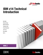
The HMCs and SEs of the system are attached to a Customer LAN. An HMC communicates with one or more Z platform, as shown in Figure 3-1 on page 57. When tasks are performed on the HMC, the commands are sent to one or more SEs, which then issue commands to their CPCs.
The HMC Remote Support Facility (RSF) provides communication with the IBM support network for hardware problem reporting and service.
Figure 3-1 shows an example of the HMC and SE connectivity.
|
RSF connection: RSF connection through a modem is not supported on the z14 HMC. An Internet connection to IBM is required to have hardware problem reporting and service.
|

Figure 3-1 HMC and SE connectivity
1 Distances are valid for OM3 cabling. See Table 3-5 on page 37 for more options.
2 The 10GbE RoCE features and the ISM adapters are identified by a hexadecimal Function Identifier (FID) with a range of 00 - FF.
3 Virtual Function ID is defined when PCIe hardware or the ISM is shared between LPARs.
4 Federal Information Processing Standards (FIPS) 140-2 Security Requirements for Cryptographic Modules
5 All coupling links can be used to carry STP timekeeping information.
..................Content has been hidden....................
You can't read the all page of ebook, please click here login for view all page.