
Chapter 12. FlexVPN Deployments
Introduction
This chapter covers the various FlexVPN deployment scenarios, based on the FlexVPN features explained in the previous chapters. The FlexVPN features were developed to simplify the deployments and address the scalability and the various resiliency requirements. This chapter provides sample configurations and verification steps for some of these deployment scenarios.
The chapter covers the following scenarios:
![]() FlexVPN AAA-based pre-shared keys
FlexVPN AAA-based pre-shared keys
![]() FlexVPN user and group authorization
FlexVPN user and group authorization
![]() FlexVPN routing, dual stack, and tunnel mode auto
FlexVPN routing, dual stack, and tunnel mode auto
![]() FlexVPN client NAT to server-assigned IP address
FlexVPN client NAT to server-assigned IP address
![]() FlexVPN WAN resiliency, using dynamic tunnel source
FlexVPN WAN resiliency, using dynamic tunnel source
![]() FlexVPN hub resiliency, using backup peers
FlexVPN hub resiliency, using backup peers
![]() FlexVPN backup tunnel, using track-based tunnel activation
FlexVPN backup tunnel, using track-based tunnel activation
FlexVPN AAA-Based Pre-Shared Keys
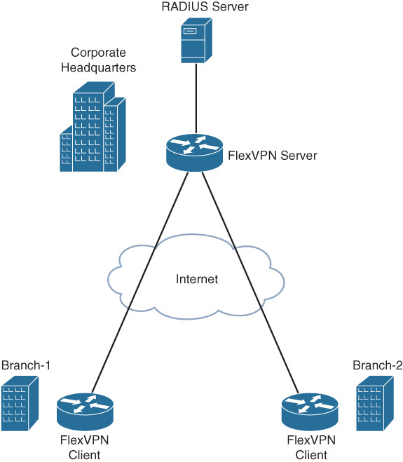
This scenario illustrates the scalable management of per-peer pre-shared keys using a RADIUS server. Figure 12-1 illustrates the topology with two branch offices connecting to the headquarters in a FlexVPN spoke-hub topology, using pre-shared key authentication.
The following example illustrates the configuration and verification of the FlexVPN AAA-based pre-shared key authentication on the branch and the hub routers. To demonstrate the configuration of symmetric as well as asymmetric pre-shared keys on the RADIUS server, the branch-1 router is configured to use symmetric pre-shared keys, and the branch-2 router is configured to use asymmetric pre-shared keys. The branch routers use a local IKEv2 keyring because only the pre-shared keys for the hub router are required. The hub router uses AAA-based pre-shared keys because the hub needs to have pre-shared keys for all the branch routers.
Configuration on the Branch-1 Router
The branch-1 router is configured with a unique local IKEv2 identity and a local IKEv2 keyring with a symmetric pre-shared key for authentication with the hub router at headquarters.
crypto ikev2 keyring local_keyring
peer hub-router
address 172.16.1.2
pre-shared-key branch1-hub-key
crypto ikev2 profile default
match identity remote fqdn hq.example.com
identity local fqdn branch1.example.com
authentication local pre-share
authentication remote pre-share
keyring local local_keyring
Configuration on the Branch-2 Router
The branch-2 router is configured with a unique local IKEv2 identity and a local IKEv2 keyring with asymmetric pre-shared keys for authentication with the hub router at headquarters.
crypto ikev2 keyring local_keyring
peer hub-router
address 172.16.1.2
pre-shared-key local branch2-to-hub-key
pre-shared-key remote hub-to-branch2-key
crypto ikev2 profile default
match identity remote fqdn hq.example.com
identity local fqdn branch2.example.com
authentication local pre-share
authentication remote pre-share
keyring local local_keyring
Configuration on the Hub Router
The AAA authorization is configured to use the RADIUS server to retrieve the IKEv2 pre-shared keys.
aaa new-model
aaa group server radius radius_group1
server name radius_server1
aaa authorization network aaa_psk_list group radius_group1
radius server radius_server1
address ipv4 172.16.1.3 auth-port 1645 acct-port 1646
key radius_server1_key
The IKEv2 name mangler is configured to derive the AAA username from the hostname portion of the peer IKEv2 identity of type FQDN. When each branch router is configured with a unique local FQDN identity, the name mangler will yield a unique AAA username for the pre-shared key lookup on the RADIUS server.
crypto ikev2 name-mangler aaa_psk_name_mangler
fqdn hostname
The IKEv2 profile is configured to match all the branch routers, based on the domain portion (example.com) of the peer FQDN identity. The profile is configured to use an AAA-based keyring that would retrieve the pre-shared keys, using AAA authorization from the RADIUS server specified in the referenced AAA method list. The referenced IKEv2 name mangler will yield a unique AAA username for pre-shared key lookup on the RADIUS server that is derived from the username portion the peer FQDN identity.
crypto ikev2 profile default
match identity remote fqdn domain example.com
identity local fqdn hq.example.com
authentication local pre-share
authentication remote pre-share
keyring aaa aaa_psk_list name-mangler aaa_psk_name_mangler
Configuration on the RADIUS Server
The RADIUS server is configured with a profile for each branch router. Note that the following configuration illustrates the Cisco VSA attribute format. The exact configuration steps would vary with the RADIUS implementation.
RADIUS profile for username “branch1”:
vsa cisco generic 1 string "ipsec:tunnel-password=branch1-key"
RADIUS profile for username “branch2”:
vsa cisco generic 1 string "ipsec:ikev2-password-local=hub-to-branch2-key"
vsa cisco generic 1 string "ipsec:ikev2-password-remote=branch2-to-hub-key"
The following example illustrates the logs on the hub capturing the retrieval of the symmetric pre-shared key from the RADIUS server for the branch-1 router. The debug crypto ikev2, debug crypto ikev2 internal, and debug radius authentication are enabled. Due to the verbose nature, internal debugging should be enabled only under the guidance of Cisco TAC.
IKEv2-INTERNAL:Fetching shared secret from AAA
IKEv2-INTERNAL:Name-mangler 'aaa_psk_name_mangler' returning mangled-name
'branch1' for name-type 1, name-len 19, name_string branch1.example.com
IKEv2-INTERNAL:Using AAA method list aaa_psk_list for peer branch1
IKEv2:(SA ID = 1):[IKEv2 -> AAA] Password request sent
RADIUS(0000019D): Send Access-Reques t to 172.16.1.3:1645 id 1645/145, len 133
RADIUS: authenticator 15 BF 00 82 37 B0 1B 60 - C2 55 00 9F 17 23 A9 5B
RADIUS: User-Name [1] 9 "branch1"
RADIUS: User-Password [2] 18 *
RADIUS: Calling-Station-Id [31] 12 "172.16.1.1"
RADIUS: Vendor, Cisco [26] 62
RADIUS: Cisco AVpair [1] 56 "audit-session-id=L2L4AC1G102ZO2L4AC1G101Z
I1F401F4ZM195"
RADIUS: Service-Type [6] 6 Outbound [5]
RADIUS: NAS-IP-Address [4] 6 172.16.1.2
RADIUS(0000019D): Sending a IPv4 Radius Packet
RADIUS(0000019D): Started 5 sec timeout
RADIUS: Received from id 1645/145 172.16.1.3:1645, Access-Accept, len 61
RADIUS: authenticator E0 55 BA 88 22 3E FC E6 - AF DA 03 B3 22 8C 76 8E
RADIUS: Vendor, Cisco [26] 41
RADIUS: Cisco AVpair [1] 35 "ipsec:tunnel-password=branch1-key"
RADIUS(0000019D): Received from id 1645/145
IKEv2:(SA ID = 1):[AAA -> IKEv2] Received password response
IKEv2-INTERNAL:Received symmmetric password from radius server
IKEv2:[Crypto Engine -> IKEv2] IKEv2 authentication data generation PASSED
IKEv2:(SESSION ID = 405,SA ID = 1):Verification of peer's authenctication data
PASSED
The following example illustrates the logs on the hub capturing the retrieval of the asymmetric pre-shared keys from the RADIUS server for the branch-2 router. The debug crypto ikev2, debug crypto ikev2 internal, and debug radius authentication are enabled.
IKEv2-INTERNAL:Fetching shared secret from AAA
IKEv2-INTERNAL:Name-mangler 'aaa_psk_name_mangler' returning mangled-name
'branch2' for name-type 1, name-len 19, name_string branch2.example.com
IKEv2-INTERNAL:Using AAA method list aaa_psk_list for peer branch2
IKEv2:(SA ID = 2):[IKEv2 -> AAA] Password request sent
RADIUS(0000019F): Send Access-Request to 172.16.1.3:1645 id 1645/147, len 133
RADIUS: authenticator E9 CB 55 31 65 06 83 48 - 00 60 15 3E 87 93 3C A9
RADIUS: User-Name [1] 9 "branch2"
RADIUS: User-Password [2] 18 *
RADIUS: Calling-Station-Id [31] 12 "172.16.1.4"
RADIUS: Vendor, Cisco [26] 62
RADIUS: Cisco AVpair [1] 56 "audit-session-
id=L2L4AC1G102ZO2L4AC1G104ZI1F401F4ZM197"
RADIUS: Service-Type [6] 6 Outbound [5]
RADIUS: NAS-IP-Address [4] 6 172.16.1.2
RADIUS(0000019F): Sending a IPv4 Radius Packet
RADIUS(0000019F): Started 5 sec timeout
RADIUS: Received from id 1645/147 172.16.1.3:1645, Access-Accept, len 127
RADIUS: authenticator F3 20 73 8E A8 B9 9F B8 - F0 02 A4 CA 64 47 66 82
RADIUS: Vendor, Cisco [26] 53
RADIUS: Cisco AVpair [1] 47 "ipsec:ikev2-password-local=hub-to-
branch2-key"
RADIUS: Vendor, Cisco [26] 54
RADIUS: Cisco AVpair [1] 48 "ipsec:ikev2-password-remote=branch2-to-
hub-key"
IKEv2:(SA ID = 2):[AAA -> IKEv2] Received password response
IKEv2-INTERNAL:Received local password from radius server
IKEv2-INTERNAL:Received remote password from radius server
IKEv2:[Crypto Engine -> IKEv2] IKEv2 authentication data generation PASSED
IKEv2:(SESSION ID = 407,SA ID = 2):Verification of peer's authenctication data
PASSED
FlexVPN User and Group Authorization
This FlexVPN remote access scenario demonstrates the use of FlexVPN group and user authorization to enforce common and specific policy for FlexVPN clients using group and user authorization on the FlexVPN server. The scenario uses two branch routers with the FlexVPN client connected to the FlexVPN server at the headquarters as illustrated in Figure 12-1. Each of the FlexVPN clients is configured to use a unique local IKEv2 identity of type FQDN. The FlexVPN server uses group authorization to retrieve the common enterprise DNS server IP address to be pushed to all clients and user authorization to retrieve a unique IP address to be assigned to each client.
The following example illustrates the FlexVPN client configuration at the branch routers and the FlexVPN server configuration at the headquarters.
FlexVPN Client Configuration at Branch 1
The FlexVPN client is configured with a unique local IKEv2 identity.
crypto ikev2 profile default
match identity remote fqdn hq.example.com
identity local fqdn branch1.example.com
authentication local pre-share
authentication remote pre-share
keyring local local_keyring
crypto ikev2 client flexvpn flex_client_profile
peer 1 172.16.1.2
connect manual
client connect Tunnel0
interface Tunnel0
ip address negotiated
tunnel source Ethernet0/0
tunnel destination dynamic
tunnel protection ipsec profile default
FlexVPN Client Configuration at Branch 2
The FlexVPN client is configured with a unique local IKEv2 identity.
crypto ikev2 profile default
match identity remote fqdn hq.example.com
identity local fqdn branch2.example.com
authentication local pre-share
authentication remote pre-share
keyring local local_keyring
crypto ikev2 client flexvpn flex_client_profile
peer 1 172.16.1.2
connect manual
client connect Tunnel0
interface Tunnel0
ip address negotiated
tunnel source Ethernet0/0
tunnel destination dynamic
tunnel protection ipsec profile default
Configuration on the FlexVPN Server
The AAA authorization is configured to use the local AAA and the RADIUS server for FlexVPN group and user authorizations.
aaa new-model
aaa group server radius radius_group1
server name radius_server1
aaa authorization network user_author_list group radius_group1
aaa authorization network group_author_list local
radius server radius_server1
address ipv4 172.16.1.3 auth-port 1645 acct-port 1646
key radius_server1_key
The IKEv2 name manglers are configured to derive the AAA username for the user and group authorizations from the hostname and the domain portions of the peer IKEv2 identity of type FQDN.
crypto ikev2 name-mangler user_author_name_mangler
fqdn hostname
crypto ikev2 name-mangler group_author_name_mangler
fqdn domain
The IKEv2 authorization policy, which acts as local AAA database for FlexVPN authorizations, is used for group authorization and is configured with a name that matches the domain portion of the peer IKEv2 identity. The authorization policy defines the enterprise DNS server IP address that is pushed to FlexVPN clients at all branches.
crypto ikev2 authorization policy example.com
dns 192.168.10.10
The IKEv2 profile is configured to match all the branch routers based on the domain portion (example.com) of the peer FQDN identity. The profile is configured with group authorization using local AAA as specified in the referenced AAA method list, and using the domain portion of the peer IKE identity as AAA username as specified in the referenced name mangler. The profile is configured with user authorization, using the RADIUS server as specified in the referenced AAA method list and using the hostname portion of the peer IKE identity as the AAA username as specified in the referenced name mangler. The group authorization provides the common DNS server IP address for all branches, and the user authorization provides a unique IP address for the FlexVPN client at every branch.
crypto ikev2 profile default
match identity remote fqdn domain example.com
identity local fqdn hq.example.com
authentication local pre-share
authentication remote pre-share
keyring aaa aaa_psk_list name-mangler aaa_psk_name_mangler
aaa authorization group psk list group_author_list name-mangler group_author_
name_mangler
aaa authorization user psk list user_author_list name-mangler user_author_name_
mangler
virtual-template 1
Configuration on the RADIUS Server
The RADIUS server is configured with a profile for each FlexVPN client with the name matching the hostname portion of the client’s IKE identity for user authorization. Each of the profiles is configured with a unique IP address that is assigned by the FlexVPN server to that client.
RADIUS profile for username “branch1”:
framed address 10.0.0.1 255.255.255.0
RADIUS profile for username “branch2”:
framed address 10.0.0.2 255.255.255.0
The following example illustrates the logs on the FlexVPN server that capture the local group authorization and RADIUS-based user authorization. The debug crypto ikev2, debug crypto ikev2 internal, and debug radius authentication are enabled.
IKEv2:Using mlist group_author_list and username example.com for group author
request
IKEv2:(SA ID = 1):[IKEv2 -> AAA] Authorisation request sent
IKEv2-INTERNAL:IKEv2 local AAA author request for 'example.com'
IKEv2:(SA ID = 1):[AAA -> IKEv2] Received AAA authorisation response
IKEv2-INTERNAL:Received group author attributes:
ipv4-dns: 192.168.10.10, route-accept any tag:1 distance:1,
The following logs capture RADIUS-based user authorization.
IKEv2:Using mlist user_author_list and username branch1 for user author request
IKEv2:(SA ID = 1):[IKEv2 -> AAA] Authorisation request sent
RADIUS(0000001D): Send Access-Request to 172.16.1.3:1645 id 1645/10, len 131
RADIUS: authenticator 76 2E F4 8B 41 A0 49 05 - E4 29 56 6A D3 6D 23 97
RADIUS: User-Name [1] 9 "branch1"
RADIUS: User-Password [2] 18 *
RADIUS: Calling-Station-Id [31] 12 "172.16.1.1"
RADIUS: Vendor, Cisco [26] 60
RADIUS: Cisco AVpair [1] 54 "audit-session-
id=L2L4AC1G102ZO2L4AC1G101ZI1F401F4ZO6"
RADIUS: Service-Type [6] 6 Outbound [5]
RADIUS: NAS-IP-Address [4] 6 172.16.1.2
RADIUS(0000001D): Sending a IPv4 Radius Packet
RADIUS(0000001D): Started 5 sec timeout
RADIUS: Received from id 1645/10 172.16.1.3:1645, Access-Accept, len 73
RADIUS: authenticator D5 CE AC 26 AA 67 89 A6 - 35 BC 09 FC 08 6B E9 F6
RADIUS: Framed-IP-Address [8] 6 10.0.0.1
RADIUS: Framed-IP-Netmask [9] 6 255.255.255.0
IKEv2:(SA ID = 1):[AAA -> IKEv2] Received AAA authorisation response
IKEv2-INTERNAL:Received user author attributes:
ipv4-addr: 10.0.0.1, ipv4-netmask: 255.255.255.0,
The following logs capture FlexVPN server pushing the common DNS server and a unique IP address to the client.
IKEv2:(SESSION ID = 6,SA ID = 1):Config-type: Config-reply
IKEv2:(SESSION ID = 6,SA ID = 1):Attrib type: ipv4-addr, length: 4, data: 10.0.0.1
IKEv2:(SESSION ID = 6,SA ID = 1):Attrib type: ipv4-netmask, length: 4, data:
255.255.255.0
IKEv2:(SESSION ID = 6,SA ID = 1):Attrib type: ipv4-dns, length: 4, data:
192.168.10.10
The show crypto ikev2 sa detailed command on FlexVPN client-1 displays the DNS server and assigned IP address pushed by the FlexVPN server.
FlexClient#show crypto ikev2 sa detailed
IPv4 Crypto IKEv2 SA
Tunnel-id Local Remote fvrf/ivrf Status
1 172.16.1.1/500 172.16.1.2/500 none/none READY
Encr: AES-CBC, keysize: 256, PRF: SHA512, Hash: SHA512, DH Grp:5, Auth sign:
PSK, Auth verify: PSK
Life/Active Time: 86400/29 sec
CE id: 1004, Session-id: 4
Status Description: Negotiation done
Local spi: 7BFDBB152E002029 Remote spi: E8700C8FDC94AA9A
Local id: branch1.example.com
Remote id: hq.example.com
Pushed IP address: 10.0.0.1
DNS Primary: 192.168.10.10
Logs Specific to FlexVPN Client-2
The following logs capture local group authorization.
IKEv2:Using mlist group_author_list and username example.com for group author
request
IKEv2:(SA ID = 2):[IKEv2 -> AAA] Authorisation request sent
IKEv2-INTERNAL:IKEv2 local AAA author request for 'example.com'
IKEv2:(SA ID = 2):[AAA -> IKEv2] Received AAA authorisation response
IKEv2-INTERNAL:Received group author attributes:
ipv4-dns: 192.168.10.10, route-accept any tag:1 distance:1,
The following logs capture RADIUS-based user authorization.
IKEv2:Using mlist user_author_list and username branch2 for user author request
IKEv2:(SA ID = 2):[IKEv2 -> AAA] Authorization request sent
RADIUS(00000021): Send Access-Request to 172.16.1.3:1645 id 1645/12, len 131
RADIUS: authenticator CB BD 72 FD 0E 06 B4 DA - 29 4F 1D 59 56 52 25 0E
RADIUS: User-Name [1] 9 "branch2"
RADIUS: User-Password [2] 18 *
RADIUS: Calling-Station-Id [31] 12 "172.16.1.4"
RADIUS: Vendor, Cisco [26] 60
RADIUS: Cisco AVpair [1] 54 "audit-session-
id=L2L4AC1G102ZO2L4AC1G104ZI1F401F4ZO7"
RADIUS: Service-Type [6] 6 Outbound [5]
RADIUS: NAS-IP-Address [4] 6 172.16.1.2
RADIUS(00000021): Sending a IPv4 Radius Packet
RADIUS(00000021): Started 5 sec timeout
RADIUS: Received from id 1645/12 172.16.1.3:1645, Access-Accept, len 139
RADIUS: authenticator 8D 16 2E 75 1C E8 9D 67 - CA E1 F1 E4 33 47 79 71
RADIUS: Framed-IP-Address [8] 6 10.0.0.2
RADIUS: Framed-IP-Netmask [9] 6 255.255.255.0
RADIUS(00000021): Received from id 1645/12
IKEv2:(SA ID = 2):[AAA -> IKEv2] Received AAA authorization response
IKEv2-INTERNAL:Received user author attributes:
ipv4-addr: 10.0.0.2, ipv4-netmask: 255.255.255.0,
The following logs capture FlexVPN server pushing the common DNS server and a unique IP address to the client.
IKEv2:(SESSION ID = 7,SA ID = 2):Config-type: Config-reply
IKEv2:(SESSION ID = 7,SA ID = 2):Attrib type: ipv4-addr, length: 4, data: 10.0.0.2
IKEv2:(SESSION ID = 7,SA ID = 2):Attrib type: ipv4-netmask, length: 4, data:
255.255.255.0
IKEv2:(SESSION ID = 7,SA ID = 2):Attrib type: ipv4-dns, length: 4, data:
192.168.10.10
The show crypto ikev2 sa detailed command on FlexVPN client-2 displays the DNS server and assigned IP address pushed by the FlexVPN server.
FlexClient2#show crypto ikev2 sa detailed
IPv4 Crypto IKEv2 SA
Tunnel-id Local Remote fvrf/ivrf Status
1 172.16.1.4/500 172.16.1.2/500 none/none READY
Encr: AES-CBC, keysize: 256, PRF: SHA512, Hash: SHA512, DH Grp:5, Auth sign:
PSK, Auth verify: PSK
Life/Active Time: 86400/7 sec
CE id: 1003, Session-id: 3
Status Description: Negotiation done
Local spi: 93E45A454B87A9D5 Remote spi: 841BBA759B822DBF
Local id: branch2.example.com
Remote id: hq.example.com
Pushed IP address: 10.0.0.2
DNS Primary: 192.168.10.10
FlexVPN Routing, Dual Stack, and Tunnel Mode Auto
This scenario demonstrates FlexVPN routing, dual stack, and tunnel mode auto using FlexVPN spoke-hub topology to connect branch sites to the headquarters. Figure 12-2 illustrates the topology where the branch sites connect to the HQ over IPv4 and IPv6 transport.
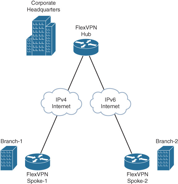
To demonstrate FlexVPN dual stack, all the sites have IPv4 and IPv6 LAN subnets, and branch-1 is connected to the headquarters over IPv4 transport and branch-2 over IPv6 transport.
To demonstrate tunnel mode auto, the hub site uses a single virtual-template interface with an IKEv2 profile configured with tunnel mode auto to clone virtual-access interfaces for spoke1 and spoke2 that are connected over IPv4 and IPv6 transport.
The FlexVPN routing is accomplished by specifying the local IPv4 and IPv6 LAN subnets as part of the user or group authorization policy, which can be either local or on the RADIUS server. These subnets are pushed to the peer using IKEv2 configuration exchange. The IKEv2 authorization policy configurations at the spokes and the hub demonstrate the different ways of specifying the local subnets to be pushed to the peer.
The following example illustrates the FlexVPN spoke configuration at the branch routers and the FlexVPN hub configuration at the headquarters.
FlexVPN Spoke Configuration at Branch-1
The AAA authorization method list for group authorization is configured to use local AAA.
aaa new-model
aaa authorization network group_author_list local
The name mangler is configured to return the domain portion of the peer FQDN identity.
crypto ikev2 name-mangler group_author_name_mangler
fqdn domain
Under the IKEv2 authorization policy, the route set interface command pushes the IPv4 and IPv6 addresses configured on the specified interface, or the virtual-access interface associated with the client VPN session if the interface is not specified, to the peer using IKEv2 configuration exchange. The peer programmatically adds static routes to these subnets pointing to the VPN tunnel interface.
crypto ikev2 authorization policy example.com
route set interface Ethernet1/0
route set interface
The IKEv2 profile is configured for local group authorization and the IKEv2 authorization policy acts as the local AAA database.
crypto ikev2 profile default
match identity remote fqdn hq.example.com
identity local fqdn branch1.example.com
authentication local pre-share key cisco
authentication remote pre-share key cisco
aaa authorization group psk list group_author_list name-mangler group_author_
name_mangler
The FlexVPN dual stack functionality is accomplished using GRE encapsulation on the tunnel interface and enabling both IPv4 and IPv6 on the tunnel interface. The tunnel mode command specifies the tunnel encapsulation mode as well as the transport type (IPv4 or IPv6). The default tunnel encapsulation mode is GRE-over-IPv4 (tunnel mode gre ip) and hence is not displayed in the running configuration. The tunnel source and destination use IPv4 addresses matching the transport type specified in tunnel mode command.
interface Tunnel0
ip address 10.0.0.1 255.255.255.0
ipv6 address FEC0::10:1/120
tunnel source Ethernet0/0
tunnel destination 172.16.1.2
tunnel protection ipsec profile default
The WAN interface is IPv4 and connects to FlexVPN hub at the headquarters.
interface Ethernet0/0
description IPv4 WAN interface
ip address 172.16.1.1 255.255.255.0
The LAN interface has IPv4 and IPv6 addresses to simulate the IPv4 and IPv6 LAN subnets.
interface Ethernet1/0
description LAN interface
ip address 192.168.0.1 255.255.255.0
ipv6 address FEC0::1:1/120
FlexVPN Spoke Configuration at Branch-2
The AAA authorization method list for group authorization is configured to use local AAA.
aaa new-model
aaa authorization network group_author_list local
The name mangler is configured to return the domain portion of the peer FQDN identity.
crypto ikev2 name-mangler group_author_name_mangler
fqdn domain
Under the IKEv2 authorization policy, along with the route set interface command that pushes the IPv4 and IPv6 addresses configured on the virtual-access interface associated with the client VPN session, the route set remote ipv4|ipv6 command specifies the IPv4 and IPv6 subnets that are pushed to the peer using IKEv2 configuration exchange and the peer programmatically adds static routes to these subnets pointing to the VPN tunnel interface.
crypto ikev2 authorization policy example.com
route set interface
route set remote ipv4 192.168.1.0 255.255.255.0
route set remote ipv6 FEC0::2:1/120
The IKEv2 profile is configured for local group authorization, and the IKEv2 authorization policy acts as the local AAA database.
crypto ikev2 profile default
match identity remote fqdn hq.example.com
identity local fqdn branch2.example.com
authentication local pre-share key cisco
authentication remote pre-share key cisco
aaa authorization group psk list group_author_list name-mangler group_author_
name_mangler
The FlexVPN dual stack functionality is accomplished using GRE encapsulation on the tunnel interface and enabling both IPv4 and IPv6 on the tunnel interface. The tunnel mode gre ipv6 command specifies the tunnel encapsulation mode as GRE as well as the transport as IPv6. The tunnel source and destination use IPv6 addresses matching the transport type specified in tunnel mode command.
interface Tunnel0
ip address 10.0.0.2 255.255.255.0
ipv6 address FEC0::10:2/120
tunnel source Ethernet0/0
tunnel mode gre ipv6
tunnel destination 2001::1:2
tunnel protection ipsec profile default
The WAN interface is IPv6 and connects to FlexVPN hub at the headquarters.
interface Ethernet0/0
description IPv6 WAN interface
no ip address
ipv6 address 2001::1:1/120
The LAN interface has IPv4 and IPv6 addresses to simulate the IPv4 and IPv6 LAN subnets.
interface Ethernet1/0
description LAN interface
ip address 192.168.1.1 255.255.255.0
ipv6 address FEC0::2:1/120
FlexVPN Hub Configuration at the HQ
The AAA authorization method list for group authorization is configured to use local AAA.
aaa new-model
aaa authorization network group_author_list local
The name mangler is configured to return the domain portion of the peer FQDN identity.
crypto ikev2 name-mangler group_author_name_mangler
fqdn domain
Under the IKEv2 authorization policy, along with the route set interface command that pushes the IPv4 and IPv6 addresses configured on the virtual-access interface associated with the client VPN session, the route set access-list [ipv6] command references the access lists, specifying the IPv4 and IPv6 subnets that are pushed to the peer by using the IKEv2 configuration exchange. The peer programmatically adds static routes to these subnets pointing to the VPN tunnel interface.
crypto ikev2 authorization policy example.com
route set interface
route set access-list v4-subnets
route set access-list ipv6 v6-subnets
ip access-list standard v4-subnets
permit 192.168.2.0 0.0.0.255
ipv6 access-list v6-subnets
permit ipv6 FEC0::3:0/120 any
The IKEv2 profile is configured for local group authorization, and the IKEv2 authorization policy acts as the local AAA database. The virtual-template 1 mode auto command specifies the virtual-template used to clone the virtual-access interfaces for the spoke sessions and also enables the auto detection of tunnel encapsulation mode and the transport type from the incoming session. Accordingly, it sets the tunnel mode command on the cloned virtual-access interface, overriding the setting derived from the virtual-template.
crypto ikev2 profile default
match identity remote fqdn domain example.com
identity local fqdn hq.example.com
authentication local pre-share key cisco
authentication remote pre-share key cisco
aaa authorization group psk list group_author_list name-mangler group_author_
name_mangler
virtual-template 1 mode auto
The FlexVPN dual stack functionality is accomplished by enabling both IPv4 and IPv6 on the virtual-template interface using ip unnumbered and ipv6 unnumbered commands. Because tunnel mode auto is enabled in the IKEv2 profile, the tunnel mode command on the cloned virtual-access interface is derived from the incoming session. The GRE encapsulation proposed by the spokes would enable carrying both IPv4 and IPv6 traffic over the VPN tunnel.
interface Loopback1
ip address 10.0.0.3 255.255.255.0
ipv6 address FEC0::10:3/120
interface Virtual-Template1 type tunnel
ip unnumbered Loopback1
ipv6 unnumbered Loopback1
tunnel protection ipsec profile default
The WAN interface is enabled for both IPv4 and IPv6 and connects to the FlexVPN spokes at the branches.
interface Ethernet0/0
description IPv4 and IPv6 WAN interface
ip address 172.16.1.2 255.255.255.0
ipv6 address 2001::1:2/120
The LAN interface has IPv4 and IPv6 addresses to simulate the IPv4 and IPv6 LAN subnets.
interface Ethernet1/0
description LAN interface
ip address 192.168.2.1 255.255.255.0
ipv6 address FEC0::3:1/120
Verification on FlexVPN Spoke at Branch-1
Before the FlexVPN session is established, there are no static routes through the VPN tunnel interface
FlexSpoke1#show crypto session
FlexSpoke1#show ip route static
FlexSpoke1#
The FlexVPN session between the FlexVPN spoke1 and the hub uses GRE encapsulation over IPv4 transport.
FlexSpoke1#show crypto session
Crypto session current status
Interface: Tunnel0
Profile: default
Session status: UP-ACTIVE
Peer: 172.16.1.2 port 500
Session ID: 1
IKEv2 SA: local 172.16.1.1/500 remote 172.16.1.2/500 Active
IPSEC FLOW: permit 47 host 172.16.1.1 host 172.16.1.2
Active SAs: 2, origin: crypto-map
The show crypto ikev2 sa detailed command output displays the IPv4 and IPv6 subnets received from the FlexVPN hub, using IKEv2 configuration exchange. The FlexVPN spoke programmatically adds static routes through the VPN tunnel interface to the subnets received from the hub.
FlexSpoke1#show crypto ikev2 sa detailed
IPv4 Crypto IKEv2 SA
Tunnel-id Local Remote fvrf/ivrf Status
1 172.16.1.1/500 172.16.1.2/500 none/none READY
Remote subnets:
10.0.0.3 255.255.255.255
192.168.2.0 255.255.255.0
IPv6 Remote subnets:
FEC0::10:3/128
FEC0::3:0/120
FlexSpoke1#show ip route static
10.0.0.0/8 is variably subnetted, 3 subnets, 2 masks
S 10.0.0.3/32 is directly connected, Tunnel0
S 192.168.2.0/24 is directly connected, Tunnel0
FlexSpoke1#show ipv6 route static
S FEC0::3:0/120 [1/0], tag 1
via Tunnel0, directly connected
S FEC0::10:3/128 [1/0], tag 1
via Tunnel0, directly connected
The FlexVPN GRE/IPv4 tunnel carries both IPv4 and IPv6 traffic to the FlexVPN hub LAN subnets learned through FlexVPN routing.
FlexSpoke1#clear crypto sa counters
FlexSpoke1#show crypto session detail | begin IPSEC
IPSEC FLOW: permit 47 host 172.16.1.1 host 172.16.1.2
Active SAs: 2, origin: crypto-map
Inbound: #pkts dec'ed 0 drop 0 life (KB/Sec) 4248161/2860
Outbound: #pkts enc'ed 0 drop 0 life (KB/Sec) 4248160/2860
FlexSpoke1#ping ipv6 FEC0::3:1
Type escape sequence to abort.
Sending 5, 100-byte ICMP Echos to FEC0::3:1, timeout is 2 seconds:
!!!!!
Success rate is 100 percent (5/5), round-trip min/avg/max = 1/1/1 ms
FlexSpoke1#show crypto session detail | begin IPSEC
IPSEC FLOW: permit 47 host 172.16.1.1 host 172.16.1.2
Active SAs: 2, origin: crypto-map
Inbound: #pkts dec'ed 5 drop 0 life (KB/Sec) 4248160/2841
Outbound: #pkts enc'ed 5 drop 0 life (KB/Sec) 4248159/2841
FlexSpoke1#ping 192.168.2.1
Type escape sequence to abort.
Sending 5, 100-byte ICMP Echos to 192.168.2.1, timeout is 2 seconds:
!!!!!
Success rate is 100 percent (5/5), round-trip min/avg/max = 1/1/1 ms
FlexSpoke1#show crypto session detail | begin IPSEC
IPSEC FLOW: permit 47 host 172.16.1.1 host 172.16.1.2
Active SAs: 2, origin: crypto-map
Inbound: #pkts dec'ed 10 drop 0 life (KB/Sec) 4248158/2805
Outbound: #pkts enc'ed 10 drop 0 life (KB/Sec) 4248158/2805
Verification on FlexVPN Spoke at Branch-2
Before the FlexVPN session is established, there are no static routes through the VPN tunnel interface
FlexSpoke2#show crypto session
FlexSpoke2#show ip route static
FlexSpoke2#
The FlexVPN session between the FlexVPN spoke2 and the hub uses GRE encapsulation over IPv6 transport.
FlexSpoke2#show crypto session
Crypto session current status
Interface: Tunnel0
Profile: default
Session status: UP-ACTIVE
Peer: 2001::1:2 port 500
Session ID: 1
IKEv2 SA: local 2001::1:1/500
remote 2001::1:2/500 Active
IPSEC FLOW: permit 47 host 2001::1:1 host 2001::1:2
Active SAs: 2, origin: crypto-map
The show crypto ikev2 sa detailed command output displays the IPv4 and IPv6 subnets received from the FlexVPN hub, using IKEv2 configuration exchange. The FlexVPN spoke programmatically adds static routes through the VPN tunnel interface to the subnets received from the hub.
FlexSpoke2#show crypto ikev2 sa detailed
IPv6 Crypto IKEv2 SA
Tunnel-id fvrf/ivrf Status
1 none/none READY
Local 2001::1:1/500
Remote 2001::1:2/500
Remote subnets:
10.0.0.3 255.255.255.255
192.168.2.0 255.255.255.0
IPv6 Remote subnets:
FEC0::10:3/128
FEC0::3:0/120
FlexSpoke2#show ip route static
10.0.0.0/8 is variably subnetted, 3 subnets, 2 masks
S 10.0.0.3/32 is directly connected, Tunnel0
S 192.168.2.0/24 is directly connected, Tunnel0
FlexSpoke2#show ipv6 route static
S FEC0::3:0/120 [1/0], tag 1
via Tunnel0, directly connected
S FEC0::10:3/128 [1/0], tag 1
via Tunnel0, directly connected
The FlexVPN GRE/IPv6 tunnel carries both IPv4 and IPv6 traffic to the FlexVPN hub LAN subnets learned through FlexVPN routing.
FlexSpoke2#clear crypto sa counters
FlexSpoke2#show crypto session detail | begin IPSEC
IPSEC FLOW: permit 47 host 2001::1:1 host 2001::1:2
Active SAs: 2, origin: crypto-map
Inbound: #pkts dec'ed 0 drop 0 life (KB/Sec) 4346787/3407
Outbound: #pkts enc'ed 0 drop 0 life (KB/Sec) 4346787/3407
FlexSpoke2#ping ipv6 FEC0::3:1
Type escape sequence to abort.
Sending 5, 100-byte ICMP Echos to FEC0::3:1, timeout is 2 seconds:
!!!!!
Success rate is 100 percent (5/5), round-trip min/avg/max = 1/1/1 ms
FlexSpoke2#show crypto session detail | begin IPSEC
IPSEC FLOW: permit 47 host 2001::1:1 host 2001::1:2
Active SAs: 2, origin: crypto-map
Inbound: #pkts dec'ed 5 drop 0 life (KB/Sec) 4346787/3387
Outbound: #pkts enc'ed 5 drop 0 life (KB/Sec) 4346786/3387
FlexSpoke2#ping 192.168.2.1
Type escape sequence to abort.
Sending 5, 100-byte ICMP Echos to 192.168.2.1, timeout is 2 seconds:
!!!!!
Success rate is 100 percent (5/5), round-trip min/avg/max = 1/1/1 ms
FlexSpoke2#show crypto session detail | begin IPSEC
IPSEC FLOW: permit 47 host 2001::1:1 host 2001::1:2
Active SAs: 2, origin: crypto-map
Inbound: #pkts dec'ed 10 drop 0 life (KB/Sec) 4346785/3361
Outbound: #pkts enc'ed 10 drop 0 life (KB/Sec) 4346785/3361
Verification on the FlexVPN Hub at HQ
The FlexVPN hub clones the virtual-access interface for FlexVPN spoke-1 and spoke-2 from the same virtual-template but automatically detects the encapsulation mode and transport IP type from the incoming session and sets the tunnel mode accordingly.
FlexVPN session and the virtual-access interface for FlexVPN spoke-1 that uses GRE/IPv4.
FlexHub#show crypto session
Crypto session current status
Interface: Virtual-Access2
Profile: default
Session status: UP-ACTIVE
Peer: 172.16.1.1 port 500
Session ID: 5
IKEv2 SA: local 172.16.1.2/500 remote 172.16.1.1/500 Active
IPSEC FLOW: permit 47 host 172.16.1.2 host 172.16.1.1
Active SAs: 2, origin: crypto-map
FlexHub#show derived-config interface virtual-access 2
Derived configuration : 220 bytes
interface Virtual-Access2
ip unnumbered Loopback1
ipv6 unnumbered Loopback1
tunnel source 172.16.1.2
tunnel destination 172.16.1.1
tunnel protection ipsec profile default
no tunnel protection ipsec initiate
end
FlexHub#show interfaces virtual-access 2 | include protocol/transport
Tunnel protocol/transport GRE/IP
The FlexVPN session and the virtual-access interface for FlexVPN spoke 2 that uses GRE/IPv6.
FlexHub#show crypto session
Crypto session current status
Interface: Virtual-Access1
Profile: default
Session status: UP-ACTIVE
Peer: 2001::1:1 port 500
Session ID: 6
IKEv2 SA: local 2001::1:2/500
remote 2001::1:1/500 Active
IPSEC FLOW: permit 47 host 2001::1:2 host 2001::1:1
Active SAs: 2, origin: crypto-map
FlexHub#show derived-config interface virtual-access 1
Derived configuration : 240 bytes
interface Virtual-Access1
ip unnumbered Loopback1
ipv6 unnumbered Loopback1
tunnel source 2001::1:2
tunnel mode gre ipv6
tunnel destination 2001::1:1
tunnel protection ipsec profile default
no tunnel protection ipsec initiate
end
FlexHub#show interfaces virtual-access 1 | include protocol/transport
Tunnel protocol/transport GRE/IPv6
The FlexVPN hub learns the IPv4 and IPv6 LAN subnets from FlexVPN spokes 1 and 2 and adds static routes to those subnets through the corresponding virtual-access interface.
FlexHub#show crypto ikev2 sa detailed
IPv4 Crypto IKEv2 SA
Tunnel-id Local Remote fvrf/ivrf Status
1 172.16.1.2/500 172.16.1.1/500 none/none READY
Remote subnets:
10.0.0.1 255.255.255.255
192.168.0.0 255.255.255.0
IPv6 Remote subnets:
FEC0::10:1/128
FEC0::1:0/120
IPv6 Crypto IKEv2 SA
Tunnel-id fvrf/ivrf Status
2 none/none READY
Local 2001::1:2/500
Remote 2001::1:1/500
Remote subnets:
10.0.0.2 255.255.255.255
192.168.1.0 255.255.255.0
IPv6 Remote subnets:
FEC0::10:2/128
FEC0::2:1/120
FlexHub#show ip route static
10.0.0.0/8 is variably subnetted, 4 subnets, 2 masks
S 10.0.0.1/32 is directly connected, Virtual-Access2
S 10.0.0.2/32 is directly connected, Virtual-Access1
S 192.168.0.0/24 is directly connected, Virtual-Access2
S 192.168.1.0/24 is directly connected, Virtual-Access1
FlexHub#show ipv6 route static
S FEC0::1:0/120 [1/0], tag 1
via Virtual-Access2, directly connected
S FEC0::2:0/120 [1/0], tag 1
via Virtual-Access1, directly connected
S FEC0::10:1/128 [1/0], tag 1
via Virtual-Access2, directly connected
S FEC0::10:2/128 [1/0], tag 1
via Virtual-Access1, directly connected
The FlexVPN hub can send and receive both IPv4 and IPv6 traffic to the FlexVPN spokes over the GRE/IPv4 and GRE/IPv6 tunnels.
Traffic to FlexVPN spoke 1:
FlexHub#ping 192.168.0.1
Type escape sequence to abort.
Sending 5, 100-byte ICMP Echos to 192.168.0.1, timeout is 2 seconds:
!!!!!
Success rate is 100 percent (5/5), round-trip min/avg/max = 1/1/1 ms
FlexHub#ping ipv6 FEC0::1:1
Type escape sequence to abort.
Sending 5, 100-byte ICMP Echos to FEC0::1:1, timeout is 2 seconds:
!!!!!
Success rate is 100 percent (5/5), round-trip min/avg/max = 1/1/1 ms
FlexHub#show crypto session interface virtual-access 2 detail | begin IPSEC
IPSEC FLOW: permit 47 host 172.16.1.2 host 172.16.1.1
Active SAs: 2, origin: crypto-map
Inbound: #pkts dec'ed 10 drop 0 life (KB/Sec) 4200943/2000
Outbound: #pkts enc'ed 10 drop 0 life (KB/Sec) 4200944/2000
Traffic to FlexVPN spoke 2:
FlexHub#ping 192.168.1.1
Type escape sequence to abort.
Sending 5, 100-byte ICMP Echos to 192.168.1.1, timeout is 2 seconds:
!!!!!
Success rate is 100 percent (5/5), round-trip min/avg/max = 1/1/1 ms
FlexHub#ping ipv6 FEC0::2:1
Type escape sequence to abort.
Sending 5, 100-byte ICMP Echos to FEC0::2:1, timeout is 2 seconds:
!!!!!
Success rate is 100 percent (5/5), round-trip min/avg/max = 1/1/1 ms
FlexHub#show crypto session interface virtual-access 1 detail | begin IPSEC
IPSEC FLOW: permit 47 host 2001::1:2 host 2001::1:1
Active SAs: 2, origin: crypto-map
Inbound: #pkts dec'ed 10 drop 0 life (KB/Sec) 4339994/2178
Outbound: #pkts enc'ed 10 drop 0 life (KB/Sec) 4339996/2178
FlexVPN Client NAT to the Server-Assigned IP Address
This scenario demonstrates the FlexVPN client applying NAT source address translation to the LAN traffic that is sent through the FlexVPN tunnel. The source address of the LAN packets is translated to the address assigned by the FlexVPN server. This scenario is equivalent of the EzVPN client mode. The following example illustrates the NAT configuration on the FlexVPN client.
Configuration on the FlexVPN Client
The AAA authorization is configured to use local AAA for FlexVPN group authorization.
aaa new-model
aaa authorization network group_author_list local
crypto ikev2 name-mangler group_author_name_mangler
fqdn domain
The IKEv2 authorization policy, which is used for local group authorization in this example, is configured to accept the routes pushed by the peer and to push the VPN tunnel IP address to the peer.
crypto ikev2 authorization policy default
route set interface
crypto ikev2 profile default
match identity remote fqdn hq.example.com
identity local fqdn branch1.example.com
authentication local pre-share key cisco
authentication remote pre-share key cisco
aaa authorization group psk list group_author_list default
crypto ikev2 client flexvpn flex_client_profile
peer 1 172.16.1.2
connect manual
client connect Tunnel0
The loopback interface configured with ip nat inside simulates the LAN subnet for which NAT translation is applied. In production networks, the interface will be a routable physical interface.
interface Loopback0
description simulates LAN subnet
ip address 192.168.0.1 255.255.255.0
ip nat inside
ip virtual-reassembly in
The ip nat outside, combined with the NAT rule defined in the following example, applies network access translation to all the LAN traffic forwarded to tunnel interface. Note that the translation is done before encryption. The source address of all the packets is translated to the IP address of the tunnel interface which is obtained from the FlexVPN server through IKEv2 configuration exchange due to the ip address negotiated command.
interface Tunnel0
ip address negotiated
ip nat outside
ip virtual-reassembly in
tunnel source Ethernet0/0
tunnel destination dynamic
tunnel protection ipsec profile default
interface Ethernet0/0
description WAN interface
ip address 172.16.1.1 255.255.255.0
Define the NAT rule to apply source address translation to traffic forwarded to the tunnel interface. The source address of all the packets is translated to the IP address of the tunnel interface.
ip nat inside source route-map flex-route-map interface Tunnel0 overload
route-map flex-route-map permit 1
match interface Tunnel0
Verification on the FlexVPN Client
The following commands display the IP address assigned by the FlexVPN server and the remote LAN subnets pushed by the server. The client adds routes to the remote subnets.
FlexClient#show crypto ikev2 sa detail
IPv4 Crypto IKEv2 SA
Tunnel-id Local Remote fvrf/ivrf Status
1 172.16.1.1/500 172.16.1.2/500 none/none READY
Pushed IP address: 10.0.0.1
DNS Primary: 192.168.10.10
Remote subnets:
10.0.0.10 255.255.255.255
192.168.1.0 255.255.255.0
FlexClient#show ip route static
4.0.0.0/24 is subnetted, 1 subnets
S 4.4.4.0 is directly connected, Tunnel0
10.0.0.0/8 is variably subnetted, 3 subnets, 2 masks
S 10.0.0.10/32 is directly connected, Tunnel0
S 192.168.1.0/24 is directly connected, Tunnel0
The following debug ip packet logs capture the traffic from the local to the remote LAN that is forwarded to the tunnel interface where the packet source address is translated to the server-assigned IP address by NAT and then the packet is encrypted and sent out.
FlexClient#ping 192.168.1.1 source 192.168.0.1 repeat 1
Type escape sequence to abort.
Sending 1, 100-byte ICMP Echos to 192.168.1.1, timeout is 2 seconds:
Packet sent with a source address of 192.168.0.1
!!!!!
Success rate is 100 percent (5/5), round-trip min/avg/max = 1/1/1 ms
FlexClient#
IP: s=192.168.0.1 (local), d=192.168.1.1, len 100, local feature, NAT(2), rtype 0,
forus FALSE, sendself FALSE, mtu 0, fwdchk FALSE
IP: s=192.168.0.1 (local), d=192.168.1.1 (Tunnel0), len 100, sending
NAT translation is applied.
IP: s=10.0.0.1 (local), d=192.168.1.1 (Tunnel0), len 100, output feature, Post-
routing NAT Outside(26), rtype 1, forus FALSE, sendself FALSE, mtu 0, fwdchk FALSE
Packet undergoes GRE encapsulation and encryption.
IP: s=10.0.0.1 (local), d=192.168.1.1 (Tunnel0), len 100, post-encap feature,
IPSEC Post-encap output classification(16), rtype 1, forus FALSE, sendself FALSE,
mtu 0, fwdchk FALSE
IP: s=10.0.0.1 (local), d=192.168.1.1 (Tunnel0), len 100, sending full packet
IP: s=172.16.1.1 (local), d=172.16.1.2 (Ethernet0/0), g=172.16.1.2, len 168,
forward
IP: s=172.16.1.1 (local), d=172.16.1.2 (Ethernet0/0), len 168, sending full packet
The show ip nat translations and show ip nat statistics command outputs display the NAT translation entries.
FlexClient#show ip nat translations
Pro Inside global Inside local Outside local Outside global
icmp 10.0.0.1:15 192.168.0.1:15 192.168.1.1:15 192.168.1.1:15
FlexClient#show ip nat statistics
Total active translations: 1 (0 static, 1 dynamic; 1 extended)
Peak translations: 4, occurred 01:13:02 ago
Outside interfaces:
Tunnel0
Inside interfaces:
Loopback0
Hits: 65 Misses: 0
CEF Translated packets: 30, CEF Punted packets: 0
Expired translations: 13
Dynamic mappings:
-- Inside Source
[Id: 1] route-map flex-route-map interface Tunnel0 refcount 1
FlexVPN WAN Resiliency, Using Dynamic Tunnel Source
This scenario demonstrates FlexVPN WAN resiliency using the FlexVPN client dynamic tunnel source feature. The example uses a branch site connected to the headquarters over MPLS and the Internet as primary and secondary WAN links as illustrated in Figure 12-3.
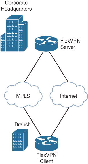
The dual-homed branch router is configured as the FlexVPN client and the dual-homed edge router at the head end site is configured as a FlexVPN server. The FlexVPN client would connect to the FlexVPN server over MPLS as long as it is available, fall back to the Internet when the MPLS link goes down, and revert back to MPLS when it comes back up. The transport networks don’t strictly have to be MPLS or Internet, but they could be 3G, 4G, satellite, or any bearer that runs IP. This feature is especially useful with expensive, usage-based backup links such as 3G, 4G, or satellite where the backup link is used only during the time the primary link is unavailable.
The following example illustrates the FlexVPN WAN resiliency configuration and verification on the FlexVPN client.
FlexVPN Client Configuration on the Dual-Homed Branch Router
The Serial 0/0 and Serial 1/0 interfaces in this example simulate MPLS and Internet WAN links. The track objects track the line protocol status of the two serial interfaces.
track 1 interface Serial0/0 line-protocol
track 2 interface Serial1/0 line-protocol
The FlexVPN client profile is configured to track the line protocol status of the Serial 0/0 and Serial 1/0 interfaces and use them as the preferred and backup tunnel source interface. The peer address is the address of the loopback interface on the FlexVPN server that is reachable through both Serial 0/0 and Serial 1/0 interfaces. This example is intended to be very simple in nature. The ability to track objects allows for very powerful configurations to be used. Rather than simply monitoring the line protocol, a track could be created to monitor for the presence of a prefix in the routing table, or an SLA which can check connectivity to a next-hop IP address.
The profile is configured with the default connect auto mode to be able to initiate the FlexVPN connection without any user intervention when there is a need to switch between the preferred and backup tunnel source interfaces, based on their availability.
crypto ikev2 client flexvpn flex-client
peer 1 172.16.3.1
source 1 Serial0/0 track 1
source 2 Serial1/0 track 2
client connect Tunnel0
The tunnel interface is associated with the FlexVPN client profile, using the client connect Tunnel0 command in the client profile. With the tunnel source dynamic command, the tunnel source is dynamically set by the client profile, based on the availability of the source interfaces specified in the profile.
interface Tunnel0
ip address 10.0.0.1 255.255.255.0
ipv6 address FEC0::10:1/120
tunnel source dynamic
tunnel destination dynamic
tunnel protection ipsec profile default
The Serial 0/0 and Serial 1/0 interfaces in this example simulate MPLS and Internet WAN links.
interface Serial0/0
description MPLS
ip address 172.16.1.1 255.255.255.0
keepalive 2
serial restart-delay 0
interface Serial1/0
description Internet
ip address 172.16.2.1 255.255.255.0
keepalive 2
serial restart-delay 0
The FlexVPN server loopback address is configured to be reachable through both Serial 0/0 and Serial 1/0 interfaces.
ip route 172.16.3.1 255.255.255.255 Serial0/0
ip route 172.16.3.1 255.255.255.255 Serial1/0
Verification on the FlexVPN Client
FlexVPN client is initially connected to the FlexVPN server with Serial 0/0 as tunnel source interface.
FlexClient#show crypto ikev2 client flexvpn
Profile : flex-client
Current state:ACTIVE
Peer : 172.16.3.1
Source : Serial0/0
ivrf : IP DEFAULT
fvrf : IP DEFAULT
Backup group: Default
Tunnel interface : Tunnel0
When the Serial 0/0 interface goes down, the associated track object and the FlexVPN connection go down as captured in the following syslogs.
%TRACK-6-STATE: 1 interface Se0/0 line-protocol Up -> Down
* %FLEXVPN-6-FLEXVPN_CONNECTION_DOWN: FlexVPN(flex-client) Client_public_addr =
172.16.1.1 Server_public_addr = 172.16.3.1
%LINEPROTO-5-UPDOWN: Line protocol on Interface Tunnel0, changed state to down
%CRYPTO-6-ISAKMP_ON_OFF: ISAKMP is OFF
%CRYPTO-6-ISAKMP_ON_OFF: ISAKMP is ON
%LINEPROTO-5-UPDOWN: Line protocol on Interface Serial0/0, changed state to down
The FlexVPN profile uses the next configured and available interface (Serial 1/0) as tunnel source and re-establishes the FlexVPN connection.
%LINEPROTO-5-UPDOWN: Line protocol on Interface Tunnel0, changed state to up
%FLEXVPN-6-FLEXVPN_CONNECTION_UP: FlexVPN(flex-client) Client_public_addr =
172.16.2.1 Server_public_addr = 172.16.3.1
FlexClient#show crypto ikev2 client flexvpn
Profile : flex-client
Current state:ACTIVE
Peer : 172.16.3.1
Source : Serial1/0
ivrf : IP DEFAULT
fvrf : IP DEFAULT
Backup group: Default
Tunnel interface : Tunnel0
When the Serial 0/0 interface comes back up, the FlexVPN connection switches back to Serial 0/0 as the tunnel source interface.
TRACK-6-STATE: 1 interface Se0/0 line-protocol Down -> Up
%FLEXVPN-6-FLEXVPN_CONNECTION_DOWN: FlexVPN(flex-client) Client_public_addr =
172.16.2.1 Server_public_addr = 172.16.3.1
%LINEPROTO-5-UPDOWN: Line protocol on Interface Tunnel0, changed state to down
%CRYPTO-6-ISAKMP_ON_OFF: ISAKMP is OFF
%CRYPTO-6-ISAKMP_ON_OFF: ISAKMP is ON
%LINEPROTO-5-UPDOWN: Line protocol on Interface Serial0/0, changed state to up
%LINEPROTO-5-UPDOWN: Line protocol on Interface Tunnel0, changed state to up
%FLEXVPN-6-FLEXVPN_CONNECTION_UP: FlexVPN(flex-client) Client_public_addr =
172.16.1.1 Server_public_addr = 172.16.3.1
FlexClient#show crypto ikev2 client flexvpn
Profile : flex-client
Current state:ACTIVE
Peer : 172.16.3.1
Source : Serial0/0
ivrf : IP DEFAULT
fvrf : IP DEFAULT
Backup group: Default
Tunnel interface : Tunnel0
FlexVPN Hub Resiliency, Using Backup Peers
This scenario demonstrates FlexVPN hub resiliency, using the FlexVPN client backup peers feature. The example uses a branch site connected to the headquarters that has dual WAN edge routers for redundancy as illustrated in Figure 12-4.
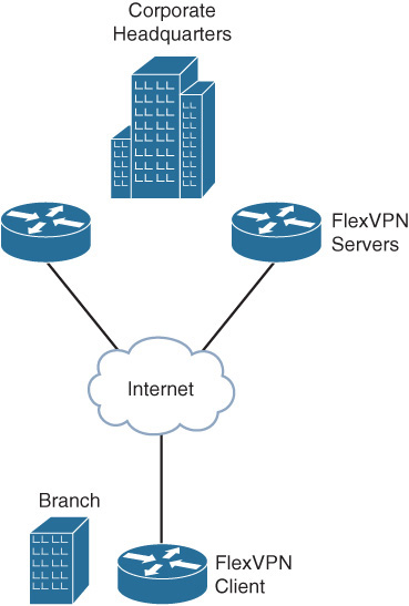
The branch router is configured as FlexVPN client, and each of the edge routers at the headquarters is configured as a FlexVPN hub. The FlexVPN client is configured with primary and secondary hubs as peers. The client would connect to the primary hub, based on a track object that tracks its reachability and would fall back to the backup FlexVPN hub only when the preferred hub is not available, reverting back to the primary once it is available. The following example illustrates the configuration on the FlexVPN client for FlexVPN hub resiliency, using backup peers.
FlexVPN Client Configuration on the Branch Router
A track object is configured to track the reachability of the primary hub.
track 1 ip sla 1 reachability
ip sla 1
icmp-echo 172.16.2.1
frequency 5
ip sla schedule 1 start-time now
The FlexVPN client profile is configured with primary and secondary peers. The client would connect to the primary peer when the associated track object that tracks its reachability is up and would fall back to secondary only when the primary is not reachable. The peer reactivate command ensures that the connection reverts to the primary when it is available again. The profile is configured with the default connect auto mode to be able to initiate the FlexVPN connection without any user intervention when there is a need to switch between the primary and secondary peers based on the availability of the primary.
crypto ikev2 client flexvpn flex-client
peer 1 172.16.2.1 track 1
peer 2 172.16.3.1
peer reactivate
client connect Tunnel0
The tunnel interface is associated with the FlexVPN client profile, using the client connect Tunnel0 in the client profile. With the tunnel destination dynamic command, the tunnel destination is dynamically set by the client profile, based on the availability of the primary and secondary peers.
interface Tunnel0
ip address 10.0.0.1 255.255.255.0
tunnel source Ethernet0/0
tunnel destination dynamic
tunnel protection ipsec profile default
The Ethernet 0/0 connects to the Internet that provides connectivity to the primary and secondary peers.
interface Ethernet0/0
description Internet
ip address 172.16.1.1 255.255.255.0
Verification on the FlexVPN Client
The FlexVPN client is initially connected to the primary peer.
FlexClient#show crypto ikev2 client flexvpn
Profile : flex-client
Current state:ACTIVE
Peer : 172.16.2.1
Source : Ethernet0/0
ivrf : IP DEFAULT
fvrf : IP DEFAULT
Backup group: Default
Tunnel interface : Tunnel0
When the primary peer becomes unreachable, the associated track object and the FlexVPN connection go down as captured in the following syslogs.
%TRACK-6-STATE: 1 ip sla 1 reachability Up -> Down
%FLEXVPN-6-FLEXVPN_CONNECTION_DOWN: FlexVPN(flex-client) Client_public_addr =
172.16.1.1 Server_public_addr = 172.16.2.1
%LINEPROTO-5-UPDOWN: Line protocol on Interface Tunnel0, changed state to down
The client establishes the connection to the secondary peer.
%LINEPROTO-5-UPDOWN: Line protocol on Interface Tunnel0, changed state to up
%FLEXVPN-6-FLEXVPN_CONNECTION_UP: FlexVPN(flex-client) Client_public_addr =
172.16.1.1 Server_public_addr = 172.16.3.1
FlexClient#show crypto ikev2 client flexvpn
Profile : flex-client
Current state:ACTIVE
Peer : 172.16.3.1
Source : Ethernet0/0
ivrf : IP DEFAULT
fvrf : IP DEFAULT
Backup group: Default
Tunnel interface : Tunnel0
When the primary peer comes back up, the FlexVPN connection switches back to the primary.
%TRACK-6-STATE: 1 ip sla 1 reachability Down -> Up
%FLEXVPN-6-FLEXVPN_CONNECTION_DOWN: FlexVPN(flex-client) Client_public_addr =
172.16.1.1 Server_public_addr = 172.16.3.1
%LINEPROTO-5-UPDOWN: Line protocol on Interface Tunnel0, changed state to down
%LINEPROTO-5-UPDOWN: Line protocol on Interface Tunnel0, changed state to up
%FLEXVPN-6-FLEXVPN_CONNECTION_UP: FlexVPN(flex-client) Client_public_addr =
172.16.1.1 Server_public_addr = 172.16.2.1
FlexClient#show crypto ikev2 client flexvpn
Profile : flex-client
Current state:ACTIVE
Peer : 172.16.2.1
Source : Ethernet0/0
ivrf : IP DEFAULT
fvrf : IP DEFAULT
Backup group: Default
Tunnel interface : Tunnel0
FlexVPN Backup Tunnel, Using Track-Based Tunnel Activation
This scenario demonstrates FlexVPN tunnel as a backup WAN connection, using the FlexVPN client track-based tunnel activation feature. The example uses a branch site connected to the headquarters over MPLS and Internet with MPLS as the primary WAN link and the FlexVPN tunnel over the Internet as the secondary WAN link. The FlexVPN client is configured to track the MPLS link, and when it goes down, the FlexVPN tunnel over the Internet would be activated to act as a backup WAN link. The FlexVPN tunnel is terminated once the MPLS link is available again. The following example illustrates the configuration of the FlexVPN backup tunnel, using track-based tunnel activation.
The Serial 1/0 interface in this example simulates the MPLS WAN link. The track object tracks the line protocol status of the Serial 1/0 interface.
track 1 interface Serial1/0 line-protocol
The FlexVPN client profile is configured to initiate the FlexVPN tunnel when the track object 1 goes down. As the track object 1 monitors the availability of the MPLS link, the FlexVPN tunnel is triggered only when the MPLS interface is down.
crypto ikev2 client flexvpn flex-client
peer 1 172.16.1.2
connect track 1 down
client connect Tunnel0
interface Tunnel0
ip address 10.0.0.1 255.255.255.0
tunnel source Ethernet0/0
tunnel destination dynamic
tunnel protection ipsec profile default
The Ethernet 0/0 and Serial 1/0 interfaces in this example simulate Internet and MPLS WAN links.
interface Ethernet0/0
description Internet
ip address 172.16.1.1 255.255.255.0
interface Serial1/0
description MPLS
ip address 172.16.2.1 255.255.255.0
keepalive 2
serial restart-delay 0
Verification on the FlexVPN Client
The FlexVPN tunnel is initially inactive as the MPLS link is available.
FlexClient#show interfaces Serial 1/0 | include line protocol
Serial1/0 is up, line protocol is up
FlexClient#show crypto ikev2 client flexvpn
Profile : flex-client
Current state:CONNECT_REQUIRED
Backup group: Default
Tunnel interface : Tunnel0
When the MPLS link (Serial 1/0 interface) goes down, the associated track object goes down, and the FlexVPN tunnel over the Internet is initiated as captured in the following syslog messages.
%TRACK-6-STATE: 1 interface Se1/0 line-protocol Up -> Down
%LINEPROTO-5-UPDOWN: Line protocol on Interface Tunnel0, changed state to up
%FLEXVPN-6-FLEXVPN_CONNECTION_UP: FlexVPN(flex-client) Client_public_addr =
172.16.1.1 Server_public_addr = 172.16.1.2
FlexClient#show crypto ikev2 client flexvpn
Profile : flex-client
Current state:ACTIVE
Peer : 172.16.1.2
Source : Ethernet0/0
ivrf : IP DEFAULT
fvrf : IP DEFAULT
Backup group: Default
Tunnel interface : Tunnel0
When the MPLS link (Serial 1/0 interface) comes back up, the FlexVPN tunnel is terminated.
%TRACK-6-STATE: 1 interface Se1/0 line-protocol Down -> Up
%FLEXVPN-6-FLEXVPN_CONNECTION_DOWN:FlexVPN(flex-client) Client_public_addr =
172.16.1.1 Server_public_addr = 172.16.1.2
FlexClient#show crypto ikev2 client flexvpn
Profile : flex-client
Current state:CONNECT_REQUIRED
Backup group: Default
Tunnel interface : Tunnel0
Summary
This chapter illustrated some of the FlexVPN deployment scenarios with sample configuration and verification steps. The scenario on AAA-based pre-shared keys illustrated how the RADIUS server can be leveraged for scalable management of pre-shared keys, especially at the headend that needs to deal with large number of peers.
The scenario with FlexVPN authorization illustrated how the user and group authorization can be combined together to enforce specific and common authorization policy across the sites. The scenario on dual stack and tunnel mode auto illustrated how these features simplify the deployments while accomplishing the required functionality of IPv4 and IPv6 overlay over IPv4 or IPv6 transport. The scenario also demonstrated how FlexVPN routing simplifies overlay routing.
The chapter concluded with FlexVPN NAT and the various FlexVPN resiliency scenarios.