While IPSec is a versatile and functional protocol for securing IP, it is not a complete solution for all deployments, and there are still other issues that may need to be addressed. Many protocols desire to use IPSec to satisfy their security concerns and these have different problems that IPSec addresses incompletely. Indeed, while IPSec is a solution to a large problem, it is a problem to other protocols—for instance, network address translation (NAT).
Compression algorithms work by detecting patterns in data and eliminating duplicates. Encryption renders plaintext into seemingly random ciphertext. The better the encryption algorithm, the more random the ciphertext will appear. Regardless of the algorithm, the effective randomness of the cipher text means that it cannot be compressed. Compressing encrypted data can even result in expansion!
As more people start using encryption at the network layer, they will soon realize that their link-layer compression (e.g., in PPP) is not only failing, but is actually a detriment to their bandwidth because it will most likely increase the amount of data being sent over PPP. Turning off link-layer compression will help make things better, in the sense that the encrypted data will not be expanded by the compression algorithm, but the user will still notice that his effective bandwidth is not what it was before he decided to encrypt his data.
When security becomes enough of a nuisance that its benefits are weighed against the benefits of not having security, some people will opt for no security, the path of least resistance. And that is A Bad Thing. Ideally, one should not have to notice security.
The IP Payload Compression Protocol (PCP) was designed to address this problem. PCP is a stateless protocol that provides network layer compression. The idea is to compress, then encrypt. That way, the benefits of both compression and encryption can be realized.
Histories are used by compression algorithms to keep track of past patterns—by learning from the past history of the data, they are not condemned to repeat it, and in fact they eliminate it. But, PCP cannot take advantage of a compression algorithm's history because it must be stateless. This is because there is no guarantee that IP packets will even be delivered, much less delivered in order, and it is therefore impossible to maintain a proper compression history. The overhead of trying to maintain a history, and having to repeatedly flush it and start over when a packet is dropped or received out of order, is not worth the effort. Therefore, when a compression algorithm that utilizes histories is employed by PCP, it must flush its history buffer after each compression and decompression.
PCP, like AH and ESP, is an IP protocol. It has been assigned the number 108. An IP packet whose protocol field is 108, or an IPSec header whose next header field is 108, indicates that following is a PCP header and compressed data. Figure 12.1 shows an PCP header.
The next header field should be obvious at this point. It indicates what type of data was compressed. The PCP header contains a field much like the SPI field of an IPSec header—a compression parameters index (CPI). This field, along with the destination address of the outer IP header, identifies a compression security association.
It was decided to make the CPI two bytes (instead of four like an SPI) for two reasons: alignment and a desire to keep the header as small as possible to not override the savings obtained by compressing. By making a two-byte CPI, the compressed data will begin on a 32-bit aligned boundary (keeping with IPSec) and the header is only 4 bytes long. This leaves a single byte, which is not used, and is therefore marked in the standard fashion as reserved.
The PCP security association is very minimal. Since there is really no state to retain (no key, no antireplay protection, and no history for instance), all that is needed is an algorithm identifier. In that way, a single entity can support multiple compressed sessions with various peers with different algorithms, if desired.
Like AH and ESP, PCP can be negotiated by IKE. The IPSec DOI contains a DOI-specific protocol value (which differs from its IP protocol) for PCP and also algorithm identifiers for the two-compression algorithms defined for use with PCP: LZS and Deflate. In theory, IKE could negotiate PCP in the absence of any accompanying IPSec protocol, but what's the point? The whole reason PCP was defined was to enable compression when encrypting at the IP layer or below. If encryption is not being negotiated there is no point in having IKE go through its two phases and public key operations, only to negotiate compression parameters. Also, since the performance of PCP is lessened because of its stateless requirement, if someone wanted to compress and not encrypt, they could realize much better results by compressing at a higher layer where a history can be utilized—for instance, the session layer.
Processing of PCP differs from the IPSec protocols because compression is not always successful. Sometimes a PCP header will not be added to outbound packets and therefore a PCP header cannot be expected in each inbound packet, unlike IPSec processing where the header is always added and always expected.
In output processing, PCP is always done prior to either AH or ESP. If the compression algorithm defined in the PCP SA utilizes a compression history, that history must be flushed before the algorithm is used to compress data for PCP. The protected payload—either an upper-layer protocol in the case of transport mode, or an entire IP datagram in the case of tunnel mode—is then compressed by the algorithm defined in the PCP SA. If compression was successful, a PCP header is prepended to the compressed data and the resulting package is passed to IPSec for further processing and encapsulation. If compression is not successful, if the data did not actually get smaller, then the original uncompressed data is passed to IPSec processing without a PCP header. An outbound packet will only have a PCP header if the data was successfully compressed, which makes sense. This makes input processing a bit easier.
In input processing, the IPSec- and (possibly) PCP-protected packet is going to be sent to IPSec input processing because the protocol field of the IP header will be either AH or ESP. As the packet is decapsulated and the various IPSec headers are peeled off, the next header field of the IPSec headers must be checked. When that field indicates that a PCP header follows, we know that following that header will be compressed data. If the algorithm in the PCP SA—identified by the CPI in the header, the protocol (PCP), and the destination address in the outer IP header—utilizes a compression history, that history must be flushed prior to decompression. If the data cannot be successfully decompressed, the packet must be dropped, because it would be impossible to reconstruct the original data. If successful, the decompressed packet will be either an IP datagram—if PCP was performed in tunnel mode—or upper-layer protocol data—if PCP was performed in transport mode. In the latter case, a new IP datagram must be constructed. The next header field in the PCP header becomes the protocol in the new IP datagram, the payload length is adjusted, and a new checksum is computed.
Since a PCP header will not always exist in an inbound packet, the lack of one must not be construed as an error condition in the way it is when an expected IPSec header is missing. If IKE negotiates ESP and PCP together, the packet may or may not have a PCP header, but it must always have an ESP header. Similarly, if IKE negotiates AH and ESP and PCP all together, the packet must always have an AH header and an ESP header but, depending on the data, may or may not contain a PCP header.
Taking the time and processing power to compress data only not to use the result can be a severe drag on performance. This can negate any benefit that compression would have. Some heuristics can be employed in PCP processing to maximize compression and minimize the number of times that compression is unsuccessful. Depending on the algorithm a lower-bound of data length can be fixed. Data less than, say 128 bytes, should not even be attempted to be compressed. The data is so small anyway, and any compression benefit would probably not be worth the effort; we'd be adding four bytes for the PCP header anyway. Also, by noting that successive packets will most likely not compress if the packet before did not, a good heuristic to employ is not to attempt compression on the next n packets upon unsuccessful compression of a packet. (Depending on the algorithm and the traffic, n can be 5 or 10 or maybe more.) A good example of this is when the traffic being protected is Web traffic. Any GIF image in a Web page would not compress because it's already compressed, but the text in the page would compress quite successfully. The packets that comprise the GIF will be successive, and when the first fails compression, the rest will too. By not attempting compression on the next n packets, this segment can be skipped over and processing power saved by not wasting time attempting to compress packets that will most likely not compress.
Just as there are different layers in the OSI networking model where encryption is possible, compression can be implemented at various layers as well. Compressing at a layer higher than IP will have the benefit of the resulting traffic being represented by fewer packets instead of the same number of smaller packets. Routing fewer packets is preferable to routing smaller packets. Also, when compression is done at a protocol layer higher than the network layer, a history may be utilized. Compression works much better with histories, so data will usually compress better at the session layer for example than at the network layer.
In spite of its drawbacks, PCP has been implemented by a number of vendors. It's not clear whether they all support PCP by itself or only in conjunction with an IPSec protocol, but PCP does exist and it is being used.
IPSec is a point-to-point protocol. One side encrypts, the other decrypts, and both sides share a key or keys. There is a single recipient and single sender for each IPSec packet. In multicast, there are many recipients of a single packet, and quite often, many senders to a particular (single) multicast address. This is a completely different paradigm for IPSec. Antireplay protection cannot work if there are many senders. Data source authentication cannot work if all people in a group share a key. In addition, IKE won't work because it is designed to establish a shared key between two parties, but in multicast there must be a shared group key (or perhaps a tree of shared keys) that each recipient must have. Obviously, applying IPSec to multicast is tricky.
An IPSec SA is identified by the triple of protocol, SPI, and destination address. This address can be a multicast address. The only issue there is allocation of the SPI. In regular IPSec, it is the destination that chooses the SPI. In multicast, there is no single “destination” for a given address. Instead, the SPI is allocated by a group controller who is also, most likely, responsible for key generation and access control (more on this later when we discuss multicast key management).
So by just flipping the responsibility for SPI generation we can use IPSec to secure multicast traffic, right? Not quite. Remember that IPSec provides not only confidentiality and data integrity, it also provides source authentication and antireplay services. The latter two will fail in a multicast environment where many entities share a key and can all send packets to the same address. If everyone shares a key, all you can say about the sender of a “secured” multicast packet is that it was sent by someone in the group, not necessarily by the claimed sender. Similarly, if many people are sending packets to the same multicast address with the same SPI, there is no way to synchronize the antireplay counters so that no single counter value is used more than once and that the window could properly advance.
Antireplay is something many users of multicast can live without, but source authentication of multicast traffic is not. It is critical for many multicast applications, and is a nontrivial problem that has yet to be adequately solved. Imagine a company that sells news or information. The company's reputation is based on the reliability of the information it sells. If it decided secure multicast was a way to save money and still deliver its information only to select recipients (which is similar to the motivation in setting up a VPN instead of paying for an expensive leased line), it would quickly lose its reputation and its customers, because any subscriber could forge “news” items or inject bogus information into the otherwise legitimate feed. Obviously, this problem has to be solved.
One way is to have each sender digitally sign each packet sent. This would provide nonreputable source authentication, but at a great cost. Current digital signature technologies (RSA, DSA) are too slow for bulk data protection. The bit rate of delivery would drop so drastically as to be largely unusable for most multicast applications. A speed-up can be realized by using a small exponent for an RSA key pair. This might be acceptable to certain applications for which forgery of the entire stream is a problem, but one or two packets is not. For others, though, this is still unacceptable.
Another technique described by Gennaro and Rohatgi in the proceedings of Crypto '97 uses a single public key (asymmetric) signature and a symmetrically-keyed hashing technique that takes advantage of the fact that the sender can know what the next packet it is going to send will be (Figure 12.2). This idea uses a strong digital signature on a keyed hash of the second packet appended to the first packet sent. The signed digest in the first packet is a keyed hash of the second packet and it can be checked when the second packet is received. Accompanying the second packet is a digest from a keyed hash of the third packet. If a keyed hash of the second packet (including the digest for the third packet) can validate the signature obtained in the first packet, the sender of the first packet can be unambiguously identified. Then, when the third packet is received, which carries a keyed hash digest of the fourth packet, it can be authenticated by computing a keyed hash digest and checking that against the value in the second packet, and so on.
Notice that each keyed hash is over the entire next packet, including the digest of the subsequent packet. This is to prevent someone from hijacking the stream in the middle and injecting bogus packets into the stream. Of course, the requirement this places on the sender is that the sender must know all of the input prior to sending the first packet. For many situations this is unacceptable, but for some, like the multicasting of movies or software distributions, it is entirely acceptable. The sender can generate the entire stream and sends out the first packet only after the entire data set has been processed.
The only requirement on the receiver is that he or she maintain a small buffer to hold the authenticating information for the next packet.
This is a very clever idea that is extended to multisender groups in the paper by using one-time signatures. Of course, this technique has problems if a packet is lost or received out of order since the chaining technique would collapse. Chung Kei Wong and Simon Lam in the paper “Digital Signatures for Flows and Multicasts,” extended this technique to adapt to unreliable communications.
Another technique for source authentication of multicast traffic (by G. Itkis, in a presentation made to the Crypto '96 conference) uses the authentication digest technique of AH, but extends it to use many digests. The idea is that for any particular sender of a group, there are n keys. Each member of the group, and therefore recipient of the traffic, is granted k of the n keys, where k < n (Figure 12.3). Each packet is sent with n digests representing a keyed hash with each of the n keys, and each recipient validates those digests that correspond to the keys he or she holds. If any of the digests for which he or she holds a key is incorrect, the packet is dropped. If they are all correct he or she must then assume the rest of the digests that were not checked are correct. Obviously, one member could forge packets to other members who shared the same keys, but given a suitably large n and a relatively small k the number of members that share the same set of keys will be small. It is possible to forge packets if a coalition of i members were to form, such that the union of all keys shared by all i members is equal to n. The probability of such a coalition forming is remote, though, because members do not have a way of learning who other members are (or of learning which members are unscrupulous enough to enter into such an illegitimate coalition) or what keys other members are holding. The drawback of this technique is the added computation on the sender of n keyed hashes and also the difficulty in determining the distribution of keys such that it will be difficult, if not impossible, for members of the group to form a forgery coalition.

This idea has been subsequently incorporated into a paper “Multicast Security: A Taxonomy of Secure Multicast Protocols and Efficient Authentication Schemes” by Canetti, Garay, Itkis, Micciancio, Naor, and Pinkas, which was presented at the INFOCOM '99 conference. This paper also includes several complexity measures between this scheme and a scheme using digital signatures.
Obviously, no single method of providing source authentication of multicast is acceptable for all, or even most, applications. Much work continues to be done in this field.
Key management is also a difficult problem in multicast security. As mentioned, IKE is designed to establish a shared key (or keys) between two peers. It does so by performing an authenticated Diffie-Hellman exchange. While it is possible to extend a Diffie-Hellman to more than two members, it becomes a computational nightmare. Also, the addition or deletion of a single member would require another n-way exchange (where n is the current number of members of the group) at great computational cost. Some new key management technique is necessary. Most multicast key management protocols use a centralized key distribution center, or centers, that provide the key to qualified entities.
Other issues affecting multicast key management are join latency—it should not take prohibitively long to obtain the key(s) and receive secured multicast traffic; rekeying—it should be easy to retire an old key and distribute a new one to all key members; and, forced member removal—if a member of the group must be removed, the group must be rekeyed in such a way such that this member is not able to obtain the new key.
There are quite a few multicast key-management protocols. Some are specific to a multicast routing protocol while others are protocol-independent. Some construct a key distribution tree, which is congruent to a multicast (data) delivery tree, while others require no such structures.
All of the most popular methods of multicast key management share a common method of using unicast technology for initial key acquisition. A new or candidate member of a secure group uses a unicast protocol to obtain the key from a key holder or key manager. Almost all differ in who that key holder or key manager is, and where in the network that entity resides, though. They also differ in how rekeying is done; many of the key-management proposals try to optimize the time it takes to forcibly remove a member from the group.
Three members of the United States National Security Agency, Debby Wallner, Eric Harder, and Ryan Agee, wrote an influential paper on multicast key management and submitted it to the IETF. This document describes a wide variety of applications and explores the various architectural requirements they place on a secure multicast solution.
While the analysis of the various scenarios is quite complete (and the reader is encouraged to obtain a copy of this work), it is the architecture analysis and, most important, the recommended architecture that makes this paper important. Four possible architectures are discussed, each of which performs basically the same function, albeit in slightly differing manners.
The first is the most obvious: manual key distribution. The group key is distributed to members in some out-of-band manner without any sort of on-line key exchange. It is possible to take advantage of this single step to distribute multiple keys, each with a limited lifetime. The drawback of this approach is that it scales poorly to large or dynamic groups. It is also inadequate if forced member removal is necessary.
The next technique described is where a shared secret is established between each group member and the key holder. This shared secret can be, for instance, the result of an authenticated Diffie-Hellman exchange. This secret can be used as a key encrypting key (KEK), which can be used to distribute the shared group key to individual members. Each member would retain the secret it shares with the key distributor, but the key distributor would have to retain the secrets of all the group members to whom it has distributed the key. This is attractive due to its simplicity and the ability to implement such a system in a straightforward way. The drawback is, again, scaling. As the number of members in the group rises, so does the work required by the key distributor. It must establish a shared secret with each party, and for large groups, the key distributor could easily be overwhelmed. At the least, the key acquisition latency would be too great. Another drawback is what happens when a single member is forcibly removed. The new key would have to be individually distributed to each remaining group member. Again, the latency to rekey would be too much for large groups.
The rekey latency can be addressed by adding a “complimentary variable” to the shared KEK scheme described above. In this technique, a set of these variables is sent to each member, along with the group key (all encrypted by the KEK, of course). Each member is assigned a complimentary variable but is given the complimentary variable of every other member of the group. So for a group of n members, there will be n complimentary variables and each member j receives all variables i where i = 1,2,..., n, but i ! = j. In other words, each member knows the complimentary variable of every other member but does not know her own. To forcibly remove a member from the secure group, say “member 20,” the group owner sends a message saying “remove member 20 and all members generate a new key using the existing key and the complimentary variable for member 20 (this can be done, for instance, by hashing the two together). Since member 20 did not have her own complimentary variable, she is unable to compute the new key and is, effectively, out of the group. The main drawback to this is that each time a member joins the group a new complimentary variable must be sent out to all established group members. Another drawback is that each member must store the complimentary variable of every other member of the group, and for large groups, this storage requirement can become unbearable.
In light of the deficiencies of these approaches, the technique recommended by the authors is that of a hierarchical tree. In this technique there is no one single key, there are many. The keys are maintained by the group owner by constructing and maintaining the hierarchical tree (Figure 12.4). Each node in the tree represents another key. At the root of the tree is the main group key. Each group member is a leaf of the tree and each member is given the set of keys from the root, through all intermediate nodes, to the leaf that represents itself.
To construct such a tree, the key server (who may or may not be the root of the tree) establishes a shared secret (a KEK) with each leaf node, each user. The root key and the key of the leaf's parent nodes are transmitted to it encrypted in its KEK. The tree nodes (all parts that are not leaves) are merely logical and do not represent any actual group entity. Addition of a new user entails only establishment of a KEK and then a single message containing all the keys of its parent nodes encrypted in that KEK.
Forced member removal is interesting. Imagine that the tree in Figure 12.4 should be rekeyed in such a manner that member N is unable to obtain the new key—that member N is forcibly removed from the group. To do this, all keys held by user N must be renewed and distributed to all the people that need them, in this case, those that hold keys F, B, or A.
The rekey is performed bottom up. Therefore, the first key to change is key F. Before that key can be used, it must be transmitted to all those that use it, in this case O and P (remember N is being removed). Therefore, the new key F is sent to leaf O in O's key and to leaf P in P's keys. Next, B is replaced by sending it encrypted in E, the new F, and G. A is then rekeyed by sending it to all members encrypted in the new C, D, and the new B.
Rekeying is much less labor-intensive and impacts a smaller amount of members than the previous techniques. For a group of n members, the group owner must do 2 * log n key encryptions to rekey the group. In addition, the storage requirements to implement this technique are not onerous. For a tree of depth d, each user must store d+1 keys while the group owner must keep all keys.
A multicast key distribution protocol specific to core-based trees (CBT) is described by Tony Ballardie in RFC1949. CBT is a multicast architecture that uses central routers, called cores, to build a multicast delivery tree.
RFC1949 ties multicast key distribution to the actual joining of the secure group. Access control is applied to the multicast join and the key is distributed along with a join acknowledgment. The utility of this approach is open to debate since there is no way to insure that only group members receive multicast traffic. It is generally placed on a shared medium, after all. Given that the data is encrypted, this is generally not viewed as a problem. On the other hand, by tying key acquisition to the group join, two birds are effectively being killed with a single stone.
In RFC1949, a group access package comprised of the group key, a key encrypting key (for rekeying the group key), and security association information, is distributed by authorized routers of the distribution tree to joining nodes. Each router that is part of the CBT tree will eventually become a group key distribution center (GKDC) and has the authority to distribute a group access package to a host wishing to join the secure group.
IPSec is assumed to protect the multicast data traffic using an SA created from the group access package.
When a node wishes to join a secure CBT tree, it sends an IGMP report to the group. In this report is a token, similar to the cookies that IKE uses, which is generated by, and is unique to, the host. This token is signed by the host wishing to join the group, and therefore to acquire the group key.
The local designated router (DR) authenticates the report by checking the signature on the token. If valid and the local designated router is already a GKDC, it can perform an access control check on the host and directly distribute a group access package if the host passes. If the DR is not a GKDC, and is therefore not part of the CBT, it must form a join request and target the tree's core. The join request contains the host's token, the DR's token, and is digitally signed by the DR. The entire message is sent to the core via the next-hop router on path back to the core.
The next-hop router must then authenticate the join request and, if successful, construct a new join request with the original host's token, its own token. This new join request is digitally signed by the next-hop router and sent toward the core. This is repeated until the core, or a DR that is already a GKDC, receives the join message.
When the core (or a GKDC on the CBT) receives the join, it must authenticate the host that started this whole chain of messaging. If the host passes the access control check, it constructs a join acknowledgment message and sends it back along the path that the original join took. Just as the join was reconstructed and resigned at each hop, so must the join acknowledgment be authenticated, decrypted, reconstructed, re-encrypted, signed, and forwarded on toward the host. At each hop, the group access package, including access control information, will be retained, since each router, now part of the tree, becomes a GKDC.
This group access package is actually the access control list for the group, plus two sets of group key, plus key encrypting key, plus SA parameters. One of the sets is encrypted in the public key of the host that is the ultimate destination of the join acknowledgment and the other is encrypted in the public key of the next-hop router. The final hop is at the host, who can decrypt the access control package (since it was encrypted by the core with his public key) and recover all information necessary to create an SA to receive the multicast data.
The hop-by-hop processing required by RFC1949 will impose considerable join latency on members. As the tree is built, the need for a join request to be sent all the way to the core is mitigated, but there will, most likely, still be cases where a single request for the key (and also for membership in the group) will require several hops, and therefore several public key operations. There is also an issue with this technique necessitating storage of the group key (and the key encrypting key) in all routers that comprise the CBT. The more people, or in this case routers, that know a key, the less likely that key will remain a secret. RFC1949 is a secure and scalable method of distributing group keys, but its costs are considerable.
A protocol called the multicast key management protocol (MKMP) has been proposed by Dan Harkins and Naganand Doraswamy (yes, the authors of this book) as a way to quickly distribute keys to members of a multicast group in a manner that can scale from small groups to large, and from dense groups to sparse. It is not bound to any key-management protocol or secure multicast framework. In this manner, it is appropriate for use in most any secure multicast deployment.
In MKMP there is a single entity, called the group key manager (or GKM) who is responsible for generating the keys used to protect the multicast data and also for generating all access control information. The GKM also decides whether to delegate key distribution authority to other entities, called group key distributors (GKDs). It is this delegation that allows MKMP to scale.
If the GKM elects not to delegate authority to distribute keys, it would resemble the second technique described by Wallner, et al, where each group member shares a secret with the key manager. In this case, the GKM must be prepared to satisfy all requests for the key. For a group that is anticipated to have not very many members, this isn't a problem. (Note that the GKM will know how large the group can become because he is constructing the access control information. He or she alone can determine who obtains the key.) For a large group, this may be a problem, because a protocol that provides mutual authentication, like MKMP, requires public key operations to do the authentication.
When key distribution delegation is desired, the GKM solicits key distributors by sending a special message to the multicast data group. This message contains the identities of the entities that the GKM desires to become key distributors, or GKDs, and is sent with the Router Alert (RFC 2113) option set (Figure 12.5). This identity can be an explicit IP address, a subnetwork, a distinguished name from a certificate, the distinguished name of an acceptable certification authority (CA), or any combination of the same. For instance, the GKM can solicit GKDs that reside in a particular subnet and have certificates that are signed by a particular CA.

Of course, initially, the multicast data distribution tree will be either nonexistent or quite small, and the solicitation message will not travel far and will most likely not be received by any of the targeted key distributors. As hosts join the group and obtain the key from the only available source—the GKM—the multicast tree will be constructed and the solicitation message will be able to be received by more designated key distributors.
By setting the Router Alert option on the solicitation message, all routers on the multicast distribution tree will inspect this packet. A non-MKMP-aware router will not know how to parse it and will merely forward the packet on, albeit on its slow switched path. An MKMP-aware router will be able to parse the packet and determine whether it is on the list of potential GKDs. If it is, and it desires to become a GKD, it can obtain the group key from the GKM using the MKMP's key distribution protocol. Along with the key, the GKD also obtains group access control information so it can know who is allowed to obtain the key and who is not allowed to obtain the key, and something called the group information tuple, or GIT. The GIT is a token that can be used to prove key distribution authority to host. The GIT contains the multicast data group address and the identity of the GKD, thus binding the router to the group. The GIT is signed by the GKM to prove that the router identified in the GIT as a GKD is authorized to distribute the key. Otherwise, why would a host believe a router that claims the authority to distribute keys for a specific multicast data group?
As the multicast data distribution tree is built, the solicitation messages will be received by more and more routers and therefore have a higher chance of reaching potential GKDs. For any given area, the first host that joins the group will have to obtain the key from the GKM because there will be no branch of the multicast data distribution tree for it to attach to and therefore no neighborhood GKD. This branch must be built using the underlying multicast routing protocol (PIM, CBT, etc.). But after that initial key acquisition from the GKM, the key solicitation messages will be received by routers on the multicast data distribution tree and any potential GKD in that area would receive the message and acquire the key, thereby becoming a full-fledged GKD. Subsequent requests to obtain the group key by candidate group members in that area can be made to the GKD.
Note that GKDs will therefore arise only in areas that already have multicast data group members. This is A Good Thing. There will be no unnecessary distribution of the key to entities that would not have an opportunity to distribute the key. The fewer places this group key resides, the higher the chance of it remaining secret.
A host that wishes to obtain the key must first decide from where to obtain it. From the GKM or from a neighborhood GKD? This determination is made by probing for a GKD in its immediate area. This probe takes the form of a message sent to a special multicast address, the ALL_MKMP_DEVICES group, in a flood-and-prune-style with administrative scoping to prevent it from being sent to too wide an area. This flood-and-prune method of probing will result in a temporal state being retained in routers that must flood this packet out of its other interfaces. For routers that run multicast routing protocols like PIM this won't be a problem, but for other protocols, like DVMPR, this could be a problem because the state will be retained for upward of two hours.
If a router receives a probe for a group for which it is a GKD, it must respond to the sending host with a probe response indicating that it is a duly authorized GKD for the particular multicast data group. This response must therefore contain the GIT that the GKD received from the GKM at the time it obtained the group key.
A host that receives a response to its probe can obtain the key from the router that responded, provided, of course, that the GIT is authentic and has been signed by the GKM. A host that receives no response to its probe must obtain the key from the GKM itself.
In this manner key distribution scales with the group for which the key is being distributed.
MKMP also defines a key distribution protocol[5] that allows for the key to be distributed in a mutually authenticated manner. It contains a liveness proof to prevent replay attacks against the key holder. It also distributes the key with a minimum of expensive public key operations. Key distribution takes place between a key acquirer and key holder (either the GKM or a GKD to which this responsibility has been delegated). The protocol uses public key cryptography to encrypt a random number of the key acquirer's choosing. This random number is encrypted in the public key of the key holder and transmitted to the key holder. The key holder can then decrypt the random number and generate another, seemingly random, number by taking the exclusive-or (XOR) of the secret key and the key acquirer's random number. This new number, the result of the XOR operation, is encrypted in the public key of the key acquirer and transmitted back. The key acquirer, upon receipt, can decrypt this number and take the XOR of it with his or her original random number and construct the secret key. Each side must also compute an authenticating hash that contains cookies (when the group key is requested both the GKM and GKDs generate a cookie, similar to an IKE cookie, unique to the requestor) and state from the exchange that binds the parties to the exchange and proves that they are active participants in the exchange.
MKMP assumes that IPSec will be used to secure the actual transmission of the multicast data. It therefore also provides a mechanism for the key holder to distribute security association information to the key requestor along with the key.
MKMP can scale, but its ability to scale depends on proper delegation of distribution authority. If the GKM makes a poor choice of routers to whom it solicits key distribution authority, it can end up servicing most, if not all, requests for the key. On the plus side, MKMP distributes the key with only two public key operations on each side. Contrast this with the technique of using an authenticated Diffie-Hellman exchange to establish the shared key between the member and key holder, which would require two exponentiations for the Diffie-Hellman and probably two public key operations for the authentication. On the downside, the flood-and-prune technique MKMP employs to probe for GKDs may be inappropriate for certain multicast data routing protocols.
There are quite a few protocols to distribute a group key, many more than are described here. Each has its benefits and costs that must be weighed when choosing a protocol to use. Because no one protocol is satisfactory, work continues on new protocols and also on improving existing protocols by lessening the impact of, or eliminating, their weaknesses. The descriptions of these protocols may change in the future.
Multicast security is being addressed in the IRTF (a sister of the IETF that does the Research prior to the Engineering, it's the Internet Research Task Force) because the issues with it are so large that it is necessary to do some research prior to beginning the engineering of a solution. The IRTF working group is called SMuG, for Secure Multicast Group. This group is chartered to deal with all aspects of multicast security and introduces techniques and protocols back into the Multicast Security (MSEC) Working Group of the IETF where solutions based on IRTF research are engineered to become standard protocols.
Encryption poses certain questions and concerns. By using encryption, a company can keep confidential information secret while utilizing a public network. It can be used in e-commerce situations—in fact, e-commerce must use encryption because otherwise credit card and personal information would be transmitted from customer to store insecurely. Encryption can also be used by unscrupulous individuals to hide their nefarious acts. For instance, a child pornographer could encrypt all evidence of his illegal activity or terrorists could use IPSec to securely plan and carry out acts of terrorism.
Because of the latter, many governments in the world severely restrict when, where, and by whom encryption can be used. This makes it easier to keep tabs on certain groups or individuals, but also prevents the Internet from being used to its full advantage.
In an attempt to balance the competing concerns of law enforcement, business, and individuals, a concept of key recovery has been proposed. The idea is that the key(s) used for encryption will be stored in a repository maintained by a bonded company that will only give up the keys when presented with a lawful warrant. It sounds nice in theory, but in practice has many problems that are not properly addressed. A thorough evaluation of key recovery was compiled by several noted cryptographers (Abelson, Anderson, Bellovin, Benaloh, Blaze, Diffie, Gilmore, Neumann, Rivest, Schiller, and Schneier) in the paper “The Risks of Key Recovery, Key Escrow, and Trusted Third-Party Encryption” and readers are encouraged to find a copy of this paper.
It should also be noted that, ignoring all the technological problems of implementing a key recovery infrastructure, there are also very serious civil liberty concerns. Few people have an implicit trust of their government and there is ample evidence of government agencies, from almost every country in the world, engaging in illegal collection of evidence and illegal spying. Making technological allowances for what is for all intents and purposes spying outrages many people. It may also be in violation of law in certain countries. The Fourth Amendment to the United States Constitution provides for search and seizure by lawfully authorized government agents, but nothing states that the targets of the search must make affirmative efforts to guarantee the success of the search. In fact, the Fifth Amendment states that a man cannot be forced to be a witness against himself, which is basically what forced key recovery is doing. This is an emotional issue that probably cannot be resolved. There are just too many strongly held beliefs on each side.
Cryptography is no longer a science reserved to governments or their militaries. The genie is out of the bottle, so to speak, when cryptographic tools are readily available at local computer stores or on the Internet. The notion of key recovery may be too late.
IKE uses an ephemeral Diffie-Hellman exchange to derive the shared secret used for IPSec key generation. Through the beauty of Diffie-Hellman, only the active participants in the exchange know the secret. Also, each flow (protected by a single SA or SA bundle) has unique session keys. There is no long-term secret (as in months or years) that could be stored with the key recovery center to enable key recovery of IPSec-protected sessions. The long-term keys IKE uses are for authentication only and there is no reason why these keys should be escrowed at a key recovery center. This makes key recovery in IPSec very problematic.
A proposal has been made on how to extend IKE to do key recovery. This proposal takes advantage of the fact that additional, optional payloads can be chained on to any IKE message. It also makes use of ISAKMP options for the commit bit flag and the authentication-only flag.
Remember, when the commit bit is used in an IKE quick mode exchange, the exchange is extended on a single message. This message is not very interesting and only consists of the authenticating hash and a message saying “I'm connected.” There is nothing particularly secret there, and passing that final message in the clear would not be a serious detriment to the security of the overall quick mode exchange.
The key recovery extension to IKE passes this last message in the clear by setting the authentication-only (i.e., no encryption) flag. (The message remains authenticated because the hash is included, but none of the payloads are encrypted.) It also adds a new payload, a key recovery payload, to the message. This payload contains the SA information, including the keys, and is encrypted in the public key of the key recovery center.
To “recover” the keys, the agents send a copy of the key recovery payload to the key recovery center (along with their warrant, of course!). The payload is decrypted by the center and the resulting information—SPI, algorithms, keys—is given back to the agents who use it to decrypt the targeted traffic.
Interestingly, an IKE implementation that implements this proposal could interoperate with another implementation that doesn't. Of course, this has problems because it works only if the responder is the party that wishes to do key recovery. If the initiator of the quick mode desires to do key recovery (for whatever reason) and the responder does not, the key recovery payload will not be sent. The initiator has no way of forcing the responder to send this information. Should the initiator terminate the session because the key was not leaked? That's not really clear.
This proposal to add key recovery capability to IKE was not introduced in the IETF, where all the other documents that define IKE and IPSec were, because the IETF has made a public statement against key recovery. RFC1984 (the number selection was probably intentional) is the statement of the Internet Architecture Board (IAB) and the Internet Engineering Steering Group (IESG) which formally declares the IETF's opposition to key recovery. Even without the formal statement represented by RFC1984 it is doubtful that the IPSec working group of the IETF would embrace this proposal. There are just too many technical, legal, and political issues that surround key recovery.
A protocol called the Layer 2 Tunneling Protocol (L2TP) has been defined by the PPP Extensions working group of the IETF as a way to, you guessed it, tunnel layer 2 data. Remember the OSI model of networking from Chapter 2. The link layer is layer 2, the layer at which data is sent directly from one entity to another over the physical connection (which is at layer 1).
The link layer can be either packet-switched or circuit-switched but regardless, the data being transferred is addressed from one physical entity to another. There is no concept of a route across the network at layer 2. One can say that layer 2 transmissions are point to point.
In fact, the main use of L2TP is to tunnel data that is already in the point-to-point protocol (PPP). Usually, when one uses a modem the data is sent from the local computer's modem to a remote modem encapsulated in PPP. The physical connection is the phone circuit and data is transferred directly from one physical endpoint to another. The information being sent across this point-to-point link is PPP-encapsulated data, usually IP datagrams. Upon receipt of PPP data, the PPP header is stripped off to reveal the IP data inside. This data is then routed normally as if it had been encapsulated in an Ethernet frame and taken off a directly connected network.
Quite often the modem that a local computer dials into is not on the network to which the PPP-encapsulated data is destined. For instance, a traveling businessman in a hotel room can dial a local Internet Service Provider (ISP) who will terminate his PPP packets and forward the resulting IP datagrams onto the Internet toward his ultimate destination. Using a local service provider would most likely be cheaper due to long distance phone charges or the maintenance of an 800 number by the businessman's company. The problem then is that the businessman's computer has an ISP-assigned address (which is foreign to the network that he is trying to reach) and will most likely fail any sort of access control or security check that the network will apply to his packets.
If the PPP data, which is layer 2 data, could be transmitted across the network and be terminated by a server on the network to which he is trying to reach, he could take advantage of all the services of his network (local IP address, resource sharing, security, and access control) and save on the cost by still placing a local call to a local ISP. This is where L2TP comes into play.
L2TP tunnels begin and terminate at the network layer. An L2TP Access Concentrator (LAC) is the client end of the connection while an L2TP Network Server (LNS) is the server side. The PPP packets are encapsulated in an L2TP header that are, themselves, encapsulated in IP. These IP packets can traverse the network just like ordinary IP datagrams. When such a packet is received, the LNS demultiplexes the session using information in the L2TP header. It can then decapsulate the PPP data in a session-specific manner and forward the internal IP datagrams onto the local network.
There are two types of L2TP configurations: compulsory, where the client connects to an ISP acting as a LAC which tunnels PPP packets to the LNS (Figure 12.6a); and voluntary, where the client acts as the LAC and brings up an L2TP tunnel directly with the LNS after first bringing up a connection to the ISP (Figure 12.6b). In the former, L2TP runs in the ISP-controlled LAC. In the latter, L2TP runs on the client itself.

When using L2TP, the businessman can obtain an IP address from the enterprise network he is trying to access. This will allow his local computer to appear as if it is on the enterprise network. The addressing could even be non-routable in the ISP's domain! From a logical point of view, it will be the same as his computer being directly connected to the enterprise network via an Ethernet Network Interface Card (NIC). All resource sharing functionality that he can take advantage of at work is available on the road. In addition, the network administrator can monitor the session because the point-to-point connection is actually being terminated at his LNS.
L2TP can be implemented as a UDP-based IP protocol (Figure 12.7). To envision how the various encapsulations work, start with the packet generated by the businessman's computer in our example. It is an IP packet sourced by his computer and destined for his company's remote network (note that the source IP addresses of this packet may be on the same network). This packet is then encapsulated in PPP that terminates on his company's LNS. These PPP packets are encapsulated in L2TP also terminated on the LNS. The L2TP packets are UDP packets encapsulated in an IP datagram that is addressed from an IP address assigned by the local ISP to which the businessman is dialing into and destined to the ISP's network access server (NAS). This IP packet will again be encapsulated in PPP, this time terminated by the ISP's NAS. This final, heavily encapsulated packet will be sent over the circuit-switched layer 2 phone line. Note that the local businessman's computer has two IP addresses. One, assigned by the ISP is the IP address of the physical connection—most likely a modem—while the other, assigned by the remote network with which he is connecting, is a logical IP address of his computer. The computer “thinks” its IP address is the logical one.

L2TP does not provide any security. Since L2TP runs over IP, it is possible to use IPSec to secure the tunnel.The data to protect are IP packets from the businessman's computer, either acting as an LAC or using the ISP's NAS as the LAC, to his company's LNS and back. IPSec can therefore be used in transport mode; the data is already being tunneled and therefore the extra overhead of another IP header is unnecessary. (Given the amount of overhead already, any savings will help.)
By using L2TP with IPSec it is also possible to protect non-IP data. Since L2TP tunnels layer 2 packets, any layer 2 protocol, for example IPX or AppleTalk, can be tunneled. When used in this fashion the L2TP tunnel will most likely not terminate on the box that is natively speaking IPX or AppleTalk. Instead, the LAC and LNS interconnect an IPX or AppleTalk network to an IP network. The L2TP tunnel between them is across the IP cloud. In effect, a layer 2 VPN has been set up because these two disparate networks are now virtually connected across a foreign (speaking) network. IPSec can then be used to protect this layer 2 VPN and provide the security necessary. This is very important because there is no IPX or AppleTalk analogy to IPSec; that is, there is no layer 3 security service that operates on native IPX or AppleTalk. The only way to get confidentiality and data integrity on an IPX or AppleTalk network is by tunneling it through L2TP and protecting that tunnel with transport mode IPSec. There is no requirement that L2TP be run over IP (its transport specification is so generic that it has been claimed that L2TP could be implemented over “running shoes”—i.e., couriers could run back and forth with messages between tunnel endpoints), but to use IPSec for protection there is.
Public keys can be used to verify digital signatures, but what does that tell us about the individual or entity performing the signature? Only that he, she, or it holds the corresponding private key. What is needed is a way to bind an identity to a public key in such a way that we will know with certainty that the holder of the corresponding private key is a particular identity. Certificates can be used to accomplish this task.
Certificates are documents that bind an identity to a public key. This binding is enforced by a digital signature of a Certification Authority (CA). A CA is a trusted entity, trusted to provide certificates bearing its signature only to individuals or entities that can prove their identity in a satisfactory manner to the CA. In effect, CAs are digital notary publics; they are trusted third parties. Being digital documents, certificates must be constructed in a well-defined format to enable their contents to be properly read. The ITU X.509 format is the most popular.
When all members of a group place trust in a common CA and are all issued certificates by that CA, they form a Public Key Infrastructure (PKI). Each member of the group will be able to present its certificate to every other member of the group and, provided it can demonstrate proof of possession of the corresponding private key, identify itself as the individual or entity described in the certificate. This allows for scalable authentication because each member need only enter into a single trust relationship with the CA. Without a PKI, every member of the group would have to enter into a pairwise trust relationship with every other member. That scales poorly as the group enters any reasonable size.
To join a PKI, an entity must enter into a trust relationship with the CA. The entity must obtain the CA's certificate (which, being the “authority” can be a self-signed certificate), prove its identity to the CA's satisfaction, and then present a public key for which it holds the corresponding private key. The CA then constructs a certificate that bears the identity the entity was able to prove, the public key the entity presented, and identification information of the CA itself, all signed by the CA's private key. A certificate can also contain additional information, such as alternate identities and usage restrictions.
For two members of a PKI to authenticate each other they must perform three steps: They must obtain each other's certificate; verify the authenticity of that certificate; and, then, use the public key from the certificate to verify the digital signature of the other member. This last step is crucial and is quite often forgotten when people say, “we're authenticating using a certificate.” Merely obtaining a certificate from someone doesn't authenticate him or her. You must also make the peer prove possession of the corresponding private key.
Certificates can be obtained any number of ways. They can be passed in line as part of any authentication protocol—such as IKE. They can be obtained from a common directory via a protocol such as LDAP (the Lightweight Directory Access Protocol). They could even be published in a newspaper. The very nature of certificates—that they are necessary to authenticate the identity contained in the certificate, and that they are secured by the CA's signature and therefore require no additional security regimen—means that the method that can put certificates in the most hands with the least problems will be the best. There is practically no reason to limit the distribution of a certificate. The more people that have the certificate, or have a way of obtaining it, the more useful it is.
Authentication of a certificate is a complex task that may require a recursive authentication of other certificates. At its heart, though, it involves checking the CA's signature on the certificate itself and making sure that the certificate is still current and has not been revoked. Since the CA is already trusted to not issue bogus certificates, any certificate that bears its authentic signature can be verified and the public key embedded in the certificate can be authoritatively bound to the identity in the certificate. A certificate can be treated as any other document that is signed (recall the description of digital signatures from Chapter 1). The entire certificate is hashed to form a digest and this digest is signed by the certification authority. The signature becomes part of the certificate itself. Part of the format of the certificate is the hash algorithm used to form the digest and the signature algorithm of the certification authority.
Once a certificate has been obtained and verified, the public key contained in the certificate can be removed and used to verify any other digital signature. IKE authentication using digital signatures or any of the encrypted nonce authentication methods requires the public key of the peer to either verify the signed hash or encrypt the nonce. Using certificates allows IKE to trust the public key and equate an identity to the peer upon completion of the authentication phase of the exchange. Once we authenticate a peer using a certificate that has been signed by a trusted CA, we know to whom we're speaking—the identity in the certificate—and can use that information to restrict or allow access to resources and to constrain any further negotiation.
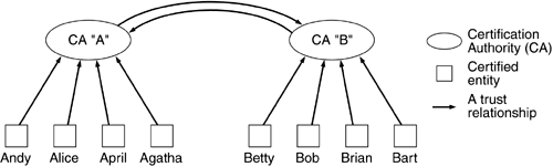
The type of PKI described above is a simple, single-level type of PKI. Only members of the PKI can authenticate other members of a PKI. If Alice is a member of one PKI and Bob is a member of a different PKI, they cannot authenticate each other. For Alice and Bob to authenticate each other, their separate PKIs must enter into a mutual trust arrangement; they must form a trust model. This arrangement can be a joint exchange of certification authority. The CA of Alice's PKI can sign the certificate of the CA of Bob's PKI and vice versa. Such an arrangement is referred to as cross certification (Figure 12.8). Alice trusts her CA to not use its signature improperly and it signed a certificate bearing the public key and identity of another CA—it certified another CA. The other CA further certified the identity of Bob and issued him a certificate. Alice now has a clear path to verify Bob's certificate and each step on the path represents a trust relationship.
Another trust model that can be used in building a PKI is a hierarchical one. In this model there exists a “root” CA that all entities implicitly trust. But instead of having a flat PKI where this CA issues all certificates, it instead signs the certificates of other certification authorities. These other CAs can, in turn, sign the certificates of still more CAs. In this way a hierarchical tree of trust is built (Figure 12.9).
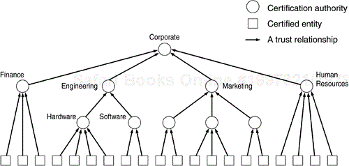
Hierarchical relationships exist naturally, so this model is well suited to adapting a PKI to an organization and not the other way around. For instance, have different departments and those departments can have groups. In this way an engineer working in the security group of the network protocols division of a corporation can have a certificate that is signed by the CA of the security group. The certificate of that CA is signed by the network protocols division CA which can, in turn, be signed by the engineering department CA that is then signed by the corporate CA. Validation of a certificate entails “walking” a chain of certificates until a common trust point—a node on the tree—is reached. To validate the employee's certificate, a member of the human resources department may have to walk the chain all the way back to the corporate CA, while a member of the integrated circuit design team (who is also in the engineering department) may only need to walk as far as the engineering CA.
Certificates cannot last forever. If an employee left a company her certificate should not allow her to authenticate herself as an employee anymore. Therefore, each CA maintains a list of revoked certificates—a Certificate Revocation List, or CRL. This CRL is, ideally, published in an easily available repository or directory. As part of certificate validation (signature checking, chain walking, etc.) the CRL must be checked to determine whether this certificate is current or has been revoked. Obviously, any certificate on the CRL should not be accepted.
An important issue in building a PKI is the problem of the name space. The identity information contained in a certificate could be a name, address, city, and country of residence. Or it could be a name, division, and employee number. Or, if the entity is not even a human being, an IP address. Each CA describes the identity of an entity using information it deems important. What one CA thinks important another may think trivial, perhaps so trivial as to not even mention it. There could even be conflicts in name spaces between CAs.
For any security scheme involving authentication to scale to a reasonable size, some form of PKI must be built. Using preshared keys with IKE works, but the burden of preshared key distribution rapidly becomes onerous as the group grows. Similarly the bureaucracy for securely distributing public keys for use with IKE's other authentication methods would also collapse under its own weight. Clearly, IKE and IPSec need a PKI, but the issues of certificate format, certificate acquisition, trust models, certificate expiry, and revocation, etc., are not part of the IKE and IPSec specifications. That problem was (and still is being) solved by another working group in the IETF, the public key infrastructure (PKIX) working group. The PKIX group has defined an architectural model of a PKI and has developed a series of standards-track RFCs to describe it. The PKIX working group uses the work from other standards bodies (ITU, ANSI) but defines its use for the Internet. For instance, the definition of certain extensions to the X.509 standard are very broad and the PKIX working group has developed a profile for their use in the Internet. This is an on- going task, and as more and more PKIs are deployed, knowledge learned from the experience is translated back into the process as new documents or refinements of existing documents.
A PKI is not a technology solution in and of itself. It is an enabling technology. It is also an investment, and the benefits of it do not immediately outweigh the cost of deployment. Because of this, PKI deployment is a slow task and the number of fully functioning PKIs in existence today is quite small. While the early bird may catch the worm, it's usually not the first person through a mine field that survives, and that sentiment is seen in PKI development. PKIs are complex, and many thorny issues arise when they are built. It's not as easy as just saying, “We're going to use certificates for authentication” (although the amount of times that phrase is used as a complete answer is staggeringly large). As lessons are learned, though, PKIs will become more and more prevalent, thereby enabling the deployment of IKE and IPSec and satisfying the promise of ubiquitous network security on a global scale.
[5] The key distribution protocol itself has been patented by Cisco Systems, Inc. but will be licensed for use in MKMP in a standard, nondiscriminatory manner. The fee, if any, for its use in MKMP will be nominal.