
2Image Acquisition
Image acquisition is the initial step used by computers and electronic equipment to form and treat images. Images reflect the objective world in space, time, and other properties. Therefore, image acquisition captures the spatial, temporal, and other information from a scene.
The sections of this chapter will be arranged as follows:
Section 2.1 introduces several camera imaging models (including few approximate projection models), from simple to complex and from special to general.
Section 2.2 describes some binocular imaging modes, including binocular transversal mode, binocular converging mode, and binocular axial mode.
Section 2.3 discusses some basic concepts of photometry, and then introduces a basic brightness imaging model.
Section 2.4 focuses on the sampling and quantization in image acquisition, as well as spatial resolution and amplitude resolution of images.
2.1Spatial Relationship in Image Formation
Spatial relationship plays an important role in image acquisition. It relates and converts the spatial and temporal information in a scene to the captured image.
2.1.1Coordinate System
In image acquisition, the camera is used to make a perspective projection of the 3-D scene of the objective world onto the 2-D image plane. The projection, from the space point of view, can be described by imaging transformation (also known as geometrical perspective transformation or perspective transformation). Imaging transformation involves the conversion between different spatial coordinate systems. In consideration that the end result of the image acquisition is to obtain digital images being input into the computer, the imaging coordinate systems involved in imaging scene of 3-D space include the following four coordinate systems.
2.1.1.1World Coordinate System
World coordinate system is also known as the real-world coordinate system XYZ, which represents the absolute coordinates of the objective world (it is also called objective coordinate system). General 3-D scenes are using this coordinate system for representation.
2.1.1.2Camera Coordinate System
Camera coordinate system is the coordinate system xyz, which is developed by taking the camera as center (origin) and the camera optical axis as z axis.
2.1.1.3Image Plane Coordinate System
Image plane coordinate system is the coordinate system x′ y′ at the imaging plane of camera. Generally, the xy plane is taken as parallel to the plane of the camera coordinate system, as well as the x-axis and the x′-axis, y-axis and the y′-axis coincides, respectively, so that the origin of the image plane is on the optical axis of the camera.
2.1.1.4Computer Image Coordinate System
Computer image coordinate system is the coordinate system MN that is inside the computer for representing image. The final image is stored by a memory within the computer, so the projection coordinates on image plane needs to be converted to computer image coordinate system.
According to the above mutual relations of several different coordinate systems, several different (camera) imaging model can be formed. In the following, the step-by-step descriptions from simple to complex are provided.
2.1.2Perspective Transformations
Image acquisition includes the projection of a 3-D scene onto a 2-D image in which the perspective projection/transformation plays an important role.
2.1.2.1Projection Model
A model of image capturing by a camera with perspective projection is shown in Figure 2.1. Three coordinate systems are involved: The world coordinate system (X, Y, Z), the camera coordinate system (x, y, z), and the image coordinate system (x′, y′). Here, suppose the camera coordinate system is aligned with the world coordinate system, and the image coordinate system is aligned with the camera coordinate system. This camera position is known as the normal position. The focal length of the camera lens is λ. A 3-D point W(X, Y, Z) is projected onto the point (x, y) = (x′, y′) at the image plane.

According to the properties of similar triangles, the relationship between a 3-D point in the world space and its 2-D projection at the image plane is established by
where the negative signs in front of X and Y indicate the inversion of the image point with respect to the space point. The coordinates of the image point are obtained by
The above projection maps a line in 3-D space onto a line at the image plane (with the exception that the line to be projected is perpendicular to the image plane). A rectangle in 3-D space could be any quadrangle (determined by four points) at the image plane, after the projection. Therefore, such a projection is referred to as a four-point mapping. The transformations in eq. (2.3) and eq. (2.4) are nonlinear as the coordinate values are involved in the division.
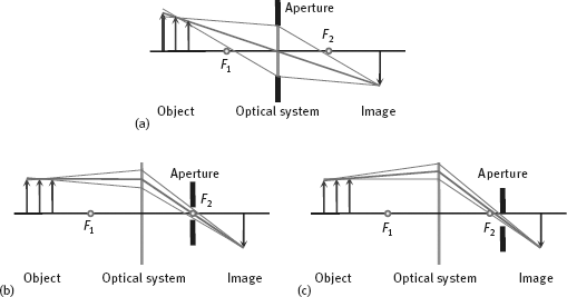
Example 2.1 Telecentric imaging and supercentric imaging
In general standard optical imaging system, the light beams are converged. It has a significant adverse effect for the optical measurement; see Figure 2.2(a). If the position of the object is changing, the image becomes larger when the object is close to the lens and becomes smaller when the object is away from the lens. The depth of the object could not be obtained from the image, unless the object is placed on the known distance, otherwise the measurement error is inevitable.
If the aperture position is moved to the convergence point of parallel light (F2) a telecentric imaging system can be obtained, as shown in Figure 2.2(b). In this case, the main ray (the light beam passing through the center of aperture) is parallel to the optical axis in the object space and the small change of object position would not change the size of the object image. Of course, the farther away the object is from the focus position, the stronger the object is blurred. However, the center of blur disk does not change the position. The disadvantage of telecentric imaging is that the diameter of telecentric lens should reach at least the size of the object to be imaged. Thus, using a telecentric imaging is very expensive for very big object.
If the aperture is put even closer to the image plane than the convergence point of parallel light beams, as in Figure 2.2(c), the main ray becomes the converging lines of space. In contrast to the standard imaging of Figure 2.2(a), the farther the object, the bigger the object looks. This imaging technique is called supercentric imaging. One of its characteristics is that the surface parallel with the optical axis can be seen. In Figure 2.3, three imaging techniques for viewing a thin-walled cylinder along the optical axis are illustrated. The standard imaging can see the cross section and the inner wall, the telecentric imaging can only see the cross section, while the supercentric imaging can see both the cross section and an outer wall (Jähne, 2004).
![]()

2.1.2.2Homogeneous Coordinates
To express these transformations in the form of a linear matrix, which is more convenient for manipulation, the homogeneous coordinates are often used.
The homogeneous coordinates of a point in an XYZ coordinate system are defined as (kX, kY, kZ, k), where k is an arbitrary but nonzero constant. For example, a point in an XYZ coordinate system can be expressed as a vector:
The vector in the homogeneous coordinates is
By defining the matrix of perspective projection as
The perspective projection of Wh is given by
The elements of ch are the camera coordinates in the homogeneous coordinates. They can be converted to Cartesian coordinates by dividing the first three elements of ch by the fourth one
The first two elements of c are just the image coordinates of a 3-D space point (X, Y, Z) after projection.
2.1.2.3Inverse Projection
Inverse projection is used to determine the coordinates of a 3-D point according to its projection on a 2-D image. Following eq. (2.8), this projection can be expressed by
where the inverse projection matrix P–1 is
Now consider a 2-D image point (x′, y′, 0), which can be represented by a homogeneous form as
By integrating eq. (2.12) into eq. (2.10), the coordinates of a 3-D point in homogeneous form are
The corresponding coordinates in a Cartesian system are
It is clear that the Z coordinate value of a 3-D point could not be uniquely determined by the image point (x′, y′), as Z is always zero for any 3-D point. In other words, the image point (x′, y′) now corresponds to all points lying on the line that pass through (x′, y′, 0) and (0, 0, *), as shown in Figure 2.1.
Solving X and Y from eq. (2.3) and eq. (2.4) yields
It is clear that recovering a 3-D point from its projection on an image by inverse perspective transformation is impossible unless its Z coordinate value is known.
2.1.3Approximate Projection Modes
Perspective projection is a precise projection mode (with nonlinear mapping), but the calculation and analysis are relatively complex. In order to simplify the operation, some (linear) approximate projection modes can be used when the object distance is much larger than the scale of the object itself.
2.1.3.1Orthogonal Projection
In the orthogonal projection, the Z-coordinate of the 3-D spatial point is not considered (the information for object distance are lost), which is equivalent to mapping the 3-D spatial point directly/vertically to the image plane in the direction of the optical axis of the camera. Figure 2.4 shows a bar-shaped object projected onto the Y-axis (corresponding to the YZ profile in Figure 2.1) in both orthogonal projection and perspective projection.

The result of orthographic projection shows the true scale of the cross section of the object, while the result of the perspective projection is related to the object distance d. The orthographic projection can be seen as the particular perspective projection in which the focal length λ is infinite, so the projection transformation matrix can be written as
2.1.3.2Weak Perspective Projection
Weak perspective projection (WPP) is an approximation to the perspective projection. In the weak perspective projection, the first step is to make an orthogonal projection to the plane where the mass center of object is located and is parallel to the image plane; the second step is to make a perspective projection to the image plane. The perspective projection of step 2 here can be achieved by means of equal scaling within the image plane. Let the perspective scaling factor be s, then
is the ration of the focal length over the object distance. By considering s, the projection matrix of the weak perspective can be written as
The orthogonal projection in the weak perspective projection does not consider the Z-coordinate of the 3-D space point but also changes the relative position of each point in the projection plane (corresponding to the change of size). This can make a greater impact on object points that have relatively large distance with the optical axis of the camera. It can be proved that the error on image is the first-order infinitesimal of the error on object.
2.1.3.3Paraperspective Projection
Paraperspective projection is also a projection method located between the orthogonal projection and perspective projection (Dean et al., 1995). A schematic of the paraperspective projection is shown in Figure 2.5. In the figure, the world coordinate system coincides with the camera coordinate system, and the focal length of the camera is λ. The image plane intersects the Z-axis perpendicularly at point (0, 0, λ). Point C is the center of mass of the object S, and the distance from the origin in Z direction is d.
Given a projection plane at Z = d and parallel to the image plane, the process of paraperspective projection has two steps:
(1)Given a particular object S (one of the objects in scene), projecting it parallelly to the projection plane, where each projection line is parallel to the line OC (not necessarily perpendicular to the projection plane).
(2)The above projection result on the projection plane is then projected onto the image plane. The projection result on the image plane will be reduced to λ/d (the same as in the weak perspective projection) because the projection plane and the image plane are parallel.
The first step described above takes into account the effects of the pose and perspective, which preserves the relative position of the object points in the projection plane. The second step takes into account the effects of distance and other positions. It can be shown that the image error is the second-order infinitesimal of the object error, so the parallel perspective projection is closer to the perspective projection than the weak perspective projection.
Example 2.2 Comparison of projection modes
The perspective projection mode and its three approximate projection modes are shown together in Figure 2.6 for comparison.
![]()


2.1.4A General Camera Model
In image engineering, image acquisition is accomplished with the help of certain equipment that can capture the radiation and convert it to a signal. A digital camera is one such piece of equipment. A general camera model is described in the following. In addition, the formulas for perspective projection are presented.
2.1.4.1Model Conversion
In the above discussion, the camera coordinate system is supposed to be aligned with the world coordinate system. In a real situation, this assumption is not always applicable. A more general case is depicted in Figure 2.7. In Figure 2.7, the camera coordinate system is separated from the world coordinate system, but the image coordinate system is still aligned with the camera coordinate system. The offset of the center of the camera (the origin of the camera coordinate system) from the origin of the world coordinate system is denoted D = [Dx, Dy, Dz]. The camera has been panned by an angle (the angle between x and X) and tilted by an angle α (the angle between z and Z).

The above general camera model can be generated from the basic model shown in Figure 2.1, using the following consecutive steps:
(1)Displace the camera center from the origin of the world coordinate system.
(2)Pan the x-axis by an angle γ (around the z-axis).
(3)Tilt the z-axis by an angle α (around the x-axis).
Moving the camera with respect to the world coordinate system is equivalent to inversely moving the world coordinate system with respect to the camera. The first step of the displacement of the origin of the world coordinate system to the camera center can be accomplished by the following translation transformation matrix
In other words, a point (Dx, Dy, Dz) whose homogeneous form is Dh will be located at the origin of the world coordinate system after the transformation of TDh.
Further, consider the coincident of coordinate systems. The pan angle γ is the angle between the x- and X-axes, which are parallel in original situation. The rotation about the x-axis by the angle γ can be achieved by rotating the camera around the z-axis with the angle γ counterclockwise, where the rotation transformation matrix is
Similarly, the tilt angle α is the angle between the z- and Z-axes. The rotation about z-axis by the angle α can be achieved by rotating the camera around the x-axis with the angle α counterclockwise, where the rotation transformation matrix is
The above two rotation matrices can be cascaded into a single matrix
2.1.4.2Perspective Projection
According to the above discussion, a 3-D world point in its homogeneous form Wh after perspective projection becomes
where P is defined in eq. (2.7).
By dividing the first two elements of ch by its fourth element, the Cartesian coordinates (x, y) for a 3-D world point W(X, Y, Z) can be obtained by
Example 2.3 Computing image-plane coordinates
Suppose a camera is mounted in a position for surveillance as shown in Figure 2.8. The center of the camera is located at (0, 0, 1), the focal length of the camera is 0.05 m, the pan angle is 135°, and the tilt angle is also 135°. The task is to determine the image coordinates for space point W (1, 1, 0).
According to the above discussion, it has to find the procedure that moves the camera from the normal position in Figure 2.1 to the particular position in Figure 2.8. The three required steps are depicted in Figure 2.9. Figure 2.9(a) shows the normal position of the camera. The first step is to displace the camera out of the origin, as shown in Figure 2.9(b). The second step is to pan the camera by the angle γ around the z-axis, as shown in Figure 2.9(c). The third step is to rotate the camera around the x-axis and tilt it by the angle α relative to the z-axis, as shown in Figure 2.9(d).
Putting all parameters into eq. (2.22) and eq. (2.23), the image coordinate values of the 3-D point W(1, 1, 0) are x = 0 m and y = –0.008837488 m.
![]()


2.1.5Common Imaging Model
In the imaging model that is more general than the abovementioned general camera model, there are two factors to consider in addition to the noncoincidence of the world coordinate system: the camera coordinate system and the image plane coordinate system. First, the camera lens will be distorted in practice, so the imaging position on the image plane will be shifted from the results of perspective projection calculated with the aforementioned formula. Second, the unit of image coordinates used in the computer is the number of discrete pixels in the memory, so the coordinates on the image plane (here, the continuous coordinates are still used) need to be converted to integer. Figure 2.10 shows a very common imaging model with all these factors in mind.
The imaging transformation from the objective scene to the digital image can be viewed by the following four steps (see Figure 2.11) (Tsai, 1987):

where R and T are a 3 × 3 rotation matrix (actually a function of the angles between the axes of the three coordinate axes of the two coordinate systems) and a 1 × 3 translation vector, respectively:
(2)Transformation from the camera 3-D coordinates (x, y, z) to the distortion-free image plane coordinates (x′, y′):
where Rx and Ry represent the radial distortion of the lens. Most of the lens have a certain degree of radial distortion. Although this distortion in general has no large impact on the human eye, it should be corrected in the optical measurement to avoid a greater error. Theoretically, the lens will have two types of distortions, that is, radial distortion and tangential distortion. Since tangential distortion is relatively small, the radial distortion is only to be considered in general industrial machine vision applications (Tsai, 1987). Radial distortion can be expressed as
where
In eq. (2.34) and eq. (2.35), k = k1. The reason for this approximation simplification is that the higher order terms of r in practice are negligible. Therefore, k2 is not considered. According to the principle of physics, the radial distortion of a point in the image is proportional to the distance from this point to the optical axis of the lens (Shapiro and Stockman, 2001).
where, M and N are the numbers of row pixels and column pixels in the computer memory (computer coordinates), respectively; Om and On are the number of rows and columns for the central pixel of the computer memory; Sx is the distance between two adjacent sensors in the x direction (scan line direction), Sy is the distance between two adjacent sensors in the y direction; Lx is the number of sensor elements in the X direction; Mx is the number of samples in a row (number of pixels) of the computer. µ in eq. (2.37) is an uncertainty of image scaling factor depending on the camera. When a CCD camera is used, the image is progressively scanned. The distance between adjacent pixels in the y′ direction is also the distance between the adjacent CCD sensor elements. However, in the x′ direction, certain uncertainties will be introduced due to the time difference between the image acquisition hardware and the camera scanning hardware, or the scanning time inaccuracies of camera itself. These uncertainties can be described by introducing uncertainty of image scaling factors.