

Initial configuration
This chapter describes the initial configuration of the IBM SAN Volume Controller systems, provides step-by-step instructions about how to do the initial setup, and defines the base settings of the system, which are done during the implementation phase before volumes are created and provisioned.
This chapter includes the following topics:
3.1 Prerequisites
|
Note: SAN Volume Controller is installed by an IBM System Services Representative (IBM SSR). You must provide all the necessary information to the IBM SSR by filling out the planning worksheets, which can be found at IBM Documentation and expanding Planning → Planning for hardware → Physical configuration planning of a system → Requirements and guidelines for completing the hardware location chart.
After the IBM SSR completes their task, continue the setup by following the instructions in 3.3, “System setup” on page 89.
|
Before initializing and setting up the IBM SAN Volume Controller, ensure that the following prerequisites are met:
•The physical components fulfill all the requirements and are correctly installed, including:
– The control enclosures are physically installed in the racks.
– The Ethernet and Fibre Channel (FC) cables are connected.
– The expansion enclosures, if available, are physically installed and attached to the control enclosures that will use them.
– The SAN Volume Controller nodes and optional expansion enclosures are powered on.
|
Note: IBM SAN Volume Controller nodes need plenty of time to charge the batteries. How long it takes to recharge depends on how long it was waiting idle in stock and not production. You cannot start the nodes without a fully charged battery.
|
•The web browser that is used for managing the system is supported by the management GUI. For the list of supported browsers, see IBM Documentation.
– The IPv4 (or IPv6) addresses that are assigned for the system’s management interfaces:
• The unique cluster IP address, which is the address that is used for the management of the system.
• Unique service IP addresses, which are used to access node service interfaces. You need one address for each node (two per control enclosure).
• The IP subnet mask for each subnet that is used.
• The IP gateway for each subnet that is used.
– The licenses that might be required to use particular functions (depending on the system type):
• Remote Copy (RC)
• External Virtualization
• IBM FlashCopy
• Compression
• Encryption
– Information that is used by a system when performing Call Home functions, such as:
• The company name and system installation address.
• The name, email address, and phone number of the storage administrator whom IBM can contact if necessary.
– (optional) The Network Time Protocol (NTP) server IP address.
– (optional) The Simple Mail Transfer Protocol (SMTP) server IP address, which is necessary only if you want to enable Call Home or want to be notified about system events through email.
– (optional) The IP addresses for Remote Support Proxy Servers, which are required only if you want to use them with the Remote Support Assistance feature.
3.2 System initialization
This section provides step-by-step instructions about how to create the SVC cluster.
To start the initialization procedure, connect a desktop PC or a notebook to the technician port. The technician port is a dedicated 1 Gb Ethernet port at the rear of each of the nodes in the control enclosure. It can be use only to initialize or service the system. It cannot be connected to an Ethernet switch because it supports only a direct connection, and it remains disconnected after the initial setup is done.
The location of a technician port on the SAN Volume Controller 2145-SV1 node is shown in Figure 3-1.

Figure 3-1 Location of the technician port on the SAN Volume Controller 2145-SV1 node
The location of a technician port on the SAN Volume Controller 2145-SV2 and 2145-SA2 nodes is show on Figure 3-2.

Figure 3-2 Location of technician port on SAN Volume Controller 2145-SV2 and 2145-SA2 nodes
The technician port runs an IPv4 DHCP server and it can assign an address to any device that is connected to this port. Ensure that your PC or notebook Ethernet adapter is configured to use a DHCP client if you want the IP to be assigned automatically. If you prefer not to use DHCP, you can set a static IP on the Ethernet port from the 192.168.0.x/24 subnet; for example, 192.168.0.2 with the netmask 255.255.255.0.
The default IP address of a technician port on a node canister is 192.168.0.1. Do not use this IP address for your PC or notebook.
|
Note: Ensure that the technician port is not connected to the organization’s network. No Ethernet switches or hubs are supported on this port.
|
3.2.1 System initialization process
Before the SAN Volume Controller is initialized, each node of a new system remains in the candidate state and cannot process I/O. During initialization, a cluster is created, which at that moment consists only of one node. All other nodes except the first one must not be initialized, and they are added to the cluster by using a cluster management interface (GUI or CLI) after first one is set up.
You must specify IPv4 or an IPv6 system management addresses, which are assigned to Ethernet port 1 on each node and used to access the management GUI and CLI. After the system is initialized, you can specify other IP addresses.
|
Note: Do not perform the system initialization procedure on more than one node in a system. During initialization, candidate nodes are added automatically. You also can use the management GUI or CLI to add nodes to the system.
|
Complete the following steps to initialize a new system:
1. Connect your PC or notebook to a technician port of any canister of the control enclosure. Ensure that you obtained a valid IPv4 address with DHCP.
2. Open a supported web browser and go to http://install. The browser is automatically redirected to the System Initialization wizard. You can also use the IP address http://192.168.0.1 if you are not automatically redirected.
|
Note: During the system initialization, you are prompted to accept untrusted certificates because the system certificates are self-signed. If you are directly connected to the service interface, there is no doubt about the identity of the certificate issuer, so you can safely accept the certificates.
|
If the system is not in a state that allows initialization, you are redirected to the Service Assistant interface. Use the displayed error codes to troubleshoot the problem.

Figure 3-3 System Initialization: Welcome dialog box
4. A window opens in which two options are presented, as shown in Figure 3-4. Select the first option and click Next.

Figure 3-4 System initialization: Create a system or expand the existing one
If you select As an additional node in an existing system, you are prompted to disconnect from the technician port and use the GUI of an existing system to add new nodes.
5. Enter the management IP address information for the new system, as shown in Figure 3-5. Set the IP address, network mask, and gateway.

Figure 3-5 System Initialization: Management IP
Click Next.
6. A window with restart timer opens. When the timeout is reached, you can click Next to see the final initialization window, as shown in Figure 3-6. Follow the instructions, and browser is redirected to the management IP address to access the system GUI after you click Finish.

Figure 3-6 System initialization: Complete
If you cannot connect to a network that has access to the management IP, you can continue the system setup from any other workstation that can reach it.
3.3 System setup
This section provides instructions about how to define the basic settings of the system by using the system setup wizard.
3.3.1 System setup wizard
After the initialization is complete and you are redirected to a management GUI from your PC or notebook, or you browse to the management IP address of a freshly initialized system from another workstation, you must complete the system setup wizard to define the basic settings of the system.
|
Notes: Consider the following points:
•Experienced users can disable the system setup wizard and complete the configuration manually. However, this method is not recommended for most use cases.
To disable the system setup wizard on a new system, run the following command:
chsystem -easysetup no
•During the setup wizard, you are prompted to change the default superuser password. If the wizard is bypassed, the system blocks the configuration functions until it is changed. All attempts at configuration return the following error:
CMMVC9473E The command failed because the superuser password must be changed before the system can be configured.
•All configuration settings that are done by using the system setup wizard can be changed later by using the system GUI or CLI.
|
The first time that you connect to the management GUI, you are prompted to accept untrusted certificates because the system certificates are self-signed.
If your company policy requests certificates that are signed by a trusted certificate authority (CA), you can install them after you complete the system setup. For more information about how to perform this task, see 3.5.1, “Configuring secure communications” on page 112.
To complete the system setup wizard, complete the following steps:
1. Log in to system GUI. Until the wizard is complete, you can use only superuser account, as shown in Figure 3-7. Click Sign in.
|
Note: The default password for the superuser account is passw0rd (with the number zero and not the capital letter O). The default password must be changed by using the system setup wizard or after the first CLI login. The new password cannot be set to the default one.
|

Figure 3-7 System setup: Logging in for the first time

Figure 3-8 System setup: Welcome
3. The system automatically adds nodes that are connected and available in the Candidate status to the cluster. This task might take few minutes.
4. Carefully read the license agreement, select I agree with the terms in the license agreement if you want to continue the setup, as shown in Figure 3-9 on page 91. Click Next.

Figure 3-9 System setup: License agreement
5. Enter a new password for the superuser, as shown in Figure 3-10. A valid password is 6 - 64 characters long and it cannot begin or end with a space. Also, the password cannot be set to match the default password. For more information, see 3.5.2, “Configuring password policies” on page 114. Click Apply and then, Next.

Figure 3-10 System setup: Changing the password for the superuser
|
Note: All configuration changes that are done with the system setup wizard are applied immediately, including the password change.
|
6. Enter the name that you want to give the new system, as shown on Figure 3-11. Click Apply and then Next.
Avoid using an underscore (_) in a system name. While permitted here, it is not allowed in domain name server (DNS) short names and fully qualified domain names (FQDNs), so such naming might cause confusion and access issues. The following characters can be used: A - Z, a - z, 0 - 9, and - (hyphen).

Figure 3-11 System setup: Setting the system name
|
Note: In a 3-Site replication solution, ensure that the system name is unique for all three clusters to prepare the Spectrum Virtualize clusters at Master, AuxNear, and AuxFar sites to work. System names must remain different through the life of the 3-Site configuration.
|
7. Enter the number of licensed SCUs or licensed capacity for each function, as shown in Figure 3-12.
SAN Volume Controller uses differential and capacity-based licensing. For External Virtualization and compression, differential licensing offers different pricing rates for different types of storage, and it is based on the number of Storage Capacity Units (SCUs) that are purchased. For other licensed functions, the system supports capacity-based licensing.
Make sure that the numbers you enter here match the numbers in your license authorization papers.
When done, click Apply and then Next.
|
Note: Encryption uses a key-based licensing scheme, and it is activated later in the wizard.
|

Figure 3-12 System setup: Setting the system licenses
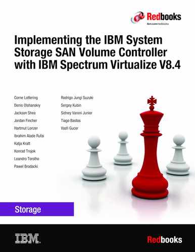
8. Enter the date and time settings. In the example that is shown in Figure 3-13, the date and time are set by using an NTP server. Generally, use an NTP server so that all of your storage area network (SAN) and storage devices have a common time stamp. This practice facilitates troubleshooting and prevents time stamp-related errors if you use a key server as an encryption key provider.
If you choose to manually enter these settings, you are prompted to input the date, time, and time zone, or you can take those settings from your web browser. You cannot use a 24-hour clock system here, but you can switch to it later by using the system GUI.
When the data is set, click Apply and then Next.
Figure 3-13 System setup: Setting the date and time
9. Select whether the encryption feature was purchased for this system, as shown in Figure 3-14.

Figure 3-14 System setup: Encryption activation
If encryption is not planned at this moment, select No and then, click Next. You can enable this feature later, as described in Chapter 12, “Encryption” on page 715.
If you purchased the encryption feature, you are prompted to activate your license manually or automatically. The encryption license is key-based and required for each control enclosure.
You can use automatic activation if the PC or notebook that you use to connect to the GUI and run the system setup wizard has internet access. If no internet connection is available, use manual activation and follow the instructions. For more information, see Chapter 12, “Encryption” on page 715.
After the encryption license is activated, you see a green check mark next to the node serial number. After all the nodes show that the encryption is licensed, click Next.
10. Set up the Call Home functions, as shown in Figure 3-15. With Call Home enabled, IBM automatically opens problem reports and contacts you to verify whether replacement parts are required.

Figure 3-15 System setup: Call Home methods
|
Note: It is a best practice to configure Call Home and keep it enabled if your system is under warranty or if you have a hardware maintenance agreement.
|
An IBM SSR configures Call Home when performing cluster initialization. You need to only check whether all the entered data is correct.
The system supports two methods of sending Call Home notifications to IBM:
– Cloud Call Home.
– Call Home with email notifications.
Cloud Call Home is the default and preferred option for a system to report event notifications to IBM Support. With this method, the system uses RESTful APIs to connect to an IBM centralized file repository that contains troubleshooting information that is gathered from customers. This method requires no extra configuration.
The system also can be configured to use email notifications for this purpose. If this method is selected, you are prompted to enter the SMTP server IP address.
If both methods are enabled, Cloud Call Home is used, and the email notifications method is kept as a backup.
For more information about setting up Call Home, including Cloud Call Home, see Chapter 13, “Reliability, availability, and serviceability, and monitoring and troubleshooting” on page 777.
If either of these methods is selected, the system location and contact information must be entered. This information is used by IBM to provide technical support. All fields in the form must be populated. In this step, the system also verifies that it can contact the Cloud Call Home servers, as shown in Figure 3-16.

Figure 3-16 System setup: System location
After clicking Next, you can provide business-to-business contact information that IBM Support uses to contact a person who manages this machine if it is necessary, as shown in Figure 3-17.

Figure 3-17 System setup: Contact information
If the Email notifications option was selected, you are prompted to enter the details for the email servers to be used for Call Home. Figure 3-18 shows an example. You can click Ping to verify that the email server is reachable over the network. Click Apply and then, click Next.

Figure 3-18 System setup: Email servers
11. IBM SAN Volume Controller systems can be used with IBM Storage Insights, which is an IBM cloud storage monitoring and management tool. During this setup phase, the system tries to contact the IBM Storage Insights web service. If it is available, you are prompted to sign up, as shown in Figure 3-19.

Figure 3-19 System setup: IBM Storage Insights
If a connection cannot be established, you are prompted to add the system that you are currently working on to the IBM Storage Insights setup manually, as shown in Figure 3-20.

Figure 3-20 System setup: IBM Storage Insights
For more information about IBM Storage Insights, see Chapter 13, “Reliability, availability, and serviceability, and monitoring and troubleshooting” on page 777.
12. After you click Next, if you enabled at least one Call Home method, the Support Assistance configuration window opens, as shown in Figure 3-21 on page 98. The Support Assistance function requires Call Home, so if it is disabled, Support Assistance cannot be used.
With the Support Assistance feature, you allow IBM Support to perform maintenance tasks on your system while an IBM SSR is onsite. The IBM SSR can log in locally with your permission and a special user ID and password so that a superuser password does not need to be shared with the IBM SSR.
You can also enable Support Assistance with remote support to allow IBM Support personnel to log in remotely to the machine with your permission through a secure tunnel over the internet.
For more information about the Support Assistance feature, see Chapter 13, “Reliability, availability, and serviceability, and monitoring and troubleshooting” on page 777.

Figure 3-21 System setup: Support Assistance
If you allow remote support, you are given the IP addresses and ports of the remote support centers and an opportunity to provide proxy server details (if required) to allow the connectivity, as shown in Figure 3-22. Also, you can allow remote connectivity at any time or only after obtaining permission from the storage administrator.

Figure 3-22 System setup: Support Centers
13. On the Summary page, the settings that were set by the system setup wizard are shown. If corrections are needed, you can return to a previous step by clicking Back. Otherwise, click Finish to be redirected to a system GUI.
After the wizard completes, your system consists only of the nodes that were available as candidates: powered off, connected to SAN and zoned together. If you have nodes, you must add them to complete system setup. For more information about how to add a node, see 3.4.2, “Adding a node or hot spare node” on page 102.
If you have no more nodes to add to this system, the system setup process is complete. All the mandatory steps of the initial configuration are done. If required, you can configure other global functions, such as system topology, user authentication, or local port masking, before configuring the volumes and provisioning them to hosts.
3.4 Base configuration
Tasks that are listed in this section are used to define global system configuration settings. Often, they are performed during system setup. However, they also can be performed any time later, such as when the system is expanded or the system environment is reconfigured.
3.4.1 Configuring Remote Direct Memory Access clustering
Up to four control enclosures can be joined in an IBM HyperSwap or a standard topology cluster. This subsection describes the configuration steps that must be performed if a system is designed for IP-based Remote Direct Memory Access (RDMA) node-to-node traffic. For FC SAN clustering, no special configuration is required on the system, but the SAN must be set up as described in Chapter 2, “Planning” on page 49.
Prerequisites
Before RDMA clustering is configured, ensure that the following prerequisites are met:
•25 gigabits per second (Gbps) RDMA-capable Ethernet cards are installed in each node.
•RDMA-capable adapters in all nodes use the same technology, such as RDMA over Converged Ethernet (RoCE) or internet Wide Area RDMA Protocol (iWARP).
•RDMA-capable adapters are installed in the same slots across all the nodes of the system.
•Ethernet cables between each node are connected correctly.
•The network configuration does not contain more than two hops in the fabric of switches. The router must not be placed between nodes that use RDMA-capable Ethernet ports for node-to-node communication.
•The negotiated speeds on the local and remote adapters are the same.
•The local and remote port virtual local area network (VLAN) identifiers are the same. All the ports that are used for node-to node communication must be assigned to one VLAN ID, and ports that are used for host attachment must have a different VLAN ID. If you plan to use VLAN to create this separation, you must configure VLAN support on the all the Ethernet switches in your network before you define the RDMA-capable Ethernet ports on nodes in the system. On each switch in your network, set the VLAN to Trunk mode and specify the VLAN ID for the RDMA-ports that will be in the same VLAN.
•A minimum of two dedicated RDMA-capable Ethernet ports are required for node-to-node communications to ensure best performance and reliability. These ports must be configured for inter-node traffic only and must not be used for host attachment, virtualization of Ethernet-attached external storage, or IP replication traffic.
•A maximum of four RDMA-capable Ethernet ports per node are allowed for node-to-node communications.
Configuration process
To enable RDMA clustering, IP addresses must be configured on each port of each node that is used for node-to-node communication. Complete the following steps:
1. Connect to a Service Assistant of a node by going to https://<node_service_IP>/service and clicking Change Node IP, as shown in Figure 3-23.

Figure 3-23 Node IP address setup for RDMA clustering
Figure 3-23 shows that ports 1 - 3 do not show any RDMA type, so they cannot be used for node-to-node traffic. Ports 4 and 5 show RDMA type RoCE, so they can be used.
2. Hover your cursor over a tile with a port and click Modify to set the IP address, netmask, gateway address, and VLAN ID for a port. The IP address for each port must be unique and cannot be used anywhere else on the system. The VLAN ID for ports that are used for node-to-node traffic must be the same on all nodes. When the required information is entered, click Save and verify that the operation completed successfully, as shown in Figure 3-24. Repeat this step for all ports that you intend to use for node-to-node traffic, with a minimum of two and a maximum of four ports per node.

Figure 3-24 Node IP addresses configured
To list and change the node IP configuration by using the CLI, run the sainfo lsnodeip and satask chnodeip commands, as shown in Example 3-1.
Example 3-1 Setting IP addresses for node-to-node connectivity
IBM_2145::superuser>sainfo lsnodeip
port_id rdma_type port_speed vlan link_state state node_IP_address
1 1Gb/s active unconfigured
2 1Gb/s active unconfigured
3 1Gb/s active unconfigured
4 RoCE 25Gb/s active unconfigured
5 RoCE 25Gb/s active unconfigured
IBM_2145::superuser>satask chnodeip -ip 10.0.99.12 -gw 10.0.99.1 -mask 255.255.255.0 -port_id 4
IBM_2145::superuser>satask chnodeip -ip 192.168.59.11 -gw 192.168.59.1 -mask 255.255.255.0 -port_id 5
IBM_2145::superuser>sainfo lsnodeip
port_id rdma_type port_speed vlan link_state state node_IP_address
1 1Gb/s active unconfigured
2 1Gb/s active unconfigured
3 1Gb/s active unconfigured
4 RoCE 25Gb/s active configured 10.0.99.12
5 RoCE 25Gb/s active configured 192.168.59.11
3. Some environments might not include a stretched layer 2 subnet. In such scenarios, a layer 3 network such as in standard topologies or long-distance RDMA node-to-node HyperSwap configurations is applicable. To support the layer 3 Ethernet network, use the unicast discovery method for RDMA node-to-node communication. This method relies on unicast-based fabric discovery rather than multicast discovery.
To configure unicast discovery, see the information about the satask addnodediscoverysubnet, satask rmnodediscoverysubnet, or sainfo lsnodediscoverysubnet commands in IBM Documentation. You can also configure discovery subnets by using the Service Assistant interface menu option Change Node Discovery Subnet, as shown in Figure 3-25.

Figure 3-25 Setting the node discovery subnet
4. After the IP addresses are configured on all nodes in a system, run the sainfo lsnodeipconnectivity command or use the Service Assistant GUI menu Ethernet Connectivity to verify that the partner nodes are visible on the IP network, as shown in Figure 3-26 on page 102. If necessary, troubleshoot connection problems by running the ping and sainfo traceroute commands.

Figure 3-26 Node-to-node Ethernet connectivity
When all the nodes that are joined to the cluster are connected, the enclosure can be added to the cluster.
3.4.2 Adding a node or hot spare node
This procedure is the same whether you are configuring the system for the first time or expanding it later. The same process is used to add a node to an I/O group, or a hot spare node.
Before beginning this process, ensure that the new control enclosure is correctly installed and cabled to the existing system. For FC node-to-node communication, verify that correct the SAN zoning is set. For node-to-node communication over RDMA-capable Ethernet ports, ensure that the IP addresses are configured and a connection between nodes can be established.
To add a node to the system, complete the following steps:
1. In the GUI, select Monitoring → System. When a new enclosure is detected by a system, the Add Node button appears on the System - Overview window next to System Actions, as shown in Figure 3-27.

Figure 3-27 Add Node button
|
Note: If the Add Node button does not appear, review the installation instructions to verify that the new node is connected and set up correctly.
|
2. Click Add Node. A form that you can use to assign nodes to I/O groups opens, as shown in Figure 3-28. To light the Identify light-emitting diode (LED) on a node, click the LED icon that is next to a node name. When the required node (or nodes) is assigned, click Next.

Figure 3-28 Assigning a node
3. Review the summary in the next window and click Finish to add the node or nodes to the system.
|
Note: When a node is added, the software version running on it is upgraded or rolled backed to match the cluster software version. This process can take up to 30 minutes or more, and the node is added only after this process completes.
|
4. After the node is successfully added to the system, a success message appears. Click Close to return to the System Overview window and check that new node is visible and available for management.
To perform the same procedure by using a CLI, complete the following steps. For more information about the detailed syntax for each command, see IBM Documentation:
1. When adding nodes, check for unpopulated I/O groups by running lsiogrp. Each complete I/O group has two nodes. Example 3-2 shows that only io_grp0 has nodes, so a new control enclosure can be added to io_grp1.
Example 3-2 Listing I/O groups
IBM_2145:ITSO-SVC:superuser>lsiogrp
id name node_count vdisk_count host_count site_id site_name
0 io_grp0 2 0 0
1 io_grp1 0 0 0
2 io_grp2 0 0 0
3 io_grp3 0 0 0
4 recovery_io_grp 0 0 0
2. To list nodes that are available to add to the I/O group, run the lscnodecandidate command, as shown in Example 3-3.
Example 3-3 Listing the candidate nodes
IBM_2145:ITSO-SVC:superuser>lsnodecandidate
id panel_name UPS_serial_number UPS_unique_id hardware
500507680C000416 KD8P1BP 0000000000000000 DH8
3. Add a node by running the addnode command, as shown in Example 3-4. The command triggers only the process, which starts in background and can take up to 30 minutes or more.
Example 3-4 Adding a node as a spare
IBM_2145:ITSO-SVC:superuser>addnode -panelname KD8P1BP -spare
Example 3-5 shows same command, but used to add a node to an I/O group io_grp1.
Example 3-5 Adding a node to an I/O group
IBM_2145:ITSO-SVC:superuser>addnode -panelname KD8P1BP -name node3 -iogrp 1
3.4.3 Changing the system topology
IBM SAN Volume Controller supports two multi-site topologies: HyperSwap and Enhanced Stretched Cluster (ESC). For each I/O group in the system, the “stretched” topology has one node on one site and one node on the other site. The HyperSwap topology places both nodes of an I/O group at the same site. Both topologies enable full configuration of the highly available (HA) volumes through a single point of configuration.
If your solution is designed for ESC or HyperSwap, use the guidance in this section to configure your topology for either solution.
For a list of requirements for a HyperSwap or ESC configuration, see IBM Documentation and expand Configuring → Configuration details → Stretched system configuration details and HyperSwap system configuration details.
To change the system topology, complete the following steps:
1. In the GUI, click Monitoring → System to open the System - Overview window. Click System Actions and select Modify System Topology, as shown in Figure 3-29.

Figure 3-29 Starting the Modify System Topology wizard
2. The Modify Topology wizard welcome window opens. Click Next. You are prompted to change the default site names, as shown in Figure 3-30. The site names can indicate, for example, building locations for each site, or other descriptive information.

Figure 3-30 Assigning site names
3. Select HyperSwap System or Stretched System for the topology, and assign I/O groups to the sites. Click the marked icons in the center of the window to swap site assignments, as shown in Figure 3-31. Click Next.

Figure 3-31 Specifying the system topology
4. If any host objects or back-end storage controllers are configured, you must assign a site for each of them. Right-click the object and click Modify Site, as shown in Figure 3-32.

Figure 3-32 Assigning controllers to the sites
5. If you are configuring HyperSwap topology, set the maximum background copy operations bandwidth between the sites. Background copy is the initial synchronization and any subsequent resynchronization traffic for HyperSwap volumes. Use this setting to limit the impact of volume synchronization to host operations. You can also set it higher during the initial setup (when there are no host operations on the volumes yet), and set it lower when the system is in production.
As shown in Figure 3-33, you must specify the total bandwidth between the sites in megabits per second (Mbps) and what percentage of this bandwidth that can be used for background copying. Click Next.
An ESC topology system does not require this setting.

Figure 3-33 Setting the bandwidth between the sites for a HyperSwap topology
6. Review the summary and click Finish. The wizard starts implementing changes to migrate the system to the topology.
When you later add a host or back-end storage controller objects, the GUI prompts you to set an object site during the creation process.
3.4.4 Configuring quorum disks or applications
Quorum devices are required for a system to hold a copy of important system configuration data. A managed disk (MDisk) from FC-attached external back-end storage or a special application that is connected over an IP network can work as a quorum device.
One of these items is selected for the active quorum role, which is used to resolve failure scenarios where half the nodes on the system become unavailable or a link between enclosures is disrupted. The active quorum determines which nodes can continue processing host operations and to avoid a “split brain” condition, which happens when both halves of the system continue I/O processing independently of each other.
For systems with a standard topology, quorum devices are automatically assigned from a managed MDisk. No special configuration actions are required. Optionally, an IP quorum device can be configured to provide extra redundancy.
For ESC and HyperSwap topology systems, an active quorum device must be on a third, independent site. Due to the costs that are associated with deploying a separate FC-attached storage device on a third site, an IP-based quorum device can be used for this purpose.
A stretched or HyperSwap system can be configured without a quorum device at a third site. If there is no third site, then quorum must be configured to select a site to always win a tie-breaker. If there is a loss of connectivity between the sites, then the site that is configured as the winner continues operating and processing I/O requests and the other site stops until the fault is fixed. If there is a site outage at the wining site, then the system stops processing I/O requests until this site is recovered or the manual quorum override procedure is used.
Creating and installing an IP quorum application
To create and install an IP quorum application, complete the following steps:
1. Select System → Settings → IP Quorum to download the IP quorum application, as shown in Figure 3-34. If you are using IPv6 for management IP addresses, the Download IPv6 Application button is available and the IPv4 option is disabled.

Figure 3-34 Download IPv4 quorum button
2. After you click Download..., and a window opens, as shown in Figure 3-35 on page 108. It provides an option to create an IP application that is used for tie-breaking only, or an application that can be used as a tie-breaker and to store recovery metadata.

Figure 3-35 Download IP quorum application window
An application that does not store recovery metadata requires less channel bandwidth for a link between the system and the quorum application, which can be a decision-making factor for using a multi-site HyperSwap system.
For a full list of IP quorum app requirements, see IBM Documentation and expand Configuring → Configuration details → Configuring quorum → IP quorum application configuration.
3. After you click OK, the ip_quorum.jar file is created. Save the file and transfer it to a supported AIX, Linux, or Windows host that can establish an IP connection to the service IP address of each system node. Move it to a separate directory and start the app, as shown in Example 3-6.
Example 3-6 Starting the IP Quorum app on the Windows operating system
C:IPQuorum>java -jar ip_quorum.jar
=== IP quorum ===
Name set to null.
Successfully parsed the configuration, found 4 nodes.
....
|
Note: Add the IP quorum application to the list of auto-started applications at each start or restart or configure your operating system to run it as an auto-started service in the background. The Server which runs the IP Quorum must be in the same subnet as the IBM SAN Volume Controller. You can have a total number of 5 IP Quorums
|
The IP quorum log file and recovery metadata are stored in the same directory with the ip_quorum.jar file.
4. Check that the IP quorum application is successfully connected and running by verifying its Online status by selecting System → Settings → IP Quorum, as shown in Figure 3-36.

Figure 3-36 IP quorum application that is deployed and connected
Configuring IP quorum mode
On a standard topology system, only the Standard quorum mode is supported. No additional configuration is required. On an ESC or HyperSwap topology, you can configure different tie-breaker scenarios (a tie occurs when exactly half of the nodes that were previously a member of the system are present):
•If the quorum mode is set to Standard, both sites have an equal chance to continue working after the tie-breaker.
•If the quorum mode is set Preferred, during a disruption, the system delays processing tie-breaker operations on non-preferred sites, leaving more time for the preferred site to win. If during an extended period a preferred site cannot contact the IP quorum app (for example, if it is destroyed), a non-preferred site continues working.
•If the quorum mode is set to Winner, the selected site always is the tie-breaker winner. If the winner site is destroyed, the remaining site can continue operating only after manual intervention.
The Preferred and Winner quorum modes are supported only with an IP quorum. For a FC-attached active quorum MDisk, only Standard mode is possible.
To set a quorum mode, select System → Settings → IP Quorum and click Quorum Setting. The Quorum Setting window opens, as shown in Figure 3-37.

Figure 3-37 Changing the quorum mode
3.4.5 Configuring the local Fibre Channel port masking
With FC port masking, you control the usage of FC ports. By applying a mask, you restrict node-to-node communication or FC RC traffic on selected ports.
To decide whether your system must have port masks configured, see 2.6.8, “Port designation recommendations” on page 59.
To set the FC port mask by using the GUI, complete the following steps:
1. Select System → Network → Fibre Channel Ports. In a displayed list of FC ports, the ports are grouped by a system port ID. Each port is configured identically across all nodes in the system. You can click the arrow next to the port ID to expand a list and see which node ports (N_Port) belong to the selected system port ID and their worldwide port names (WWPNs).
2. Right-click a system port ID that you want to change and select Modify Connection, as shown in Figure 3-38.

Figure 3-38 Applying a port mask by using a GUI
By default, all system ports can send and receive traffic of any kind:
•Host traffic
•Traffic to virtualized back-end storage systems
•Local system traffic (node-to-node)
•Partner system (remote replication) traffic
The first two types are always allowed, and you can control them only with SAN zoning. The other two types can be blocked by port masking. In the Modify Connection dialog box, as shown in Figure 3-39 on page 111, you can choose which type of traffic that a port can send.
Any A port can work with all four types.
Local Remote replication traffic is blocked on this port.
Remote Blocks local node-to-node traffic.
None Both local and remote systems traffic, but there is still system to host and system to back-end storage communication.

Figure 3-39 Modify Connection dialog box
Port masks can also be set by using the CLI. Local and remote partner port masks are internally represented as a string of zeros and ones. The last digit in the string represents port one. The previous digits represent ports two, three, and so on. If the digit for a port is set to “1”, the port is enabled for the specific type of communication. If it is set to “0”, the system does not send or receive traffic that is controlled by a mask on the port.
To view the current port mask settings, run the lssystem command, as shown in Example 3-7. The output shows that all system ports allow all kinds of traffic.
Example 3-7 Viewing the local port mask
IBM_2145:ITSO-SVC:superuser>lssystem |grep mask
local_fc_port_mask 1111111111111111111111111111111111111111111111111111111111111111
partner_fc_port_mask 1111111111111111111111111111111111111111111111111111111111111111
To set the local or remote port mask, run the chsystem command. Example 3-8 shows the mask setting for a system with four FC ports on each node and that has RC relationships. Masks are applied to allow local node-to-node traffic on ports 1 and 2, and replication traffic on ports 3 and 4.
Example 3-8 Setting a local port mask by running the chsystem command
IBM_2145:ITSO-SVC:superuser>chsystem -localfcportmask 0011
IBM_2145:ITSO-SVC:superuser>chsystem -partnerfcportmask 1100
IBM_2145:ITSO-SVC:superuser>lssystem |grep mask
local_fc_port_mask 0000000000000000000000000000000000000000000000000000000000000011
partner_fc_port_mask 0000000000000000000000000000000000000000000000000000000000001100
The mask is extended with zeros, and all ports that are not explicitly set in a mask have the selected type of traffic blocked.
|
Note: When replacing or upgrading your node hardware, consider that the number of FC ports and their arrangement might be changed. If so, make sure that any configured port masks are still valid for the new configuration.
|
3.5 Configuring management access
The system can be managed by using the GUI and the CLI. Access to the system management interfaces require user authentication. User authentication and the secure communication implementation steps are described in this section.
3.5.1 Configuring secure communications
During system initialization, a self-signed Secure Sockets Layer (SSL) certificate is automatically generated by the system to encrypt communications between the browser and the system. Self-signed certificates generate web browser security warnings and might not comply with organizational security guidelines.
Signed SSL certificates are issued by a trusted CA. A browser maintains a list of trusted CAs that are identified by their root certificate. The root certificate must be included in this list in order for the signed certificate to be trusted.
To see the details of your system certificate, select Settings → Security and click Secure Communications, as shown in Figure 3-40, or run the lssystemcert command.

Figure 3-40 Accessing the Secure Communications window
Based on the security requirements for your system, you can create either a new self-signed certificate or install a signed certificate that is created by a third-party CA.
Generating a self-signed certificate
If a self-signed certificate is expired or its key type does not comply with your company’s security policy, you can regenerate it. To renew a self-signed certificate, complete the following steps:
2. Select Self-signed certificate and enter the details for the new certificate. The “Key type” and “Validity days” are the only mandatory fields.
|
Note: Before re-creating a self-signed certificate, ensure that your browser supports the type of keys that you are going to use for a certificate. See your organization’s security policy to ensure what key type is required.
|
3. Click Update.
You are prompted to confirm the action. Click Yes to proceed. Close the browser, wait approximately 2 minutes, and reconnect to the management GUI.
To regenerate an SSL certificate by using a CLI, run the chsystemcert command, as shown in Example 3-9. Valid values for -keytype are rsa2048, ecdsa384, or ecdsa521.
Example 3-9 Regenerating a self-signed certificate
IBM_2145:ITSO-SVC:superuser>chsystemcert -mkselfsigned -keytype ecdsa521 -validity 365
Configuring a signed certificate
If you company’s security policy requests certificates to be signed by a trusted authority, complete the following steps to configure a signed certificate:
1. Select Update Certificate in the Secure Communications window.
2. Select Signed certificate and enter the details for the new certificate signing request, as shown in Figure 3-41. All fields are mandatory except for the Subject Alternative Name. For the “Country” field, use a two-letter country code. Click Generate Request.

Figure 3-41 Generating a certificate request
3. When prompted, save the certificate.csr file that contains the certificate signing request.
Until the signed certificate is installed, the Secure Communications window shows that an outstanding certificate request exists.
|
Attention: If you must update a field in the certificate request, generate a new request and submit it for signing by the proper CA. However, this process invalidates the previous certificate request and prevents the installation of the signed certificate that is associated with the original request.
|
4. Submit the request to the CA to receive a signed certificate. Notify the CA that you need a certificate (or certificate chain) in base64-encoded Privacy Enhanced Mail (PEM) format.
5. When you receive the signed certificate, select Update Certificate in the Secure Communications window again.
6. Select Signed Certificate and click the folder icon that is next to the Signed Certificate input field of the Update Certificate window, as shown in Figure 3-41 on page 113. Click Update.
7. You are prompted to confirm the action. Click Yes to proceed. After your certificate is installed, the GUI session disconnects. Close the browser window and wait approximately 2 minutes before reconnecting to the management GUI.
8. Reconnect to the GUI and select Settings → Security → Secure Communications. The window that opens should show that you are using a signed certificate, as shown in Figure 3-42.

Figure 3-42 Signed certificate installed
3.5.2 Configuring password policies
A set of options were added to IBM Spectrum Virtualize v8.4.0 or above that allow a securityadmin to create policies for passwords, account lockout, and session timeout. A single system-wide policy applies to all local accounts (session timeouts also apply to remote accounts).
Password creation options
Password creation options can be customized to use the following policies:
|
Note: A new policy does not apply retroactively to existing passwords. However, any new passwords must meet the current policy setting.
|
•Minimum password length (6 - 64 characters)
•Minimum number of uppercase characters (1 - 3)
•Minimum number of lowercase characters (1 - 3)
•Minimum number of special characters (1 - 3)
•Minimum number of digits (1 - 3)
•Password History checking can be enabled.
•0 - 10 previous passwords can be checked.
•Stores the previous password hashes only (for example, no plaintext).
•0: Compare the current password only.
•10: Check that the new password does not match the current password or the 10 passwords that were used before the current password.
•The minimum required password age can be set (0 – 365 days).
A minimum age of 1 means that a user can change a password only once per day (which prevents a user from cycling through the history).
|
Note: The history is not checked when a security admin changes another user’s password. This function is not supported on Flashsystem 5010(E).
|
To set password creation options and password creation rules policies from the GUI, select Settings → Security and then, click Password Policies, as shown in Figure 3-43.

Figure 3-43 Creating password policies for password creation
Password expiration and account lockout
The following options can be used to apply password expiry to passwords:
•Passwords can be set to expire after 0 - 365 days.
•All existing passwords will be set to expire in X days when the setting is first enabled.
•A user with an expired password can log into the system, but cannot run any svctask commands until they change their password.
•An expiry warning can be enabled (0 - 30 days), which warns the user on login that their password expires in X days (only on the CLI on Spectrum Virtualize v8.4).
The security admin can force a user to change their password at any time. The password expires immediately (CLI – individual users, GUI –button to reset all user password):
•Can be used when creating a new user to require a password change on first login.
•Can be used after changing password policy settings.
The following methods can be used to force account locking:
•Manual
The security admin can manually lock and unlock user accounts on the CLI, as shown in Example 3-10.
Example 3-10 Manually locking and unlocking a user account
IBM_2145:IBM Redbook SVC:superuser>svctask chuser -lock bill
IBM_2145:IBM Redbook SVC:superuser>svctask chuser -unlock ted
|
Note: A locked account is not allowed to log in to the system.
|
•Automatic
Accounts can also be locked automatically by setting the maximum number of failed login attempts (0 - 10).
|
Note: The counter is reset on a successful login.
|
By setting the length of time a user is locked out of the system (0 - 10080 minutes [which is 7 days], 0 = indefinite).
Disabling the superuser account and session timeouts, this feature is available only on platforms with a dedicated techport.
|
Note: This feature is not available on FlashSystem 5010(E) and 5030(E).
|
Disabling the superuser account can be done from the GUI or CLI:
•The explicit option to enable superuser locking is shown in Example 3-11.
Example 3-11 To manually enable superuser account locking option
IBM_2145:IBM Redbook SVC:admin>svctask chsecurity -superuserlocking enabled
Changing the system security settings could result in a loss of access to the system via SSH or the management GUI. Refer to the Command Line Interface help for more information about the risks associated with each parameter. Are you sure you wish to continue? (y/yes to confirm) yes
IBM_2145:IBM Redbook SVC:admin>
•The superuser can then be locked, as shown in Example 3-12.
Example 3-12 To manually lock superuser account
IBM_2145:IBM Redbook SVC:admin>svctask chuser -lock superuser
IBM_2145:IBM Redbook SVC:admin>
A good use case is assuming some enterprises have policies that all systems should use remote authority. Therefore, configure remote authority, create a remote security admin, and disable the superuser (now no local accounts can log in to the system).
|
Note: The superuser account is still required for satask actions and recovery actions; for example, T3/T4 recovery. It is automatically unlocked for recovery and must be manually locked again later.
|
Session timeouts can be configured for CLI and GUI sessions:
•Configurable CLI timeout of 5- 240 minutes
•Separate configurable GUI timeout of 5 - 240 minutes
The set of options to govern password expiry, require a password change, account lockouts, disable the superuser account, and session timeouts can be done from the GUI by selecting Settings → Security and clicking Password Policies, as shown in Figure 3-44 on page 118.

Figure 3-44 Creating password polices for password expiration and account lockout
3.5.3 Configuring user authentication
There are two methods of user authentication to control access to the GUI and to the CLI:
•Local user authentication is performed within the SAN Volume Controller system. GUI users authenticate with user name and password. CLI users must provide a user name and a Secure Shell (SSH) public key or a password.
•Remote user authentication allows users to authenticate to the system by using credentials that are stored on an external authentication service. With this feature, you use user credentials and user groups that are defined on the remote service to simplify user management and access, enforce password policies more efficiently, and separate user management from storage management.
Locally administered users can coexist with remote authentication.
User roles and groups
User groups are used to determine what tasks the user is authorized to perform. Each user group is associated with a single role. Roles apply to both local and remote users on the system and are based on the user group to which the user belongs. A local user can belong only to a single group, so the role of a local user is defined by the single group to which that user belongs.
For a list of user roles and their tasks, and a description of a pre-configured user group, see IBM Documentation and expand Product overview → Technical overview → User roles.
Superuser account
Every system has a default user that is called the superuser. It cannot be deleted or modified, except for changing the password and SSH key. The superuser is a local user and cannot be authenticated remotely. The superuser has a SecurityAdmin user role, which has the most privileges within the system.
|
Note: The superuser is the only user that can log in to the Service Assistant interface. It is also the only user that can run sainfo and satask commands through the CLI.
|
The password for superuser is set during the system setup. The superuser password can be reset to its default value of passw0rd by using a procedure that is described in IBM Documentation by expanding Troubleshooting → Resolving a problem → Procedure: Resetting the superuser password.
|
Note: The superuser password reset procedure uses system internal USB ports. Systems with SAN Volume Controller 2145-SV2 and 2145-SA2 nodes can be configured to disable those ports. If the USB ports are disabled and there are no users with the SecurityAdmin role and a known password, the superuser password cannot be reset without replacing the system hardware and deleting the system configuration.
|
Local authentication
A local user is a user whose account is managed entirely on the system. A local user belongs to one user group only, and it must have a password, an SSH public key, or both. Each user has a name, which must be unique across all users in one system.
User names can contain up to 256 printable American Standard Code for Information Interchange (ASCII) characters. Forbidden characters are the single quotation mark ('), colon (:), percent symbol (%), asterisk (*), comma (,), and double quotation marks (“). A user name cannot begin or end with a blank space.
Passwords for local users can be up to 64 printable ASCII characters, but cannot begin or end with a space.
When connecting to the CLI, encryption key authentication is attempted first with the user name and password combination available as a fallback. The SSH key authentication method is available for CLI and file transfer access only. For GUI access, only the password is used.
To add a user that is authenticated without a password by using only an SSH key, select Access → Users by Group, click Add user, and then, click Browse to select the SSH public key for that user, as shown in Figure 3-45 on page 120. The Password field can be left blank. The system accepts public keys that are generated by PuTTY (SSH2), OpenSSH, and RFC 4716-compliant keys that are generated by other clients.

Figure 3-45 Creating a user authenticated by a SSH key
If local authentication is used, user accounts must be created for each system. If you want access for a user on multiple systems, you must define the user in each system.
Remote authentication
A remote user is authenticated by using identity information that is accessible by using the Lightweight Directory Access Protocol (LDAP). The LDAP server must be available for the users to log in to the system. Remote users have their groups defined by the remote authentication service.
Users that are authenticated by an LDAP server can log in to the management GUI and the CLI. These users do not need to be configured locally for CLI access, and they do not need an SSH key that is configured to log in by using the CLI.
If multiple LDAP servers are available, you can configure more than one LDAP server to improve resiliency. Authentication requests are processed by those LDAP servers that are marked as preferred unless the connection fails or a user is not found. Requests are distributed across all preferred servers for load balancing in a round-robin fashion.
|
Note: All LDAP servers that are configured within the same system must be of the same type.
|
If users that are part of a group on the LDAP server are to be authenticated remotely, a user group with an identical name must exist on the system. The user group name is case-sensitive. The user group must also be enabled for remote authentication on the system.
A user who is authenticated remotely is granted permissions according to the role that is assigned to the user group of which the user is a member.
To configure remote authentication by using LDAP, start by enabling remote authentication by completing the following steps:
1. Select Settings → Security, click Remote Authentication, and then click Configure Remote Authentication, as shown in Figure 3-46.

Figure 3-46 Configuring remote authentication
2. Enter the LDAP settings. These settings are not server-specific. They are applied to all LDAP servers that are configured in the system. Extra optional settings are available by clicking Advanced Settings, as shown in Figure 3-47.

Figure 3-47 Configure Remote Authentication settings
The following settings are available:
– LDAP type:
• IBM Security Directory Server (for IBM Security Directory Server).
• Microsoft Active Directory (AD).
• Other (other LDAP v3-capable directory servers, for example, OpenLDAP).
– Security
• LDAP with StartTLS: Select this option to use the StartTLS extension (RFC 2830). It works by establishing a non-encrypted connection with an LDAP server on a standard LDAP port (389), and then performing a TLS handshake over an existing connection.
• LDAPS: Select to use LDAP over SSL and establish secure connections by using port 636.
• None: Select to transport data in clear text format without encryption.
– Service Credentials: Sets a user name and password for administrative binding (the credentials of a user that has the authority to query the LDAP directory). Leave it empty if your LDAP server is configured to support anonymous bind.
For AD, a user name must be in User Principal Name (UPN) format.
– Advanced settings
Speak to the administrator of the LDAP server to ensure that these fields are completed correctly:
• User Attribute
This LDAP attribute is used to determine the user name of remote users. The attribute must exist in your LDAP schema and must be unique for each of your users.
This advanced setting defaults to sAMAaccountName for AD and to uid for IBM Security Directory Server and Other.
• Group Attribute
This LDAP attribute is used to determine the user group memberships of remote users. The attribute must contain either the distinguished name of a group or a colon-separated list of group names.
This advanced setting defaults to memberOf for AD and Other, and to ibm-allGroups for IBM Security Directory Server. For Other LDAP type implementations, you might need to configure the memberOf overlay if it is not in place.
• Audit Log Attribute
This LDAP is an attribute that is used to determine the identity of remote users. When an LDAP user performs an audited action, this identity is recorded in the audit log. This advanced setting defaults to userPrincipalName for AD and to uid for IBM Security Directory Server and the Other type.
3. Enter the server settings for one or more LDAP servers, as shown in Figure 3-48.

Figure 3-48 Configure Remote Authentication: Creating an LDAP server
The following settings are available:
– Preferred
One or more configured LDAP servers can be marked as Preferred. Requests are distributed among these servers, and use only non-preferred servers if all the preferred servers failed.
– IP Address
The IP address of the server.
– Base DN
The distinguished name to use as a starting point for searching for users on the server (for example, dc=itso,dc=ibm,dc=com).
– SSL Certificate
The SSL certificate that is used to securely connect to the LDAP server. This certificate is required only if you chose to use SSL or Transport Layer Security as a security method earlier.
a. Click Browse to select a server certificate. The system accepts certificates in base-64 encoded PEM format. To get a certificate in PEM format from your AD server, select Base-64 Encoded X.509 (.CER) in the MS Windows Certificate Export wizard, as shown in Figure 3-49 on page 124.
.
Figure 3-49 Exporting the AD certificate
|
Note: If your organization is using a tiered CA hierarchy, a server certificate that is exported for use on a system must include all the certificates in a chain. To accomplish this task, export the certificate in MS Windows in .P7B format and use third-party tools (OpenSSL) to convert it to PEM format. Otherwise, the exported certificate will not contain all certificates in the certification path.
|
If you set a certificate and you want to remove it, click the red cross next to Configured.
b. Click the plus and minus signs to add or remove LDAP server records. You can define up to six servers.
c. Click Finish to save the settings.
4. To verify that LDAP is enabled, select Settings → Security → Remote Authentication, as shown in Figure 3-50. You can also test the server connection by selecting Global Actions → Test LDAP connections and verifying that all servers return “CMMVC7075I The LDAP task completed successfully”.

Figure 3-50 Verifying that LDAP is enabled
You can use the Global Actions menu to disable remote authentication and switch to local authentication only.
After remote authentication is enabled, the remote user groups must be configured. You can use the default built-in user groups for remote authentication. However, the name of the default user groups cannot be changed. If the LDAP server contains a group that you want to use and you do not want to create this group on the storage system, the name of the group must be changed on the server side to match the default name. Any user group, whether default or self-defined, must be enabled for remote authentication before LDAP authentication can be used for that group.
To create a user group with remote authentication enabled, complete the following steps:
1. Select Access → Users by Group and click Create User Group. Enter the name for the new group, select the LDAP check box, and choose a role for the users in the group, as shown in Figure 3-51.

Figure 3-51 Creating a user group with remote authentication enabled
2. To enable LDAP for one of the existing groups, select it in the list, select User Group Actions → Properties in the upper right corner, and select the LDAP check box.
3. When you have at least one user group that is enabled for remote authentication, verify that you set up your user group on the LDAP server correctly by checking whether the following conditions are true:
– The name of the user group on the LDAP server matches the one that you modified or created on the storage system.
|
Note: The user group name is case-sensitive.
|
– Each user that you want to authenticate remotely is a member of the LDAP user group that is configured for the system role.
4. To test the user authentication, select Settings → Security → Remote Authentication, and then select Global Actions → Test LDAP Authentication (for an example, see Figure 3-50 on page 124). Enter the user credentials of a user that is defined on the LDAP server and click Test. A successful test returns the message “CMMVC70751 The LDAP task completed successfully”.
A user can log in with their short name (that is, without the domain component) or with the fully qualified user name in the UPN format (user@domain).
..................Content has been hidden....................
You can't read the all page of ebook, please click here login for view all page.