Welcome to Instant LEGO Mindstorm EV3!
At the end of this book you will be able to build and program the new LEGO Mindstorm EV3 to interact with its surroundings. The EV3 will be able to navigate around obstacles, track a crooked line, and maintain its distance from a moving object. You will also learn how to use several sensors with proportional control algorithms.
The EV3 kit contains hundreds of pieces of LEGO bricks. LEGO bricks are high quality plastic parts made with precision moulds, which allow great versatility in the design of robots. The classic LEGO brick was created with a modular spacing that hasn't changed in decades. Because of superior quality and manufacturing processes, the parts I played with, 40 years ago as a boy are fully compatible with the parts made today. The kit contains Technic LEGO bricks consisting of beams, gears, axles, and pins. The EV3 Intelligent Brick contains an ARM9 processor which operates with a Linux based operating system. The EV3 Intelligent Brick has an SDHC Card reader that allows us to make full use of the Linux OS. The extra USB port enables Wi-Fi communication with a dongle. The motors have built-in shaft encoders. Available LEGO sensors include gyro sensors, IR sensors, ultrasonic motion sensors, color sensors, and touch sensors.
LEGO, in collaboration with National Instruments, has developed its own EV3 software which is a visual programming language. The EV3 software is based on LabVIEW (Laboratory Virtual Instrument Engineering Workbench), a visual programming language which is used throughout science, and engineering fields to control instrumentation. LabVIEW is used on probes sent to Mars, to control the world's largest particle accelerator, CERN, and at almost every university in the world for data acquisition and control. When I was first introduced to computer science, I initially described the concept of my programs with a flow chart. LabVIEW and EV3 make this flow chart into an actual programming language. Instead of statements or lines of code, EV3 uses blocks connected by wires representing the flow of data.
Because of the Linux OS, we are able to program the EV3 Intelligent Brick in numerous languages. Other than EV3, the most common languages are RobotC and LabVIEW. I have written this version of the book for the EV3 programming languages and because of the visual nature, it excels at running parallel threads. Most third-party sensor vendors have written downloads for their sensors in EV3, RobotC, NXC, and LabVIEW. In EV3, the downloads are called "MyBlocks", which is the LEGO term for a subroutine. Another advantage of visual language programming is that you can view your entire program at once. When running the debugger, you can actually view which step of the program your robot is executing in real time. Throughout this book we will explore all of the main programming algorithms for programming LEGO robots, including subroutines, loops, if-then statements, variables, constants, and operators. The EV3 language also has a great "scratch page" feature that allows for extensive annotation of the code including videos and images.
The robot in this book is designed with simplicity, balance, and versatility in mind. When I introduce my own students to robotics, I often have them study and/or build complex robots following instructions. I would encourage you to build several of the plans included in your LEGO EV3 set. By following the kit instructions provided by LEGO for over a dozen robots, you will gain a solid introduction to using pins, beams, gears, and motors for building robots. One of the best things about making robots from LEGO is that it allows solution diversity. Over the past 15 years, I have coached students in building dozens of robots with LEGO, TETRIX, VEX, and FIRST platforms. However when designing a robot from scratch, I encourage students to follow the KISS (Keep It Simple Stupid) approach, which I used in the robot design included in this book. You should be able to build the base robot in less than 12 minutes.
By the end of this book you will be familiar with using a proportional controller. In our daily lives, we are surrounded by on-off controllers such as thermostats. Many controllers, such as cruise control on a car, are proportional. The farther you are from your desired speed, the stronger the car will react. When we see a stop sign, our own reactions with the brake pedal are proportional to how far we are from that stop sign and our current speed.
You will build a basic robot with two drive wheels and one manipulator. This robot will be easily customizable with many sensors. It will sense and interact with its surroundings. The robot will move towards a wall, touch the wall, and move its arm. You will find that you can easily modify this design and create your own unique robot.
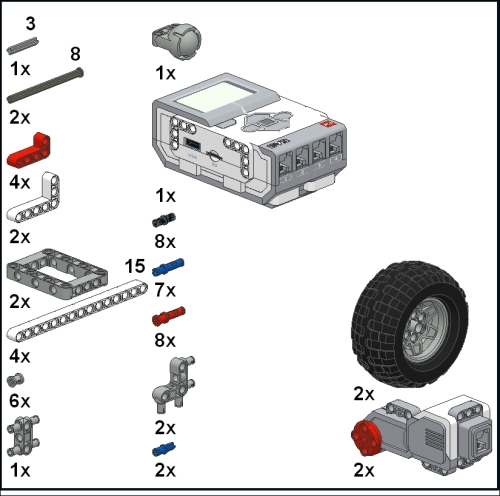
We will first need to gather the following parts from your EV3 set. The parts include several beams, pins, axles, your EV3 Intelligent Brick, two large motors, and some wires. The parts that we will need are shown in the next figure:
You will need to charge up the battery included in your kit or install six AA batteries. You will also need to install the EV3 software on your computer.
We will follow these step by step instructions to build the robot:
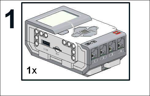
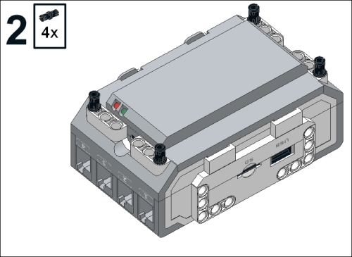
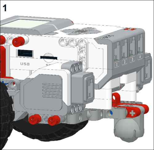
- Start with your EV3 Intelligent Brick which is shown in the next figure:
- Flip your brick over and attach four black friction pins as shown in the next figure:
- Place two white 15 module long beams onto the pins. A module is the unit of length of LEGO bricks and is the spacing between studs on the bricks as shown in the next figure:

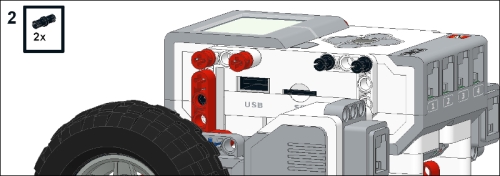
- We will now add four long blue pins, two black pins, and two more beams as shown in the next figure:
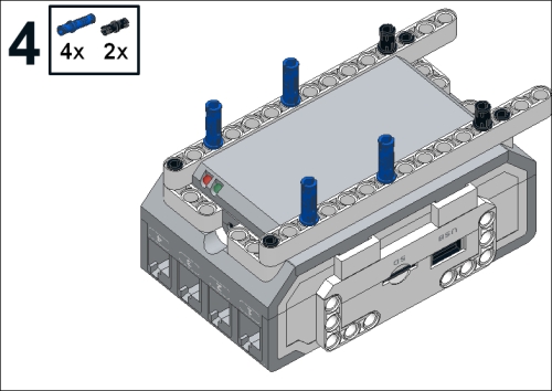
- Make sure that the short end of the blue pins are facing the brick as you can see in the next figure:

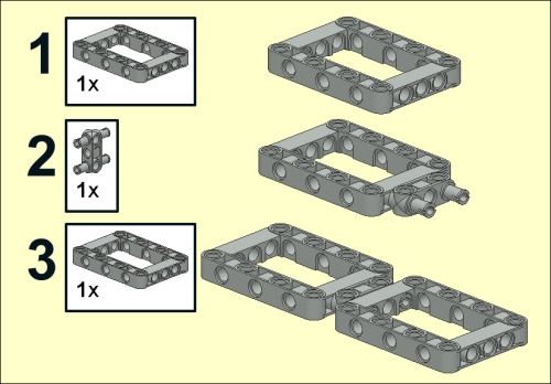
- You will now join two open frame beams with a cross block which forms the chassis of your robot. Building this sub-assembly is broken up into three steps as shown in the next figure:
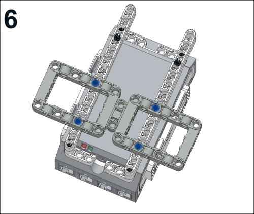
- Place the chassis onto the bottom of your robot as shown in the next figure:
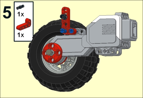
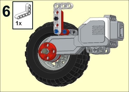
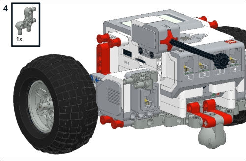
- Next, we are going to build an assembly to hold the caster wheel. You will need the perpendicular connector pin, the caster, a 3-module axle, two red 2x4 bent beams, and a long blue pin. This assembly is divided up into four steps as shown in the next figure:
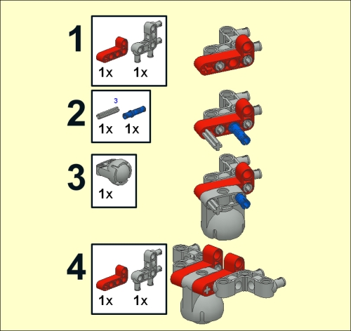
- Attach the caster assembly onto the chassis as shown in the next figure:
- Now we are going to build the right-hand motor assembly. There will be six steps to build the motor assembly. To begin, combine a motor, an 8-module stop-axle, and two bushings as shown in the next figure:

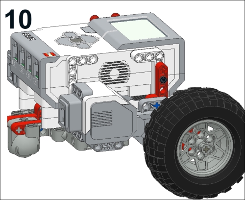
- Attach a hub and tire to the axle as shown in the next figure:
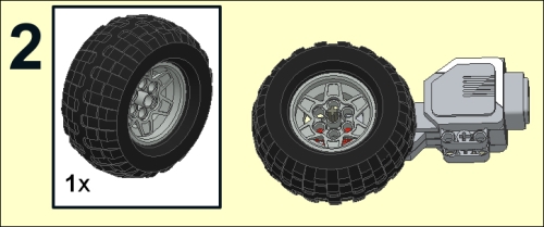
- To secure the tire, place a bushing on the end of the axle as shown in the next figure:
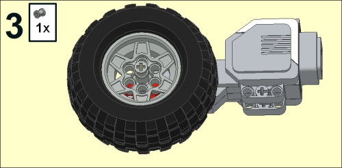
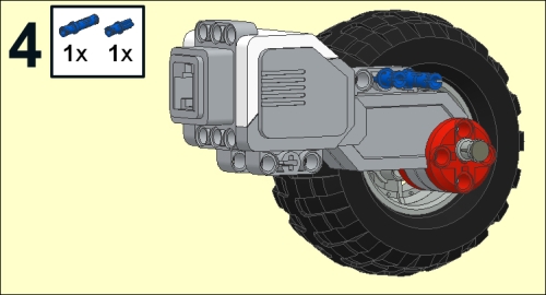
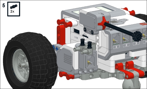
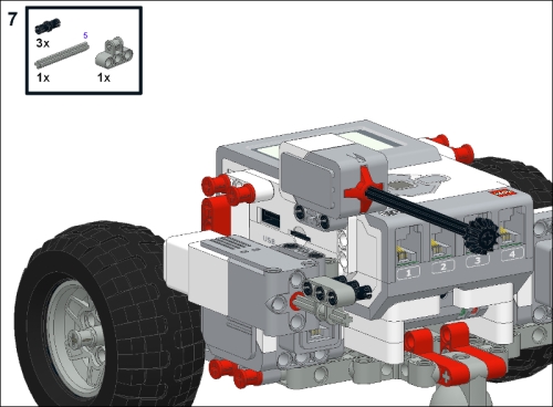
- Insert a blue long pin and a blue axle pin into the motor as shown in the next figure:
- Attach a black pin and red 2x4 bent beam as shown in the next figure:

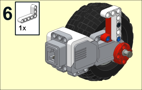
- Attach a white 3x5 bent beam as shown in the next figure:
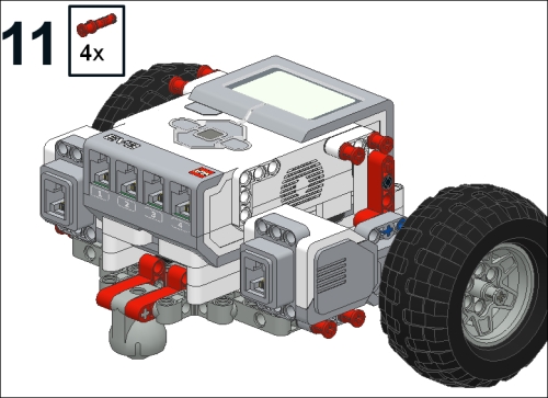
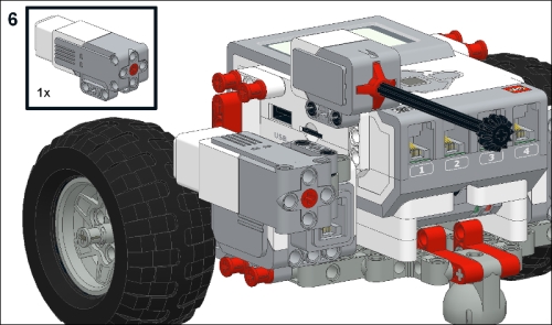
- Attach the right motor assembly to your robot, with four red long pins with stop bushings as shown in the next figure:
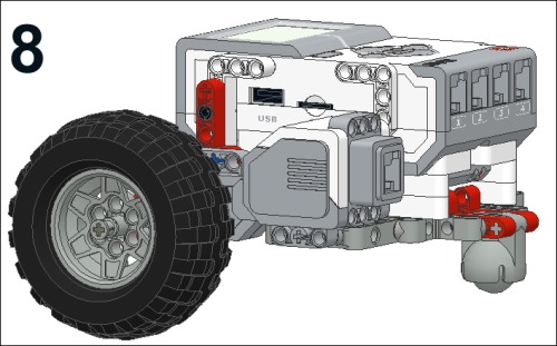
- In the next figure you can see the location of the four red stop bushings:

- Now we will repeat the entire process for the left-hand motor assembly as shown in the next figure:

- Combine a motor, an 8-module stop-axle, and two bushings as shown in the next figure:

- Attach a hub and a tire to the axle. To secure the tire, place a bushing on the end of the axle as shown in the next figure:

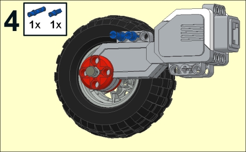
- Insert a blue long pin and a blue axle pin into the motor as shown in the next figure:
- Attach a black pin and red 2x4 bent beam as shown in the next figure:
- Attach a white 3x5 bent beam as shown in the next figure:
- Attach the right motor assembly to your robot with four red long pins with stop bushings as shown in the next figure:
- In the next figure you can see the location of the four red stop bushings as shown:
After attaching wires, our robot will be ready for a test drive. Connect the left-hand motor to Port C on your EV3 brick. Connect the right-hand motor to Port B on your EV3 brick. Turn on your EV3 brick by pressing the dark gray button in the center of the brick.
When you run the EV3 software:
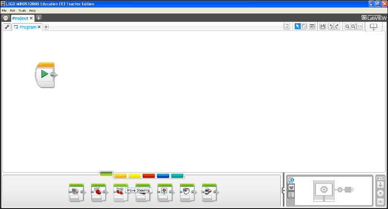
- We are going to write a program to make the robot move forward. Navigate to File | New Project | Program as shown in the next screenshot. This will start up a new program. You could easily start one of the many LEGO tutorials at this point, or perform data logging with an experiment. We will start with a blank sheet.

- You will see several icons at the bottom of the screen on the Programming Palette as shown in the next screenshot:
- Drag a
Move Steeringblock onto the Programming Canvas and place it next to theStartblock as shown in the next screenshot: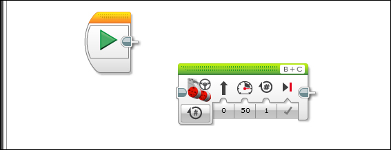
- Using the drop-down menu, set the
Move Steeringblock to On for Rotations. Set the # of rotations of the wheels to 5 as shown in the next screenshot. The motors have built-in shaft encoders which can tell how far they have rotated. The direction can be set to zero, which is straight ahead. The power level can be set to 50 percent. The motors are set to ports B and C.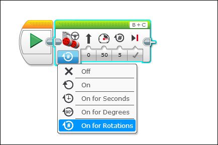
- Although not required, you can set a
Stopblock at the end of the program. Make sure your robot is connected to your computer via the USB cable. You could also connect via Bluetooth. Next, click on the Download and Run button. Your robot should now move backward! You can also run it by clicking on the run icon as shown in the next screenshot:
The robot in this book has a very low center of gravity to prevent tipping. We need this added stability if your robot is going to climb ramps or use an extended arm. One of the greatest features to the medium strength motor is its weight. It is difficult to place large motors high up on your robot without tipping. I have placed the powered drive wheels in the rear with the caster and sensors in the front to allow a quicker response time to the environment. The base robot is simple to build and should be quick to modify for your own designs.
We will now attach sensors and program the robot to interact with its environment using those sensors.
In the next set of steps we will add a touch sensor, a medium size motor, and an ultrasonic motion sensor:
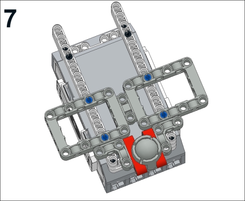
- We will now attach sensors and a medium size motor to the parts of our robot seen in the next figure:
- Insert two black pins on the right side of the robot in order to attach the touch sensor as shown in the next figure:
- Attach the touch sensor as shown in the next figure. You can connect the touch sensor to Port 1 with a wire. You can insert an axle of any length into the touch sensor. Any gear on the end of the axle will make it easier for the sensor to touch things.

- Now we will attach a medium size motor as a manipulator. Insert a perpendicular connector pin into the right-side motor as shown in the next figure:
- Insert two black pins into the connector pin as shown in the next figure:
- Attach the medium size motor to the two black pins as shown in the next figure:
- Insert an axle into the medium size motor. Slide a cross block onto the axle, and insert three black pins into the cross block as shown in the next figure:
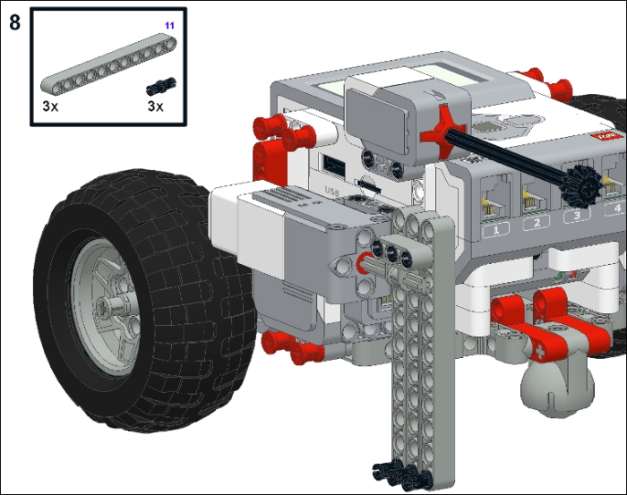
- Attach three grey beams (11 modules long) to the assembly. Insert a black pin into each beam as shown in the next figure:
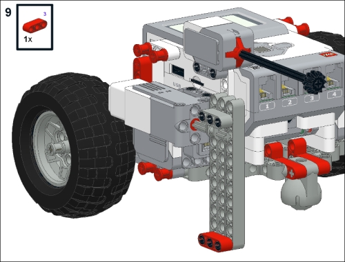
- Attach a beam to the pins to act as a toe for kicking as shown in the next figure. Your robot is now ready to kick small objects. The motor can be wired to Port A.
- Next, we will attach an ultrasonic motion sensor. Insert two black pins onto the left side of the robot as shown in the next figure:
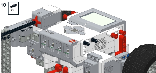
- Attach the motion sensor onto the black pins. Connect the motion sensor to Port 2 with a wire as shown in the next figure:

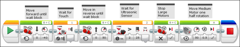
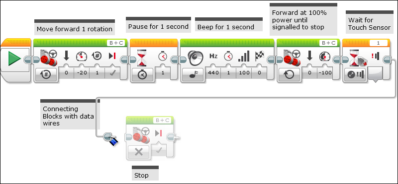
In the following program, the robot will move forward, pause for one second and honk its horn. The Move Steering block moves the robot forward for one rotation of the wheels at 20 percent power. The Wait block will wait for a timing signal of one second. The Sound block can play tones or music from a file. This block will play a tone at 440 Hz for one second at full volume. The next, Move Steering block runs the motors at 100 percent power until signaled to shut down. The next Wait block will wait for a change in signal from the touch sensor. The EV3 will auto-ID the sensors and can tell that the touch sensor is connected to Port 1 if the sensor is plugged in before you place the block on the Programming Canvas. Although the first six blocks are connected by touching each other, you can also connect the blocks with wires as you would for a real instrument. If you click on the Sequence Plug Exit of a block, a wired space between blocks will open up. You can drag this wire to the next command block. This also allows you to make your code two dimensional. One important aspect of visual programming is being able to view your entire code on the screen at one time. These events are illustrated in the following screenshot:
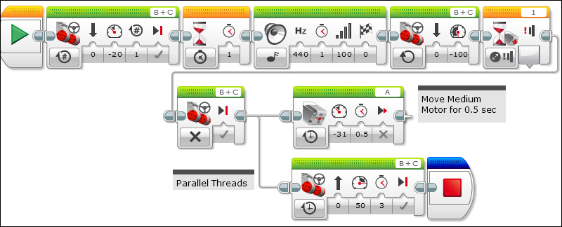
You can also split the wires to run parallel threads in your program. In this case, the wires run to both the Medium Motor block and the Move Steering block. The Medium Motor block will move the kicker foot on our robot for 0.5 seconds at 31 percent power. The Move Steering block will back our robot up for 3 seconds.
We will now use the ultrasonic motion sensor to trigger a command in the program. We can set the ultrasonic sensor to measure distances or to listen to sudden sounds. In this case, we will set the Wait block to measure a distance less than 25 centimeters. In the lower right hand corner of the following screenshot, you can see that EV3 detects the motors in the Ports B and C and the motion sensor in Port 2.
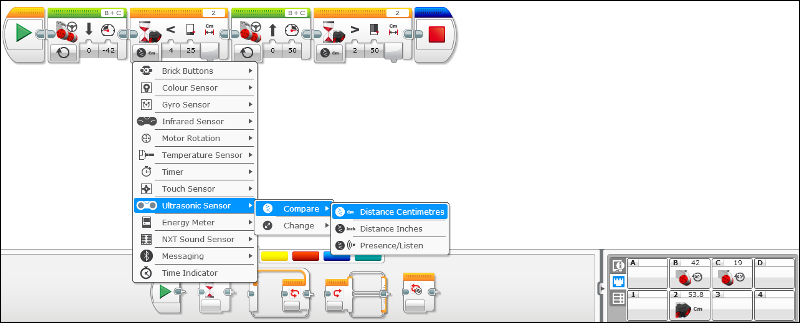
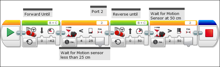
This program will make the robot move forward with a Move Steering block until a signal from the Wait block. The Wait block is triggered by an object at 25 cm. The next Move Steering block will move the robot in reverse until the next Wait block. The next Wait block is triggered when the motion sensor reads 50 cm as shown in the following screenshot: