
Radio Frequency Systems
Abstract
Chapter 12 contains information on basic radio frequency theory, frequency and transmission schemes, components, transmission physics simplified, the effects of power stability and grounding and powering on wireless system reliability, system resets and restores and special power problems related to wireless systems.
Introduction
This chapter contains information on basic radio frequency theory, frequency and transmission schemes, components, transmission physics simplified, the effects of power stability and grounding and powering on wireless system reliability, system resets and restores, and special power problems related to wireless systems.
Basic Radio Frequency Theory
Radio frequency (RF) systems are never as reliable as wired systems, but they are nonetheless useful when wired alternatives are too costly and total quality of service is not required.
Frequencies and Transmission Schemes
Frequencies
Analog AM and FM Frequencies
There have been a variety of different types of RF methods used for security systems throughout the years. Common analog communications have included both AM and FM communications at a variety of frequencies from low kilohertz to gigahertz.
Digital Frequencies
Common frequencies include 900 MHz, 2.4 GHz, 4.9 GHz (public safety), and 5 GHz.
Range
Transmitters and receivers are available at 5.0, 5.8, and 5.2 GHz.
Other Frequencies
Other less used devices operate at 8 GHz, 20 GHz, and as low as 108 MHz.
Transmission Schemes
Analog
Analog video and audio can be transmitted across many frequencies, from AM and FM to more than 20 GHz.
Digital
Spread Spectrum Systems
The idea for spread spectrum was conceived by actress Hedy Lamar in 1940. Married to a defense mogul, she thought of a way to eliminate surface ships from jamming the radio transmissions of submarines while playing four-handed piano. She envisioned a transmitter that could send its signal on numerous frequencies and that would hop around the frequencies like her and her partner’s hands on the piano and be received by a group of receivers that could demultiplex the signal. The idea was patented by her and an engineer in the early 1940s and was immediately put into use by the U.S. Navy.
Today, spread spectrum is a means of transmitting noise-like radio signals that are very difficult to disrupt or interpret or interrupt, providing a reliable means of digital communications for data systems. The most common version of spread spectrum radio is the 802.11a/g/i transceiver.
Wireless Security
Wireless systems have many uses in security, including retail loss prevention, proximity access cards, vehicle tag readers, wireless alarm transmitters/receivers, and digital infrastructure for entire security systems. Understanding the capabilities and limitations of these systems is the key to success or failure as a RF system designer.
Wireless alarm systems operate on a variety of frequencies, including but not limited to 315, 505, 418, 433.92, and 868 MHz. They commonly emit several short data bursts at variable intervals over a period of several seconds. The signals can be encoded so as not to duplicate or interfere with other transmitters in the vicinity. Wireless alarm systems are useful for environments that do not have extensive steel or concrete with rebar. Interference is not always obvious until later.
Proximity access control cards and readers operate at 125 kHz and at 902-928 and 868-870 MHz. The newest class of contactless read/write smart cards operates at 13.56 MHz.
Old-style proximity cards respond to a RF signal being emitted by the card reader and transmit an answer signal as a short data burst including the card’s identity number. Contactless read/write proximity cards operate in the same fashion but can store from 64 bits to 256 kilobits of data. Card readers can be configured to load the data onto the card or read it as appropriate. This could also allow the card to keep track of its own activities.
Components
All RF systems have several basic elements, including a signal source, power injector, transmitter, receiver or transceiver, transmission line, and antenna. A basic RF system mixes a signal source with a RF carrier frequency. This process is called modulation. The carrier frequency has three main attributes: frequency, amplitude, and phase (Fig. 12.1).
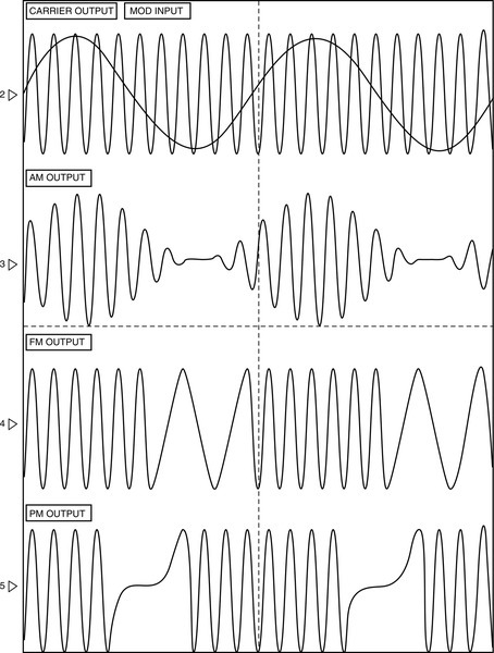
Analog RF systems modulate the amplitude of the carrier frequency (AM radio); they can also modulate the frequency (FM radio) or the phase (phase modulation). Other modulation techniques include single sideband modulation, vestigial sideband modulation, and sigma-delta modulation.
Digital RF systems use a number of distinct signals to represent the data. The signal can use PSK (phase-shift keying), FSK (frequency-shift keying), or ASK (amplitude-shift keying). Amplitude-shift keying is similar to pulse code modulation (PCM), which is a digital representation of an analog signal. PCM is widely used in digital telephony and digital audio, including MP3 and other standards.
Antennas
An antenna is an arrangement of one or more electrical conductors that are designed to radiate an electromagnetic field in response to the application of an electromotive force from a fluctuating electrical current.
Antennas are to radios like tires are to cars. It is where the rubber meets the road. If the antenna is well matched to the RF signal and the environment, a good signal is emitted or received. If the match is poor, poor results are to be expected. Most RF problems are antenna problems.
Antennas are designed to operate (resonate) at a given optimum frequency, depending on the electrical length of the antenna. This is typically the length of the wire multiplied by the ratio of the speed of wave propagation in the wire. Other attributes of the antenna can be varied by its design. These include radiation pattern and impedance (dynamic resistance to the electrical current). Antennas can be configured to propagate their signals either horizontally or vertically. The signal is best received from a similar antenna operating in the same plane.
Patterns
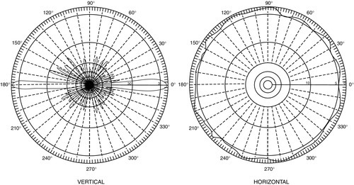
Omni Antennas
A basic antenna radiates in a circular pattern around the conductor (the antenna). This is called an omnidirectional (or omni) antenna pattern. This antenna transmits equally in all directions, either horizontally or vertically, based on the physical orientation of the antenna (Fig. 12.2).
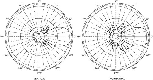
The omni antenna could be made to focus its transmission or receiving pattern more in one direction than in others by changing its physical configuration. This is accomplished at the expense of its transmission or reception ability in other directions. Of course, after doing so, it is no longer an omni antenna. Typically, a directional antenna will have a longer front lobe and weaker rear and side lobes in its pattern (Fig. 12.3).
Antenna Gain
Antenna gain is the ability of the antenna to radiate more or less in any direction compared to a theoretical antenna. If an antenna could be made as a perfect sphere, it would radiate equally in all directions. Such an antenna is theoretically called an isotropic antenna and does not in fact exist. However, its mathematical model is used as a standard of comparison for the gain of a real antenna.
Omni antennas typically radiate with a gain of 2.1 dB over an isotropic antenna. For a vertically oriented omni antenna, this gain in transmission horizontal distance from the antenna is at the expense of transmission above and below it. Its pattern looks similar to a donut.
Directional antennas can be configured with gains up to more than 20 dB. These carve a significant part out of the omnidirectional pattern of an omni antenna and can significantly extend its projection distance. A disadvantage of extreme gain antennas is that they can be very sensitive to improper position displacement due to wind conditions. There are a variety of configurations that can result in good directional RF signal transmission, including Yagi antennas, dish antennas, Luneberg lenses, and phased arrays.
Bandwidth
Each antenna is cut to resonate at a particular frequency. The bandwidth of an antenna is the measurement of its ability to operate above and below its resonant frequency.
Impedance and Coupling
Each antenna is designed to match the electromotive force of the current being applied to it. Every antenna will reflect some of that power back into the transmitter, forming a standing wave in the feed line. That power is effectively lost to RF energy and goes back into the transmitter, where it generates unwanted heat.
The amount of power reflection is measured by its standing wave ratio (SWR), which is a ratio of maximum power to minimum power in the transmission line. Too much SWR and the transmitter can burn up. As SWR increases, power out of the antenna decreases.
A SWR of 1:1 is ideal. A SWR of 1.5:1 is very good, especially for low-power applications in which the SWR consumes available transmitter power. Generally, the lower the SWR, the better.
SWR can be reduced by matching the total impedance of both the antenna and the transmission line to the output impedance of the transmitter. Every physical component in the line has an effect on impedance, including the connectors, the transmission line, and the antenna. The age of connectors and the quality of connection can cause impedance to change over time and in different environments, such as in icing conditions. The components should be closely matched to minimize antenna SWR.
Interference
Many things can interfere with good RF transmission, including automotive ignition noise, other transmitters operating in the same range, fluorescent lamps, microwave ovens and microwave intrusion alarm detectors, reflections from or blockages by large structures, and weather.
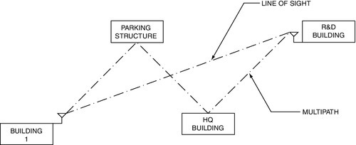
Multipath
Antennas are made to transmit across clear air and with no reflections. This is called a line-of-sight (LOS) signal. When an RF signal reflects off a large structure or body of water, that signal may also arrive at the receiving antenna. When it does, it will arrive later than the LOS signal and often out of phase from the original signal. These two signals will both be “read” by the receiver, which will try to make some sense of what it is seeing. Often, the reflected signal will interfere with the LOS signal, sometimes even to the extent that the receiver can no longer effectively act as a receiver.
Dr. Jack Nilson designed and patented a unique multi-polarized omnidirectional antenna that is especially designed to reduce the effect of interferences and multipath signals in the 802.11 ranges. With its radome removed, the antenna looks like a large spider, on its back writhing in agony. These antenna “legs” are angled precisely to gather the signals that are late and out of phase, and the antenna recombines them at its base into a single in-phase and real-time signal. The result effectively is gain produced from interference.
To optimize RF transmissions, it is advisable to encourage a good RF performance and interference study in the real-world environment.
How RF Systems Differ from Cabled Systems
Circuiting
Although designers do not often think of RF systems as having “circuits,” it is easier to imagine how they work.
• Point to point: The most basic type of transmission, a point-to-point RF circuit, involves a single transmitter/receiver pair transmitting only to each other.
• Point to multipoint: In a point-to-multipoint circuit, a number of transmitters or transceivers point to a single antenna.
• Wireless mesh: A wireless mesh system is one in which the radios can communicate with any number of nearby radios. Wireless mesh systems are usually more reliable, robust, and redundant than point-to-multipoint systems.
• Cascading design: Wireless mesh systems can also be configured to retransmit the signal of a single camera down a line of other wireless mesh nodes like a daisy chain or string of pearls, sending the first signal a long distance and combining it with the signals of other cameras along the way. This is a specialized application that requires very high expertise to design properly.
Weather Factors
Weather has an important effect on the effectiveness of wireless communications. The effects of weather should be taken into consideration in any RF design.
Transmission Physics
RF systems are fraught with problems for the uninitiated. Virtually all of them are solvable. One just has to know how to solve them. The major obstacle is not knowing what you do not know. The following sections discuss RF problems and how to prevent them. Where they cannot be prevented, I will talk about how to solve them.
Transmitter Power
RF security systems are typically transmitting digital data and may transmit a mix of video, alarm/access control data, and voice. The first issue is one of transmitter power. As for most RF problems, the system works best in a “Goldilocks and the Three Bears” comfort zone. That is, not too much power, not too little power, but enough to be “just right.” Just right differs from one system to the next, so check the system specifications.
There are two factors at play to achieve this goal: distance and transmitter gain. For distance, the inverse square law applies. That is, for each doubling of distance from transmitter to receiver, you will see one-fourth of the power. So the energy twice as far from the source is spread over four times the area (therefore, at any point at that distance there is one-fourth the power). At three times the distance, it is spread over nine times the area (one-ninth the power), at four times the distance it is spread over 16 times the area (1/16th the power), and so on.
There is a maximum distance beyond which a given transmitter and antenna will not have enough power to be received by their corresponding receiver and antenna. Likewise, there is a distance below which there is simply too much power for the system to work.
Therefore, it is important to know the acceptable minimum and maximum power at a receiver and then adjust the transmitter power and antenna gain to accommodate that figure. In most cases with better RF data equipment, it is possible to adjust the transmitter gain to accommodate the required receiver signal strength of the closest and farthest wireless nodes to which each transmitter is intending to send data. Transmitter power is usually adjustable in 3-db (half-power) increments, and antenna gain is also rated in decibels.
Antenna Loss/Gain
Transmitter power is rated based on a 0-db antenna load—that is, the resistance and output of the antenna are assumed to be exactly the same as those of the transmitter feeding it. A dipole antenna (simple rubber duck-type antenna) is often configured as a 0-db antenna.
Antennas are also available with either gain or loss. Antennas with gain perform better than a 0-db antenna, and antennas with loss perform less well (not always a bad thing).
Antenna gain and loss are factors of physics. A 0-db antenna inherently transmits an omnidirectional pattern (perfect circle horizontally). To visualize the pattern, imagine a donut. The hole in the center is where the antenna is placed, vertically oriented. The donut pattern would be the pattern of transmission from the antenna. To achieve gain, one must understand the principle of balloons. When inflated, balloons have a finite volume and a finite surface area. If a balloon is round, like the donut, one can make one side larger by pushing in on the other side. More here equals less there. Antenna patterns are similar. To get gain in one part of the antenna pattern, one must create losses in another. Directional antennas achieve gain by their directionality. That is, they have farther reach in one direction (gain) by sacrificing reach in other directions.
Antenna Patterns
The following are common antenna patterns:
• Cardiod—heart-shaped
• Yagi array—long node on one side and little radiation elsewhere
Transmission Losses
Transmission losses result in lower signals than the math would indicate. These typically result from any of the following conditions:
• An obstruction in the path of the transmitter–receiver field
• A reflecting surface (see Multipath)
• Poor connections to the transmitter, transmission line, or antenna
• Poor ground for the transmitter or antenna
• Adverse environmental conditions (fog, rain, humidity, etc.)
• Transmitting cable losses (which can be significant)
Of all the conditions that can cause problems, environmental effects are the most difficult to calculate (some say virtually impossible). This is one of the most important reasons to design the system with adequate headroom in the circuit to accommodate unpredicted losses. I recommend that any data system should not be taxed above 45% of its rated headroom. That is, if the system is designed to accommodate 100 Mbps, do not send more than 45 Mbps across it. For 54 Mbps, send no more than 24 Mbps.
Line of Sight
Line-of-sight (LOS) transmissions are the basic form of RF transmission. In a LOS transmission, there is a transmitter, receiver, and free air in between with no obstructions or reflecting objects such as buildings. LOS transmissions are the ideal. This rarely occurs.
Fresnel Zone
If a transmitter and receiver are located on two buildings some distance apart, their communication path is not defined by a single thin line of RF energy between the points. Rather, its pattern looks something like a cartoon cigar (thin on the ends and thick in the middle). The Fresnel (pronounced fra-nel) zone is the area around that thin line between the transmitting and receiving antennae (Fig. 12.4).
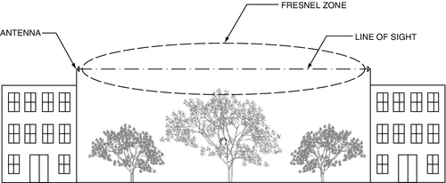
Certain RF signals (especially 2.4-GHz waves) are absorbed by water, such as the water in trees. Thus, if trees lie within the imaginary cigar around the line of sight, then the received power may be less during wet periods than during dry periods and will certainly be less than if the trees were not there at all.
Additionally, any buildings, oil tanks, ships, bodies of water, or other featueres that lie within the Fresnel zone can also create multipath reflections, including the potential for gains, losses, and secondary data images.
Multipath
What is multipath? Multipath is the effect on RF signals of reflected signals. Whenever an RF signal is transmitted, there exists the opportunity for secondary (undesired) reflections of the signal reaching the receiving antenna, not just the intended (LOS) signal (Fig. 12.5).
Multipath can most easily be understood by considering an old analog television signal received off the air. If you tune through the channels, you will likely find a channel on which you can see a good image, but you may also see a ghost image just to the right, perhaps 1 in. to the right of the sharp image. That secondary image is multipath. It is caused by the television signal being reflected off a large building or other distant object. The primary signal is the sharp image you see, and the multipath signal is the softer one, displaced to the right of the primary image.
Delay Losses
The multipath signal is shifted to the right because the reflected image takes longer to travel to the receiving antenna than the primary signal. That greater distance causes the secondary (multipath) signal to be delayed by a factor of the greater distance and the wavelength of the frequency of the channel on which it is operating. Accordingly, because it arrives at the receiving antenna later, it gets processed later. On an analog television signal, it will be displayed to the right of the primary signal by the amount of time between the arrival of the primary and secondary signals.
The results of multipath delays on digital signals display as dropped packets. This is because for every primary packet, there is a duplicate secondary packet that is being received by the receiver. So for each reflection, there is a doubling of the number of packets being sent. More reflections, more packets by a multiple of the number being reflected. On strong multipath environments, this can swamp the front end of the receiver, causing it to fail because it cannot process all these extra packets. The result is dropped packets.
For video images, the result can be seen as splotchy images because the receiver cannot keep up with the primary signal stream, and it ends up mixing secondary packets in with the primary packets as it attempts to reassemble the packet sequence of the image.
For audio, it results in lost packets, which sound like dropped syllables or just extraneous noise. You can hear these commonly on hand phones in bad areas.
For data systems, the result is lost connections or no loss at all. Data systems use the TCP/IP protocol, which goes back to get a replacement for any lost packets and does not present the information until the entire data group is reassembled. When it cannot, it simply drops the connection.
Cancellation Losses
Because multipath signals arrive not only later but also often out of phase (not oriented the same as the transmitting antenna— pure vertical or pure horizontal), some signal cancellations can occur. Additionally, the simple fact of the delay can cause signals to arrive out of phase. Out-of-phase signals can effectively reduce the quality when they combine with a good signal at the receiving antenna. This has the effect of creating artificial distance for the good signal, reducing its effectiveness and sometimes making the multipath signal the only one seen by the receiving antenna. Multipath is a major problem and should be eliminated where possible by careful positioning of the antennae.
When it is not possible to eliminate multipath, a special antenna exists that seems to effectively minimize multipath signals. Underneath its radome, this antenna looks like a spider that has died in agony, lying on its back. The spider legs are twisted into many different angles, forming curves, all carefully calculated to either accept or recombine multipath signals or to cancel them out. The antenna effectively gets gain from multipath while nearly eliminating its bad effects.
Cascade Losses
As wireless digital signals are propagated through a sequence of nodes, cascade losses occur. These are discussed in the section on full-duplex wireless mesh networks. Antenna patterns must also be observed.
Power Stability and Reliability
Stable system operation depends on stable alternating current power. In most of the developed world, stable power is taken for granted. However, that is not always the case. Increasingly, even in the developed world, power instability is becoming a problem as increasing demands create brownouts and rolling blackouts. Stable power must be ensured, especially for mission critical systems, such as for nuclear power plants, central banks, museums, hospitals, and research and development facilities.
In order to ensure stable power, the designer should check the history of power stability in the area. If power is suspect, arrangements should be made for emergency power. This might include an emergency generator and an uninterruptible power supply. Both should be sized to accommodate the expected load plus 50%, with a lower limit of 25%.
Grounding and Powering
After reliable power, grounding is the second most important aspect regarding system power. The two chief issues regarding grounding are ground stability and ground loops.
System grounds can cause reliability problems for any data system. In an analog audio system, a poor ground can easily be heard as a persistent 50- or 60-cycle hum (depending on whether a facility is in a 50- or 60-Hz power grid). Although one cannot hear the persistent hum of a poor ground in a data system, its effects are equally as evident in poor system performance.
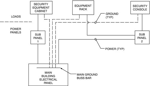
I recommend a so-called hospital ground (IEEE 602-1996 and NFPA 99-1996) as a cure-all for system grounds. A hospital ground depends on a single ground point tied to the copper ground bar of the main electrical feed of the building. All system grounds to all assemblies should emanate from this one location (Fig. 12.6). Power receptacles, power strips in assemblies, racks, and consoles all should ground to this one point. This alone ensures a reliable ground.
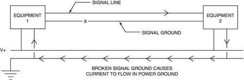
Ground loops can also create many system reliability problems. A ground loop is created when two devices are powered and grounded from separate locations and there is a voltage difference between the ground points. Because the system is attempting to reference ground from two different voltage potentials, it may not be able to pass data between the signal connections of two different parts of the system because they no longer have a single point of reference (Fig. 12.7). To eliminate this problem, system components in different buildings, or those fed from different main electrical panels, should be electrically isolated by fiber optics or RF connections. There should be no exceptions to this rule because ground faults can be fatal, especially between buildings.
The security designer should intimately know the source of electrical power for his or her systems. Never assume that the power is acceptable or that all is well. As former U.S. President Ronald Reagan once said: “Trust but verify.”
System Resets and Restores
The security designer should also ask, What happens if power to any component of the system is interrupted? Will the system reset itself or will manual intervention be required? The answer to that, of course, is that manual intervention should never be required. The system should be designed such that in the event of a cold reset of any part of the system, it will restore quickly to its appropriate operating configuration, fully automatically. Surprisingly, a number of major systems fail this test. It pays to know.
Special Power Problems
The secret to successful design is to always understand the environment in which one is operating. This is especially true of extreme environments. Extremes of cold, heat, and power can often be encountered.
One example is that of unmanned offshore oil platforms or oil pipeline lift stations. In both cases, there is no utility company power available; power is typically available only from an uninterruptible power supply that is refreshed by solar panels. For such environments, power usage calculations are essential, as is a design philosophy tilting toward using little or no power. Sometimes these conditions require one to totally rethink one’s approach to systems design. One method is to eliminate as much standard equipment as possible. Instead of wiring conventional or digital cameras to a digital video recorder, one can use digital cameras that have a built-in processor and memory in lieu of a recorder. Also, instead of using a conventional digital switch, the SCADA PLC or similar equipment already on the platform or lift station can often be used as a digital switch. Finally, there is no need to power the cameras except when actually viewing one. Cameras can be turned on automatically in response to alarms, and alarms can be managed by the SCADA system instead of a conventional alarm panel. All this eliminates unnecessary power consumption.
Each unique environment may present its own challenges. Thinking outside the box, one can often find unique and workable solutions.
Summary
RF systems can be either analog or digital. Wireless systems operate on many frequencies. Antenna patterns include omnidirectional and directional. Directionality is achieved in one direction at the expense of all other directions. Reducing an antenna’s reach in one direction achieves gain in another. Antennas transmit along a LOS to each other. The designer should observe the Fresnel zone around the LOS transmission, within which interference can occur. Interference includes RF (ignition noise or other radios), multipath, and obstructions (trees, etc.) as well as weather. RF architecture includes point to point, point to multipoint, and wireless mesh. Protocols include unicast and multicast, TCP, UDP, and RTP. The design must be adjusted to accommodate multipath and delay losses.
Stable power is the basis for a high-quality security system. Grounding is the source for many system problems. A hospital ground is the most reliable grounding method. Special power problems can be solved by thoroughly understanding the environment.
Questions and Answers
1. Radio frequency (RF) system are:
a. Always as reliable as wired systems
b. Never as reliable as wired systems
c. Usually as reliable as wired systems
d. None of the above
2. All RF systems have several basic elements, including:
a. A signal source, power injector, transmitter
b. Receiver or transceiver
c. Transmission line and antenna
d. All of the above
3. Antennas are to radios:
b. Like tires are to cars
c. Like bicycles are to fish
d. None of the above
4. The omni antenna could be made to focus its transmission or receiving pattern:
a. Less in one direction and more in several other directions
b. Toward the source
c. More in one direction than in others by changing its physical configuration
d. None of the above
5. A disadvantage of extreme gain antennas is that they can be:
a. Very sensitive to interference by nearby conversations
b. Very sensitive to improper weather conditions
c. Very sensitive to improper position displacement due to wind conditions
d. None of the above
6. A Standing Wave Ratio (SWR) of:
b. 2:1 is ideal.
c. 3:1 is ideal.
d. 4:1 is ideal.
7. Multipath is:
a. The effect on RF signals of reflected signals
b. The effect of reflected signals off glass
c. The effect of reflected signals off metal structures
d. None of the above
8. Because multipath signals arrive not only later but also often out of phase (not oriented the same as the transmitting antenna— pure vertical or pure horizontal):
a. The reflected signal can be stronger than the original signal.
b. The reflected signal can be inverted from the original signal.
c. Some signal cancellations can occur.
d. All of the above are true.
9. The two chief issues regarding grounding are:
a. Ground stability and ground stakes
b. Ground stability and ground loops
c. Ground loops and ground stakes
d. None of the above
10. The system should be designed such that in the event of a cold reset of any part of the system,
b. It will restore quickly under manual control.
c. It will restore quickly with a minimum of operator intervention.
d. It will restore quickly to its appropriate operating configuration, fully automatically.
Answers: 1: b, 2: d, 3: b, 4: c, 5: c: 6: a, 7: a, 8: c, 9: b, 10: d