Overview of Routers and Routing
Routers are devices that direct traffic between hosts. They build routing tables that contain collected information on all the best paths to all the destinations that they know how to reach. The steps for basic routing are as follows:
|
1.
|
Routers run programs referred to as routing protocols to both transmit and receive route information to and from other routers in the network.
|
|
2.
|
Routers use this information to populate routing tables that are associated with each particular routing protocol.
|
|
3.
|
Routers scan the routing tables from the different routing protocols (if more than one routing protocol is running) and select the best path(s) to each destination.
|
|
4.
|
Routers associate with that destination the next-hop device's attached data link layer address and the local outgoing interface to be used when forwarding packets to the destination. Note that the next-hop device could be another router, or perhaps even the destination host.
|
|
5.
|
The next-hop device's forwarding information (data link layer address plus outgoing interface) is placed in the router's forwarding table.
|
|
6.
|
When a router receives a packet, the router examines the packet's header to determine the destination address.
|
|
7.
|
The router consults the forwarding table to obtain the outgoing interface and next-hop address to reach the destination.
|
|
8.
|
The router performs any additional functions required (such as IP TTL decrement or manipulating IP TOS settings) and then forwards the packet on to the appropriate device.
|
|
9.
|
This continues until the destination host is reached. This behavior reflects the hop-by-hop routing paradigm that's generally used in packet-switching networks.
|
EGPs, such as BGP, were introduced because IGPs do not scale well in networks that go beyond the enterprise level, with thousands of nodes and hundreds of thousands of routes. IGPs were never intended to be used for this purpose. This chapter touches on basic IGP functionality.
Basic Routing Example
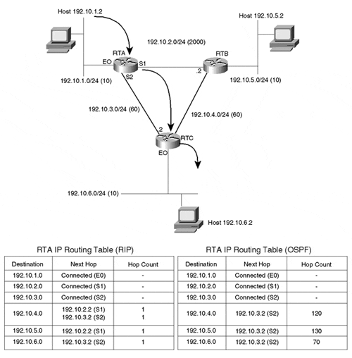
Figure 4-1 describes three routers—RTA, RTB, and RTC—connecting three local area networks—192.10.1.0, 192.10.5.0, and 192.10.6.0—via serial links. Each serial link is represented by its own network number, which results in three additional networks, 192.10.2.0, 192.10.3.0, and 192.10.4.0. Each network has a metric associated with it, indicating the level of overhead (cost) of transmitting traffic on that particular link. The link between RTA and RTB, for example, has a cost of 2,000, much higher than the cost of 60 of the link between RTA and RTC. In practice, the link between RTA and RTB might be a 56 Kbps link with much larger delays than the T1 link between RTA and RTC and the T1 link between RTC and RTB combined.
Figure 4-1. Basic Routing Behavior

Routers RTA, RTB, and RTC would exchange network information via some IGP and build their respective IP routing tables. Figure 4-1 shows examples of RTA's IP routing table for two different scenarios; the routers are exchanging routing information via RIP in one scenario and OSPF in another.
As an example of how traffic is passed between end stations, if host 192.10.1.2 were trying to reach host 192.10.6.2, it would use its local manually installed default route to first send the traffic to RTA. RTA would look in its IP routing table for any network that matches this destination and would find that network 192.10.6.0 is reachable via next-hop 192.10.3.2 (RTC) on serial line 2 (S2). RTC would receive the traffic and would try to look for the destination in its IP routing table (not shown). RTC would discover that the host is directly connected to its Ethernet 0 interface (E0) and would send the traffic to 192.10.6.2.
In this example, the routing is the same whether RTA is using the RIP or OSPF scenario. RIP and OSPF, however, fall into different categories of IGP protocols—distance vector protocols and link-state protocols, respectively. For a different routing example in Figure 4-1, the results might be different depending on whether you are looking at the RIP or OSPF scenario. It is useful at this point to consider characteristics of both IGP protocol categories to see how protocols generally have evolved to meet increasingly sophisticated routing demands.
