
Chapter 12. Working with Tables
Chapter Objectives
• Creating tables from scratch by entering the data manually
• Creating tables by linking with a Microsoft Excel spreadsheet
• Managing data links using the Data Link Manager
• Controlling the appearance of tables using table styles
• Modifying tables using grips
• Inserting formulas in a table
Introduction
A table is an AutoCAD annotation object type that consists of data in rows and columns similar to an accounting spreadsheet. Many of the common spreadsheet features you may be familiar with work exactly the same in AutoCAD tables. It is even possible to paste a Microsoft Excel spreadsheet so that it converts directly into a static AutoCAD table with the desired formatting and fonts. Even better, you can link a dynamic AutoCAD table directly to an external Excel spreadsheet so that it updates automatically if the spreadsheet changes. Figure 12-1 shows an example of a table being used for an Architectural window schedule.
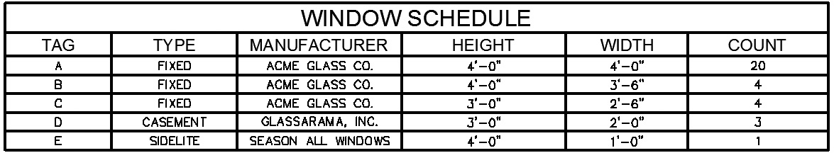
Figure 12-1Table used for an Architectural window schedule
You can create a table based on three different types of data:
• Static data Manually enter data into a table created from scratch or from pasting Excel data using the Windows Clipboard
• Externally linked data Create a dynamic AutoCAD table by linking to an existing Excel spreadsheet
• Object data Create an AutoCAD table from object data in the drawing using the Data Extraction wizard, which allows you to extract different object properties, including blocks and block attributes
Using table styles, you can control all aspects of a table including the cell data format, the text and border properties, table direction, and other formatting options.
cell: The box at the intersection of a table row and column that contains the table data or a formula. A cell is typically referenced using its column letter and row number separated with a colon. For example, the cell in column A and row 1 is referenced as A:1.
After the table has been created, the complete table, or individual rows and columns, can be resized using grips. Additional modifications can be made using the right-click shortcut menus or the Table Cell context tab of the ribbon explained later in the section on modifying tables.
Creating Tables from Scratch
The TABLE command creates a table object by inserting an empty table in the drawing at a specified point or defined window area using the table style, number of rows, columns, and sizes you specify.
|
TABLE |
|
| Ribbon & Panel: | Home | Annotation |
| Menu: | Draw | Table… |
| Command Line: | TABLE |
| Command Alias: | TB |
When you start the TABLE command, AutoCAD displays the Insert Table dialog box shown in Figure 12-2.
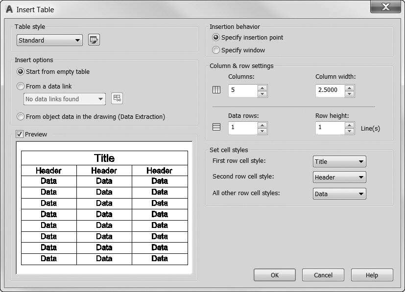
Figure 12-2The Insert Table dialog box
The Table style area at the top left side of the dialog box is used to control the appearance of the table.
The drop-down list allows you to select an existing table style and make it current. The default style is Standard. Selecting the button to the right displays the Table Style dialog box so that you can update the current style or add a new table style. Table styles are discussed later in this chapter.
Below the Table style area is the Insert options area where you select one of the three ways to insert a table. The default method is Start from empty table. If you select any of the other table insert options, most of the other options on the right will be disabled.
The table Preview provides an example of what the current table style looks like.
The Insertion behavior section allows you to select how you want to locate the table. You can use an insertion point or specify a window boundary area.
The Specify insertion point option allows you to specify the location of the upper left corner of the table.
The Specify window option allows you to locate and size the table by defining a rectangular window area. The specified column width and the final number of rows depend on the size of the boundary area.
The table is sized using the number and size of the rows and columns specified in the Column & row settings area on the right side of the dialog box.
The Columns: box is used to specify the number of columns.
The Column width: box is used to specify the width of the columns.
The Data rows: box is used to specify the number of rows. A table style with a title row and a header row has a minimum of three rows.
The Row height: box is used to specify the row height in lines. The height of a line is based on the current text height and the cell margin settings in the current table style. Table styles are explored later in this section. The minimum row height is one line.
It is possible to create and apply different cell styles per row so that you can create different formatting for titles, headers, and data, if desired. The Set cell styles area allows you to assign the different styles independent of the current table style.
The First row cell style list box controls the cell style for the first row in the table. The Title cell style is used by default.
The Second row cell style list box controls the cell style for the second row in the table. The Header cell style is used by default.
The All other row cell styles list box controls the cell style for all other rows in the table. The Data cell style is used by default.
Selecting OK closes the dialog box, and AutoCAD prompts you to Specify insertion point: so you can locate the table. After the table is inserted, you are placed in Edit mode. The Text Editor context tab of the ribbon explained in Chapter 11 is displayed, and your cursor is in the first data cell ready for data entry. Adding and modifying table data are explained in the following section.
Entering Table Data
When a table is inserted, you are placed in Edit mode so that the Text Editor context tab of the ribbon is displayed and the first data cell is highlighted so that you can begin entering data. To move to an adjacent cell in the same row, you can use the left and right arrow keys or press the <Tab> key to go to the cell on the right. To move to an adjacent cell in the same column, you can use the up and down arrow keys or press <Enter> to go to the cell directly below in the next row.
You can use any of the text formatting features and options explained earlier in the “Creating Multiline Text” section in Chapter 11 to format the text in each cell. When you are editing text, the arrow keys move the text cursor and do not take you to another cell.
When you are finished adding data to the table, you can use the same methods used for multiline text to close out of Edit mode and accept any additions and changes:
• Select Close Text Editor in the Close panel of the Text Editor context tab of the ribbon.
• Click anywhere outside the text editor with your mouse.
• Hold down the <Ctrl> key and press <Enter>.
Creating Tables by Inserting a Data Link
The second way to insert a table is to link it to an existing Microsoft Excel spreadsheet using the From a data link method in the Insert options area of the Insert Table dialog box shown in Figure 12-2. Using data links, you can display tabular data from a spreadsheet as an AutoCAD table. This allows you to take advantage of AutoCAD fonts, colors, text styles, and all of the other table formatting options while still maintaining a link to the original Excel data. If the Excel spreadsheet is updated, a notification balloon like the one shown in Figure 12-3 is displayed in the status tray on the right side of the status bar. It contains a link that lets you quickly update the table in the drawing so that it matches the Excel spreadsheet.
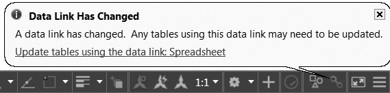
Figure 12-3The Data Link Notification balloon
The Data Link Manager
When a new data link is created, you must give it a name, usually related to the type of data, and select the external file to which it links (XLS or CSV) using the Data Link Manager shown in Figure 12-4.
|
DATA LINK MANAGER |
|
| Ribbon & Panel: | Insert | Linking & Extraction |
| Menu: | Tools | Data Links | Data Link Manager… |
| Command | DATALINK |
| Command Alias: | DL |
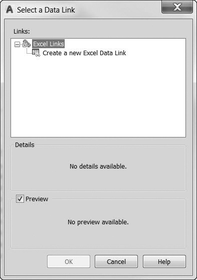
Figure 12-4The Select a Data Link dialog box
After entering a name and choosing a file, AutoCAD displays the New Excel Data Link dialog box shown in Figure 12-5. There you can choose which sheet in the file you want to link and whether you want to link to the entire sheet or just a specific range of cells.
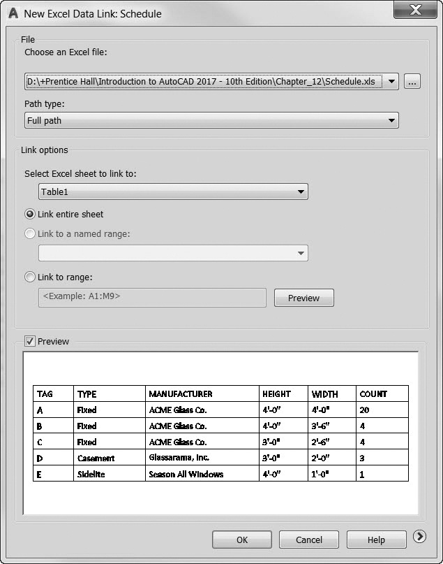
Figure 12-5The New Excel Data Link dialog box
Once the link has been established, select OK to close the Data Link Manager and return to the Insert Table dialog box. A preview of the linked table is shown at the bottom of the dialog box.
Selecting OK closes the dialog box, and AutoCAD prompts you to Specify insertion point: so you can locate the table. The table is inserted without putting you in Edit mode because the data are already created. It is possible to modify the table after it is inserted using the methods explained in the next section. Be careful, though, because changes made in the table do not automatically update the linked Excel spreadsheet.
|
TABLE STYLE |
|
| Ribbon & Panel: | Home | Annotation |
| Menu: | Format | TableStyle… |
| Command Line: | TABLESTYLE |
| Command Alias: | TS |
Managing Table Styles
Table styles are used to control the appearance of tables by allowing you to:
• Set the cell text style, height, data type, and alignment
• Control the cell border properties so you can set the border line thickness and color and turn border lines on and off
• Set the table text flow direction from top to bottom or bottom to top
• Set the horizontal and vertical cell margin distance
The TABLESTYLE command allows you to modify an existing table style or create a new one.
When you start the TABLESTYLE command, AutoCAD displays the Table Style dialog box shown in Figure 12-6.
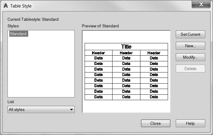
Figure 12-6The Table Style dialog box
To create a new table style, select the New… button and enter the new table style name in the Create New Table Style dialog box. You can select an existing table style as a starting point by selecting it from the Start With: list. Selecting the Continue… button displays the New Table Style dialog box shown in Figure 12-7.
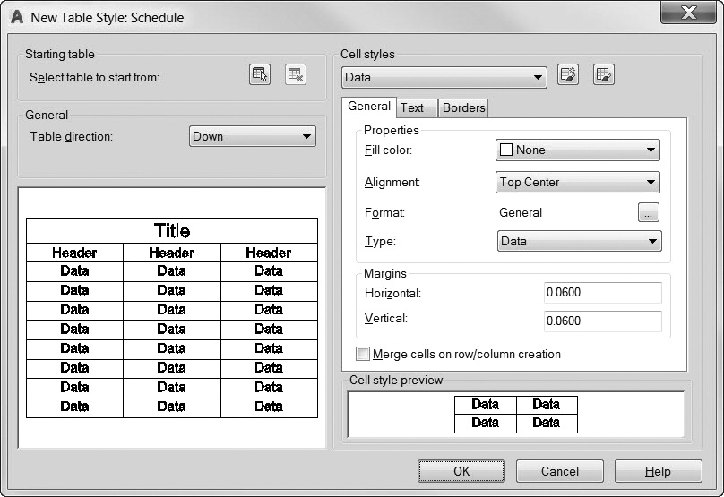
Figure 12-7The New Table Style dialog box
The options in the Modify Table Style dialog box displayed when you select the Modify… button on the Table Style dialog box are exactly the same as those in the New Table Style dialog box.
You can select a table in your drawing to use as a starting point for the new table style in the Starting table area at the top left of the dialog box.
The Table direction: list box controls the direction of the text flow for the table.
• Down Text reads from top to bottom (Default)
• Up Text reads from bottom to top. The title row and column heads row are located at the bottom of the table
On the right side of the dialog box, there are three tabs that control the properties for the three default cell types in the Cell styles list box at the top:
• Data
• Header
• Title
You can set up and apply these different cell types to any row when you insert a table. You can also create your own cell styles via the Manage Cell Styles dialog box accessible by selecting the button to the right of the Cell styles list box.
The General tab controls general formatting and data type settings:
• The Fill color: list box controls the background color of the cell. The Select color… list item displays the AutoCAD Select Color dialog box.
• The Alignment: list box controls justification and alignment for text in a cell. The same justification options are available as used for multiline text explained earlier in Chapter 11.
• The Format: setting controls the data type and display for the text in the cell. Selecting the … button to the right of the current Format: setting displays the Table Cell Format dialog box shown in Figure 12-8.
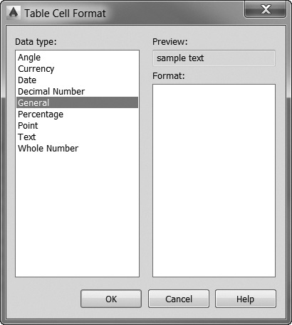
Figure 12-8The Table Cell Format dialog box
• The Margins area is used to control the spacing, or margin, between the cell border and the cell content. The default margin setting is 0.06–.
• The Horizontal: text box sets the distance between the cell text and the left and right cell borders.
• The Vertical: text box sets the distance between the cell text and the top and bottom cell borders.
The Text tab controls different text formatting settings:
• The Text style: list box lists all of the text styles in the drawing. The … button to the right displays the Text Style dialog box so you can create a new text style.
• The Text height: box sets the text height. The default text height for data and column head cells is 0.1800. The default text height for the table title is 0.25.
• The Text color: list box controls the text color. The Select color… list item displays the AutoCAD Select Color dialog box.
The Borders tab allows you to control the lineweight, linetype, and color of all four cell borders:
• The Lineweight: list box controls the lineweight for the borders you specify by selecting a border button below.
• The Linetype: list box controls the linetype for the borders you specify by selecting a border button below.
• The Color: list box controls the color for the borders you specify by selecting a border button below. The Select color… list item displays the AutoCAD Select Color dialog box.
• Checking the Double line check box will draw a double line border using the spacing specified below.
The buttons across the bottom determine to which border lines the properties above are applied.
• The All Borders button applies the border property settings to all four cell borders.
• The Outside Border button applies the border property settings to just the outside border of all cells.
• The Inside Border button applies the border property settings to the inside border of all cells. This option does not apply to title row cells.
• The Bottom Border button applies the border property settings to the bottom borders of all cells.
• The Left Border button applies the border property settings to the left borders of all cells.
• The Top Border button applies the border property settings to the top borders of all cells.
• The Right Border button applies the border property settings to the right borders of all cells.
• The No Border button hides borders for all cells.
Exercise 12-1 Creating a Table from Scratch
![]() Start a new drawing using the acad.dwt drawing template.
Start a new drawing using the acad.dwt drawing template.
![]() Create a text style named Notes with the following settings:
Create a text style named Notes with the following settings:
a. Font = Simplex.shx AutoCAD font
b. Height = 0.125>
![]() Create a text style named Titles with the following setting:
Create a text style named Titles with the following setting:
a. Font = Arial TrueType font
![]() Create a new table style named Schedule with the following settings:
Create a new table style named Schedule with the following settings:
a. Set the Data rows text style to Notes.
b. Set the Title row text style to Titles.
c. Set the Header row text style to Titles.
d. Set the text alignment to Middle Center for all rows.
e. Set all border line lineweights to 0.50 mm for all rows.
![]() Create the window schedule shown in Figure 12-9 using the TABLE command with the Schedule table style you just created.
Create the window schedule shown in Figure 12-9 using the TABLE command with the Schedule table style you just created.
![]() Save the drawing as CH12_EXERCISE.
Save the drawing as CH12_EXERCISE.
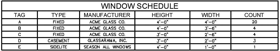
Figure 12-9Window schedule
Modifying Tables
There are two levels of modifying and editing an existing table: table level and cell level. Both methods rely on using grips.
You select a table by clicking directly on a table line so that the table level grips are displayed as shown in Figure 12-10.
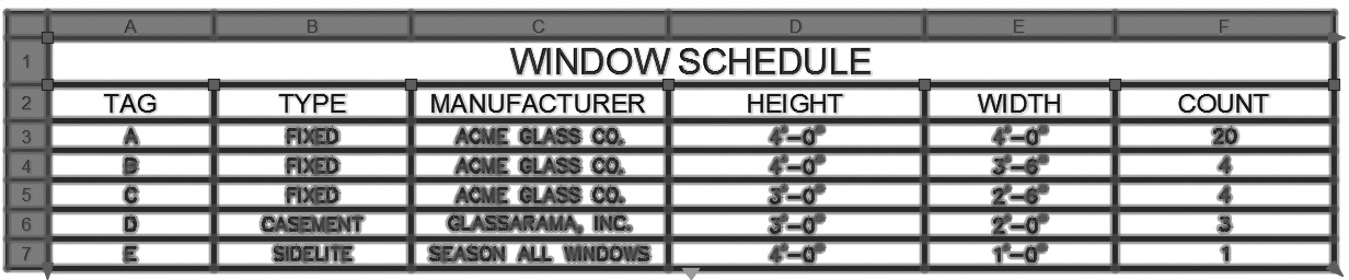
Figure 12-10Selecting a table for editing using grips
You can use the table grips to resize the table by stretching any corner except the insertion corner point. The insertion grip point moves the table. When you change the height or width of a table using grips, the rows and columns change proportionally.
You can change column widths by selecting a grip at the top of a column line and stretching it to another location. To also change the table width, press <Ctrl> while selecting the column grip.
The light blue triangle grip at the bottom center of the table is the table-breaking grip. A table with a large amount of data can be broken into primary and secondary table fragments. You can use the table-breaking grips found at the bottom of a table to make a table span multiple columns in your drawing or to manipulate the different table parts that have already been created.
The Right-Click Menu
All the other table-level editing options are provided via the right-click menu shown in Figure 12-11.
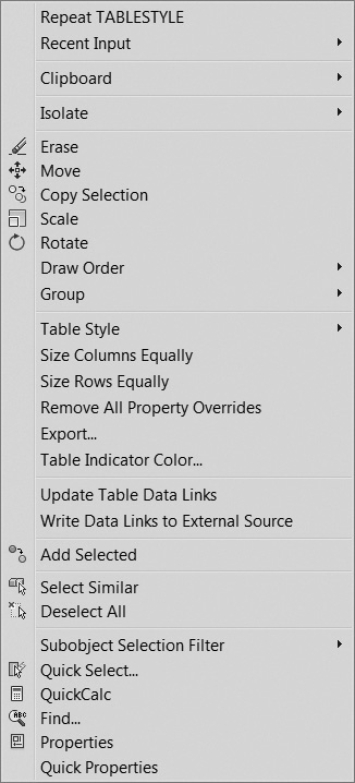
Figure 12-11The Table Editing right-click menu
The Table Style menu item displays a cascade menu with the available table styles in the current drawing so you can change styles.
The Size Columns Equally menu item resizes all columns equally.
The Size Rows Equally menu item resizes all rows equally.
The Remove All Property Overrides menu item will reset the table back to its default format.
The Export… menu item allows you to export the table to a comma-delimited file via the Export Data File dialog box.
The Table Indicator Color… menu item allows you to change the color of the row/column indicators in the table editor using the standard AutoCAD Select Color dialog box.
The Update Table Data Links menu item updates the table with any changes in linked data if applicable.
The Write Data Links to External Source menu item writes any table data changes back to any linked source files.
Modifying Table Cells
To modify a table cell, you must click inside the cell with your mouse so the four cell grips display at the midpoints of each cell border line as shown in Figure 12-12.
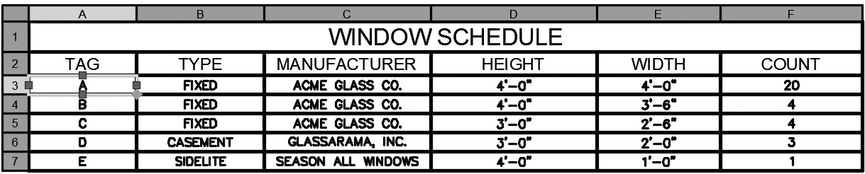
Figure 12-12Selecting a table cell for editing using grips
You can select multiple cells by clicking and dragging your cursor to create a crossing window over multiple cells. You can also select a range of cells by selecting the first cell and holding down the <Shift> key to select the last cell and all the cells in between.
The four cell grips can be used to resize a row or column by selecting the appropriate grip and dragging it to a new location.
The blue diamond in the bottom right corner can be dragged to copy and increment data automatically.
The Table Cell Context Tab of the Ribbon
When you click inside a table cell, the Table Cell context tab of the ribbon shown in Figure 12-13 is displayed.

Figure 12-13The Table Cell context tab of the ribbon
Using the Table Cell context tab of the ribbon, you can do the following:
• Edit rows and columns
• Merge and unmerge cells
• Create and edit cell styles
• Alter the appearance of cell borders
• Edit data formatting and alignment
• Lock and unlock cells from editing
• Insert blocks, fields, and formulas
• Link the table to external data
The Right-Click Menu
With a cell selected, you can also right-click and use the options on the shortcut menu shown in Figure 12-14.
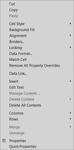
Figure 12-14The Cell Editing right-click menu
The Cell Style cascade menu allows you to change the cell style.
The Background Fill menu item allows you to specify the cell’s fill color via the AutoCAD Select Color dialog box.
The Alignment cascade menu allows you to change the cell’s text justification using one of the standard multiline text justification options.
The Borders… menu item displays the Cell Border Properties dialog box shown in Figure 12-15 so you can change the lineweight, linetype, and/or color of one or more of the cell border lines.
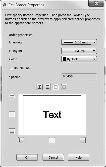
Figure 12-15The Cell Border Properties dialog box
The Locking cascade menu allows you to lock and unlock data cell content and/or data cell formatting. Tables created using data linking or data extraction are automatically locked to prevent inadvertent changes and preserve data integrity.
The Data Format… menu item displays the Table Cell Format dialog box so that you can change the data type and format for a cell.
The Match Cell menu item allows you to copy the selected cell properties to one or more additional cells.
The Remove All Property Overrides will remove all property overrides and revert back to the original table style.
The Data Link… menu item allows you to create or edit data links using the Data Link Manager.
The Insert cascade menu allows you to insert the following items into a cell:
• The Block… menu item displays the Insert a Block in a Table Cell dialog box so you can insert a block in a cell.
• The Field… menu item displays the Field dialog box so you can insert an automated text field. See the “Text Fields” section in Chapter 11 for complete information about inserting and using fields.
• The Formula cascade menu allows you to insert a formula that does calculations using values in other table cells. Inserting formulas is discussed in detail in the next section.
The Edit Text menu item displays the table editor and Text Editor context tab of the ribbon so you can edit the cell text.
The Delete All Contents menu item deletes the cell contents.
The Columns cascade menu allows you to insert a new column to the left or right of the current cell, delete columns, or size multiple columns equally.
The Rows cascade menu allows you to insert a new row above or below the current cell, delete rows, or size multiple rows equally.
The Merge cascade menu item allows you to merge two or more cells into one block, row, or column.
The Unmerge menu item turns merged cells back into individual cells.
The Properties menu item displays the Properties palette with the cell properties displayed as shown in Figure 12-16 so you can make any formatting or content changes.
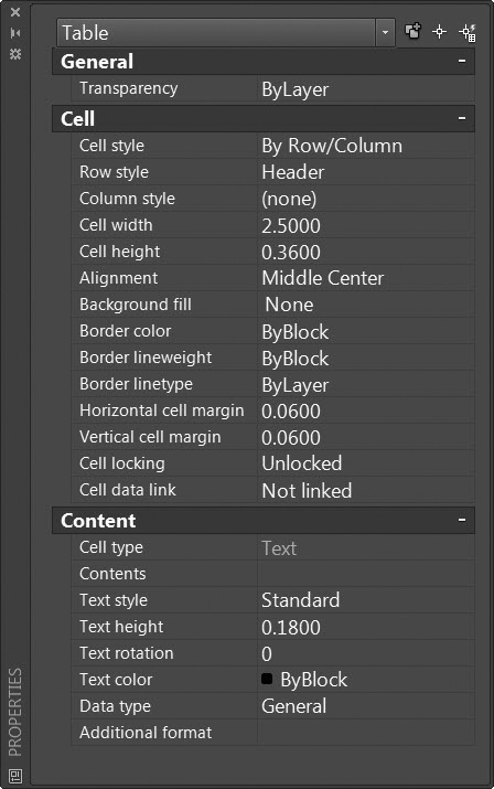
Figure 12-16The Properties palette with a table cell selected
Inserting Formulas
Table cells can contain formulas similar to an accounting spreadsheet program. AutoCAD provides the following spreadsheet type functions:
• 5Sum(A1:A10) Sums the values in the first 10 rows in column A
• 5Average(A10:E10) Calculates the average of the values in the first five columns in row 10
• 5Count(A1:D100) Displays the total number of cells in columns A through D in rows 1 through 100
• 5A11D1 Adds the values in A1 and D1
• 5A12D1 Subtracts the value in D1 from the value in A1
• 5A1*D1 Multiplies the values in A1 and D1
• 5A1/D1 Divides the value in A1 by the value in D1
• 5A1^2 Squares the value in A1. The number after ^ is the exponent
All formulas must start with an equal sign (5). Formulas perform calculations using the values in other specified table cells by referencing their column letter and row number and/or constant values. The top left cell in a table is referenced using A1. A cell range is referenced using the first and last cells separated by a colon. For example, the range A1:D10 references the cells in rows 1 through 10 and columns A through D. Merged cells use the letter and number of the top-left cell.
When you copy a formula from one cell to another, the range changes to reflect the new location. For example, if the formula in A11 sums A1 through A10, when you copy it to B11 the range changes so that the formula sums B1 through B10.
You can insert a formula via the Cell Editing right-click menu shown in Figure 12-14, select it from the Insert > Formula cascade menu on the Insert panel shown in Figure 12-17, or enter it manually using the in-place text editor.
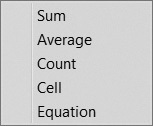
Figure 12-17The Insert Formula cascade menu
Exercise 12-2 Modifying a Table
![]() Continue from Exercise 12-1.
Continue from Exercise 12-1.
![]() Modify the window schedule as shown in Figure 12-18.
Modify the window schedule as shown in Figure 12-18.
![]() Save the drawing.
Save the drawing.
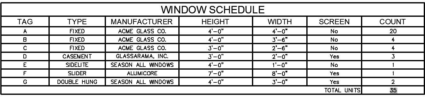
Figure 12-18Updated window schedule
Chapter Summary
Tables can be used for many different purposes ranging from parts lists to door and window schedules. Using AutoCAD tables you have the choice of creating a static table from scratch or by copying and pasting from Excel. Dynamic tables can be created that are linked to external data sources that can be updated automatically. The Data Link Manager provides the ability to maintain and manage data links in one central location.
Table styles can be created to manage different table types in a drawing so you can control text and border formatting on at least three different levels: title, header, and data rows. Using the different cell styles you can set different text heights for the title, column headers, and all of the data. Additional formatting options can be applied using right-click menu options at the table (overall) level and for each individual cell selected. Grips can be used to resize columns and even resize complete tables.
Similar to Excel, you can also insert formulas that perform calculations such as sums and averages, making it possible to create a bill of materials that has an accurate count of parts or materials or a schedule with quantity takeoffs. As you will see, even these tables themselves can be created automatically using data extraction methods explained later in Chapter 16.
Chapter Test Questions
Multiple Choice
Circle the correct answer.
1. Tables in AutoCAD are created using what type of data?
a. Object
b. Static
c. Linked
d. All of the above
2. The box at the intersection of a row and column is referred to as:
a. Field
b. Square
c. Cell
d. A:1
3. The best way to modify a table after it is inserted is by using:
a. Properties palette
b. Table Cell context tab of the ribbon
c. Grips
d. All of the above
4. A table’s appearance and formatting are typically controlled using:
a. Text styles
b. Table styles
c. Dimension styles
d. All of the above
5. The current table style can be set using:
a. Annotation panel
b. Insert Table dialog box
c. Format menu
d. a and b
6. Table cells can contain what type of data?
a. Text
b. Fields
c. Blocks
d. All of the above
7. The system variable that controls whether the in-place text editor displays column letters and row numbers is:
a. TABLECOLS
b. TABLEROWS
c. TABLEDISPLAY
d. TABLEINDICATOR
8. The Data Link Manager allows you to link to what file type?
a. XLS
b. CSV
c. MDB
d. a and b
9. The different options for starting a new table style include:
a. Copying an existing table style
b. Starting from scratch
c. Picking an existing table in the drawing
d. a and c
10. All table formulas start with:
a. Equal sign (=)
b. Parentheses
c. F
d. None of the above
Matching
Write the number of the correct answer on the line.
a. Table ______
b. Cell ______
c. Table styles ______
d. Cell style ______
f. TABLEINDICATOR ______
g. Data Link Manager ______
h. TABLEEXPORT ______
i. Table Cell ______
1. Controls individual cell characteristics that affect the appearance of cell text and borders
2. System variable that controls the display of column letters and row numbers in the table editor
3. Context tab of the ribbon used to modify tables
4. Command used to export a table to a comma-delimited file
5. Creates, edits, and manages data links
6. Command used to paste or link Excel data as an AutoCAD table
7. Controls the cell data format, the text and border properties, table direction, and other table formatting options
8. AutoCAD annotation object type that consists of data in rows and columns similar to an accounting spreadsheet
9. The box at the intersection of a table row and column that contains the table data or a formula
True or False
Circle the correct answer.
1. True or False: You can extract the lengths of all lines on a specified layer to an AutoCAD table that will update when a line changes length.
2. True or False: The best way to resize a table is by using grips.
3. True or False: It is possible to create and apply different cell styles per row so that you can create different formatting for titles, headers, and data.
4. True or False: You can create your own cell style if you want.
5. True or False: AutoCAD automatically updates an Excel spreadsheet that was pasted into your AutoCAD drawing.
6. True or False: Linked data cells are indicated by blue corner brackets.
7. True or False: The light blue triangle grip at the bottom center of a table that has grips on will copy data to adjacent cells when you drag it.
8. True or False: It is not possible to unlock and update data that are linked externally in a table.
9. True or False: All formulas must start with an open parenthesis.
10. True or False: The pound (#) symbol will create an absolute cell address.
Chapter Projects
G Project 12-1: Parts List [basic]
1. Start a new drawing using the acad.dwt template.
2. Create a table style named Parts List with the following settings:
a. Text font—Simplex.shx
b. Title row text height—0.25
c. Header row text height—0.125
d. Data row text height—0.125
e. Border lineweight 50.50 mm
3. Create the Parts List table shown in Figure 12-19 using the TABLE command.
4. Save the drawing as P12-1.
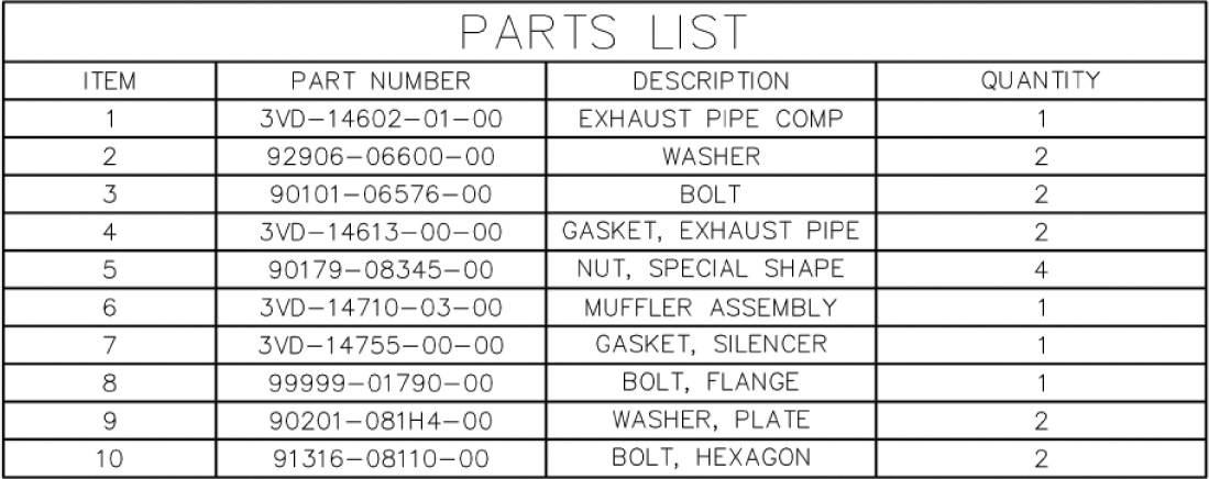
Figure 12-19
M Project 12-2: Socket Head Cap Screws, continued from Chapter 7 [intermediate]
1. Open drawing P7-2 from Chapter 7.
2. Create a table style named Screws with the following settings:
a. Text font—Romans.shx
b. Title row text height—0.25
c. Header row text height—0.125
d. Data row text height—0.125
e. Border lineweight 50.50 mm
3. Create the screw table shown in Figure 12-20 using the TABLE command.
4. Save the drawing as P12-2.
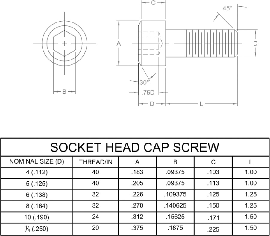
Figure 12-20
A Project 12-3: Residential Architectural Plan, continued from Chapter 11 [advanced]
1. Open drawing P11-5 from Chapter 11.
2. Create a table style named Schedule with the following settings:
a. Text font—Romans.shx
b. Title row text height—12
c. Header row text height—8
d. Data row text height—6
e. Border lineweight 5 0.50 mm
3. Re-create the window schedule created for drawing P11-5 using the TABLE command.
4. Save your drawing as P12-3.
G Project 12-4: Bill of Materials [basic]
1. Start a new drawing using the acad.dwt template.
2. Create a table style named BOM with the following settings:
a. Text font—Romans.shx
b. Title row text height—0.25
c. Header row text height—0.125
d. Data row text height—0.125
e. Border lineweight =0.50 mm
3. Create the Bill of Materials table shown in Figure 12-21 using the TABLE command.
4. Save the drawing as P12-4.
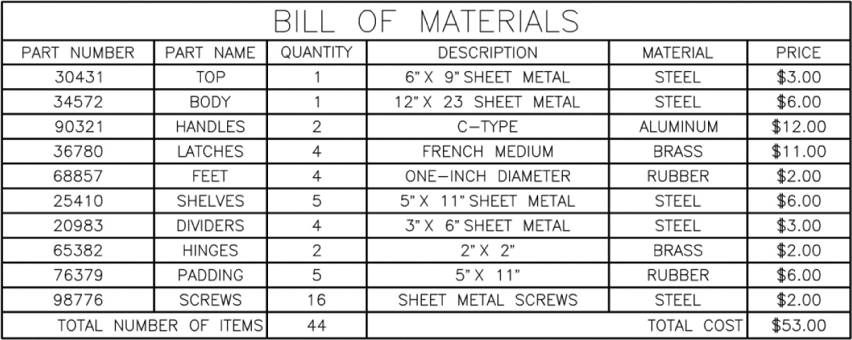
Figure 12-21
A Project 12-5: Residential Architectural Plan, continued from Project 12-3 [advanced]
2. Re-create the door schedule created for drawing P11-5 using the TABLE command using the Schedule table style.
3. Save your drawing as P12-5.