
Inspection and testing of the low-voltage (mains) supply
The Electricity at Work Regulations requires that people who conduct these tests are competent under the terms of the Health and Safety at Work Act. This chapter provides students with instruction on how these tests are safely carried out and how to achieve competence.
This chapter discusses the need to visually inspect the installation and studies the methods of testing the low-voltage supply to the system, covering earth continuity, polarity, insulation and earth loop impedance. There are certain safety precautions to be observed and procedures for recording the test results using proprietary or commercial forms need to be followed.
8.1 Visual inspection and testing
Most intruder alarm systems feature connection to the low-voltage mains supply, and the installer must therefore fully understand the requirements that apply and the safety precautions that exist.
After completion of any new wiring installation or alteration to an existing system, the work must be inspected and tested to ascertain that there are no defects and that all necessary conditions have been satisfied. However carefully an installation has been completed it is always possible for faults to occur at a later stage by nails being driven into cables, insulation being damaged and connections being broken or defective apparatus being installed.
A full test of the completion of the mains connection by the intruder alarm installer should be carried out and results carefully recorded. The local electricity board is entitled to refuse to connect a supply to a consumer if it is not satisfied that the installation complies with the relevant statutory regulations. In the UK an installation which complies with the IEE Wiring Regulations is deemed to meet the statutory requirements and should therefore qualify. The procedures for inspection and testing on completion of an installation are covered in the IEE Wiring Regulations, Part 7, which includes a checklist for visual inspection. Following the inspection, tests should be performed on the installation.
8.2 Safety precautions and test equipment
Regulations make it an offence in so far as electrical connections are concerned for a person to make permanent connection to any part of an electrical installation unless competent to do so. This is in accordance with BS 7671 and the IEE Wiring Regulations. If anyone other than a competent person installs the mains connection to any system and an accident or fire occurs as a result, then both the customer and the person that carried out the work are legally responsible. These wiring regulations have been in existence for over 100 years. They became a British Standard in 1992 and were published as BS 7671.
The intruder alarm and power supplies must be mains connected so that they comply with the Electricity at Work Regulations and the related BS 7671 standard.
The installation must also meet BS 4737 such that connection is to the mains supply via an unswitched spur unit. This must use at least 0.75 mm cable with the spur sited adjacent to the equipment. It must essentially be within arms reach of the equipment so that it can be isolated before the control panel is opened.
The fuse should be appropriate, and 3 A is typical.
BS 4737 does not specifically call for the spur to be direct from the consumer unit, but it is important to ensure that it is not possible for someone to inadvertently isolate or restore power from another source. It follows therefore that it is best to run the spur for the system direct to the consumer unit. If this is not possible, any other master spur should be marked to indicate that it also serves the security system. Drawings and diagrams should be updated to that effect.
The intruder alarm engineer should never work on any electrical apparatus that is live to the mains supply, and must power down the system before any modifications are made. Of necessity this applies when adding or changing detectors or printed circuit boards, when it is also necessary to disconnect the standby batteries and silence the sounders – beware if a non-volatile memory (NVM) is not fitted because programming will be lost so a manual would be needed!
Perhaps before we consider safety precautions we should look back a stage to how the AC mains supply is actually derived.
AC mains supply
Power supplies are generated almost everywhere as alternating current (AC), which means that the current is changing direction continually. In the UK this change of direction occurs 50 times per second (50 Hz). The machines that actually generate this power are known as generators, and they have three identical sets of windings in which the current is generated. One end of each winding is connected to a common, or star, point which is termed the neutral. The other ends of the windings are brought out to the three wires or phases of the supply cables. For identification purposes, these are colour coded as red, yellow and blue, and the currents which are transmitted in each phase have a displacement of 120°.
Power supplies to towns and villages are provided from power stations all over the country, via a system of overhead and underground mains and transformers which reduce the voltage in steps from the high transmission voltage to the normal mains voltage used by the consumer. The National Grid is responsible for the transmission of power in bulk, at 400 kV, on the Super Grid System. The local electricity boards are then responsible for the distribution of power from the grid stations to all the industrial and domestic users. This is achieved by using a network of overhead lines and underground cables (usually at 132 and 33 kV) to take the power to the main load centres, and 11 kV overhead lines and underground cables to distribute the power to individual load centres, where secondary substations reduce the voltage to mains potential. From these substations, which consist of pole-mounted transformers and isolating gear or ground-mounted transformers and switch gear, low-voltage overhead and underground mains are taken to the consumer’s supply terminals. AC power is distributed mainly on three-phase networks, although in certain rural areas only single-phase supplies are available. Thus, on the low-voltage side of most local transformers will be found four terminals: the red, yellow and blue phases and the neutral. Between each phase and the neutral there is a voltage of 240 V. However, between the phases the voltage is 415 V. For this reason the secondary output voltage of transformers is given as 415/240 V. This is illustrated at Figure 8.1.

The supply authorities are required to maintain the voltage at the consumer’s supply terminals within 6 per cent of the nominal voltage, which equates to 224–256 V. The various systems for distributing power to consumers are defined in Part 2 of the IEE Wiring Regulations, and in the UK are designated TT, TN-S or TN-C-S. Most domestic customers are provided with a single-phase supply, unless exceptionally heavy loading is expected. Most industrial premises, however are provided with a three-phase supply since the load may be high and heavy machinery requires three-phase motors.
Power transformers are more efficient if the load on each phase is approximately the same, so single-phase services are normally connected to alternate phases, and three-phase consumers are encouraged to balance their loads over the three phases.
The local boards provide underground cable or overhead line services which terminate at a convenient point within the premises. Overhead services are terminated on a bracket high up on a wall of the property, and insulated leads taken through the wall to the meter position. Underground services tend to be brought through below floor level via ducting. The overhead or underground service leads are taken into the main fuse of the electricity board. This is usually 100 A for domestic purposes. From this fuse point the supply is taken to the meter; however, when three-phase supplies are provided, three main fuses are used with one composite meter.
With underground services, either the lead sheath of the cable or, as in the case of plastic cables, the wire armour is used to provide an earth. A separate wire is generally bound and soldered to the sheath or armour at the terminal position and then taken to an earth connector block. All protective conductors in the property are taken back to this block.
With overhead services, an earth block may be provided if protective multiple earthing (PME) is adopted. In other cases an earth electrode, in conjunction with a residual current circuit breaker, must be used. In some cases a separate overhead earth conductor is provided. In large blocks of flats or offices the services to each floor are provided by ‘rising mains’. These will not normally be encountered in domestic work. In such cases where the intruder alarm engineer finds rising mains it will be seen that consumer’s meters are located on the individual floors and the rising mains are used to carry the bulk supply up the building. Subservices will branch off at the various floor levels. The mains themselves consist of one of the following systems:
(1) Rigid conductors in a protective enclosure.
(2) Single-core or multicore, paper-insulated or PVC-insulated and sheathed cables or mineral-insulated copper-sheathed (MICS) cables. These are run on cleats or a cable tray in a vertical chase which must be free from combustible material. Multicore paper or PVC cables are normally armoured.
(3) PVC-insulated, single-core, non-sheathed cables enclosed in conduit or trunking.
Consumer’s meters are often arranged so that they can be read without a need to enter the premises. The meter may be visible through a small vandal-proof window. In multistorey blocks of flats the meters may be fitted in the riser duct running up the building or other communal area. It follows that the intruder alarm engineer should be aware of where the supply originates and enters the building. It also follows that there may exist more than one phase in a given premises, so there are extra precautions that need be taken to ensure that work is not being performed across more than one supply. These multiphase systems tend not to be encountered in the domestic environment but they certainly will be in the commercial and industrial sector. At all times ensure that the supply has been inspected and tested as previously described. It now becomes appropriate to look at the protection of circuits and apparatus.
Protection of circuits and apparatus
It is essential to ensure that all fixed installations or portable apparatus are correctly protected against overloading and also that there is no risk of fire in the event of a fault developing.
Fuses
A common method of protecting circuits and apparatus is by the use of a fuse in line with the phase conductor. The fuse is essentially a device for protecting a circuit against damage due to excessive current flowing in it. It operates by opening the circuit when the fuse element melts because of the heat it has been subject to when current above its rating flows through it. The two main types of fuse are:
• Semi-enclosed (or rewireable). These have a fuse holder or link of an incombustible material such as porcelain or moulded resin, and a fine wire between the two contacts, partly enclosed in the fuse holder or in an asbestos tube. The rating or capacity of the fuse is governed by the use of different gauges of fuse wire.
• Cartridge. These have a similar fuse holder or link, but the fuse element is contained in a cartridge of incombustible material filled with fine, arc-suppressing sand or a similar material. Once again, cartridges of various current rating are available.
In practice the fuse will be installed in a fuseboard or consumer unit, with the main isolating switch adjacent to the meter.
Portable apparatus may also be protected by using the standard rectangular pin plug, which will be found to have the cartridge on the live phase side. They are colour coded as 2, 5, and 10 A in black with 3 A in red and the highest capacity of 13 A in brown.
Miniature circuit breakers
These are an alternative to fuses and are used to protect circuits from excess current. These miniature circuit breakers (MCBs) are automatic switches which open when the current flowing through them exceeds the value for which they have been set. Variation of ratings can be obtained by making the operating mechanism operate at different currents. These operating mechanisms are usually an electromagnet and a bimetal strip. MCBs can be installed in a distribution board or consumer unit in a similar manner to fuses, and some boards are designed to accommodate the use of either.
Earthing
A fault or accidental damage may cause live conductors to come into contact with the metal casing of apparatus or other accessible parts of an installation. It is therefore necessary to ensure that should this happen the fault current does not flow long enough to cause damage or fire, and that there is no risk of anybody receiving a shock should they touch the metalwork. This is achieved by connecting any such metalwork to the general mass of earth, so that the resistance of the path to earth is low enough to ensure that sufficient fault current passes to operate the protective device. Equally the fault current must take the earth path rather than the path through the person touching the metalwork. For this reason the impedance path of the earth must be low to ensure the path is efficient. The student, from Section 8.1 covering inspection and testing, will already be aware that he or she must extend the system checks, and to conduct an earth loop impedance, and a conductor-to-earth test.
Distribution fuseboards
An obvious method of connecting circuits would be to run a pair of conductors around a building and then to derive current from points where it is required. However, this should not be done. The supply ends of the various lighting and power circuits should be brought back to a convenient point in the building and connected to a distribution fuseboard, with each individual circuit protected by either a fuse or circuit breaker. For a domestic installation there will normally be only one distribution fuseboard or consumer unit. The supply is controlled by the consumer’s main double-pole switch (often included in the consumer unit) so that the installation can be isolated when required. A pair of mains cables, of sufficient rating to carry the maximum current taken by the installation are connected from the electricity board service fuse and neutral link through the meter to the consumer’s main switch.
In the larger installation the intruder alarm engineer will find several distribution fuseboards, each supplying one floor or section of the premises. In such cases the incoming mains are taken to a main distribution board, where they connect to a number of large fuses or circuit breakers protecting the outgoing circuits. Sub-mains cables connect the main board to a smaller branch distribution board or boards which will contain smaller fuses or MCBs protecting the actual lighting and power final circuits. The engineer who is to install the control panel and related equipment will have the alarm circuit connected at the main consumer unit in one of a number of ways; however, at the control panel/power supplies, he or she need only be concerned with the fitting of a fused spur.
Permanently connected appliances are normally connected through fused connection units, and other examples outside of the intruder alarm control panel and related equipment include wall-mounted heaters, extractor and cooling fans, hand driers and isolated lighting circuits.
The fused spur is available in many different forms, both insulated and metal clad, flush or surface mounted or with a cable outlet on the front for connection by a flexible cord. When these cable outlet fused connection units are used, the cord grip device must always be tightened after connection of the flexible cable cores. Flush-type fused connection units are used with standard boxes or pattresses. The engineer will find the fitting of a spur a relatively easy task once the testing and inspection of the mains supply has been done. He or she must, however, ensure that the control panel is connected to the out or load terminals with the supply from the consumer unit wired to the in side.
Testers are readily available for checking the mains supply. There are essentially two devices suitable for the insulation and continuity tests. The ‘Megger’ is a compact, self-contained, hand-operated type with a 500 V output. The test voltage is obtained from a hand-cranked, brush-less AC generator, the output being rectified to give a DC voltage which is constant within a given range of cranking speeds. An alternative version features standard dry batteries and can therefore be operated by one hand. The test voltage is electronically generated, and only becomes available when a test button is pressed, hence it conserves the battery supply. The selector switch will normally be found to have three positions: battery check, megaohms and ohms. A specific tester is available to do earth loop impedance tests. It draws its power from the mains supply, and the values can be read directly in ohms. The instrument operates by passing a current of the order of 20 A for some 30–50 seconds from the phase conductor through the EFLI path via a known resistor in the tester. The voltage drop across the resistor is measured in the tester, from which the current and EFLI are obtained. The result in ohms can be read directly from the scale. Its operation is unaffected by supply voltage variations. These testers will generally include a recessed socket at the bottom for connection of the mains supply and a jack socket at the top for connecting test leads when testing at lighting outlets or at bonded metalwork. An automatic check of polarity and earth continuity can also be provided. If testing a socket outlet is to be done, it is only necessary to plug the device, via its flexible cable, into the socket. When testing at other points the tester can be plugged into a socket outlet and then connected by a flexible lead to the point concerned.
In so far as the mains supply is concerned, the intruder alarm engineer should be aware of Chapter 74 of the IEE Wiring Regulations, because these require completion certificates to include a recommendation that the inspection be tested at future intervals.
Discussion points
One of the main occupational hazards that exists with respect to working on intruder systems is that they are ultimately powered by the mains electricity supply. We know that working safely with electricity is a fundamental requirement. It follows that the installer must:
• never work on a system connected to the mains supply unless recognized as competent under the Electricity at Work Act 1989;
• never remove labels from plant or machinery that he or she does not have responsibility for;
• never assume that a circuit is ‘dead’;
• never replace a fuse carrier that is simply found lying around;
• never leave a fuse carrier next to a fuse box even if the circuit has been labelled appropriately;
• never disconnect the earth wiring of appliances or circuits;
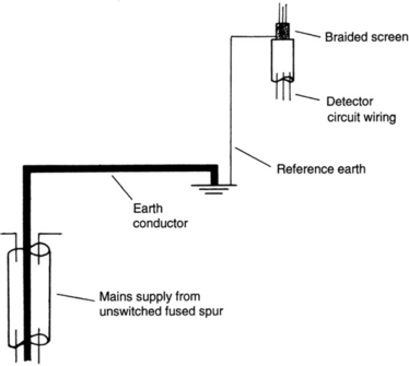
• never confuse the protective conductor, i.e. the mains earth, with any reference earth and always ensure that metal enclosures are correctly earthed.
A competent person is one who can demonstrate by acquisition of a recognized qualification, or experience or knowledge, that he or she can work safely on electrical supplies. A competent person also recognizes the limits of his or her expertise and will not undertake work that he or she is not trained for.
The removal of earthing conductors is extremely dangerous because the bond between all exposed metal in a premises and the final earth position ensures that an electrical path exists that will provide current leakage protection in the event of a short circuit. The removal of an earth conductor can mean that part of the building can become ‘live’ with the potential to kill.
Reference earths provide a path for induced current to dissipate from, for example, the braid of a shielded cable. These reference points are deliberately taken to earth at one point to ensure that earth loops are not set up in the shield. However, the size of these reference wires is small compared to the size of a conductor that is needed to carry sufficient current to blow a fuse or operate an RCD, and it is important to understand the differentiation between them. This is clear by reference to Figure 8.2.
The tests that must be performed and recorded as part of the commissioning process under the Electricity at Work Act can be seen as:
• a visual inspection of the mechanical protection of cables and housings;
• an insulation resistance test;
We may conclude that safety is achieved by ensuring that the mechanical protection of the cables is intact and that the insulation between conductors and between the conductors and earth is within the requirements of the regulations. Also, the continuity of the earth conductor must not present a resistance in excess of that allowed by the regulations, and the conductors must be connected to the appropriate terminals with respect to polarity.