Chapter 4
The Photovore
I’ve been interested in light-following robots, or photovores (“light-eaters”), as they’re called, ever since I saw my first BEAM robotic creations. BEAM robots use elements of biology, electronics, art, and mechanics to make realistic mechanical creatures—a photovore would fit perfectly into the right ecosystem.
At its simplest, a photovore uses photoresistors to “look” for the brightest light in the area and then moves in that direction. Many photovores are powered by solar cells, so it’s in their best interest to find the brightest spot around. Once they find it, they sit and recharge until the light moves, and then they follow it again, repeating the process.
It’s possible to replicate this light-following behavior with your Omega2, using a few photoresistors, an analog-to-digital converter, and a small robotics platform. I think it’s a good project, because even if you don’t plan on making your Onion mobile, you’ll understand the process of reading and reacting to external sensors, which again harks back to the O2’s IoT origins.
Parts
For this project you’ll need a few extra parts in addition to your Onion. You’ll be using the power dock and the relay expansion board we played with earlier. You’ll need four photoresistors (Figure 4-1), which we’ll use to measure light levels. You’re going to need an ADS1115 16-bit ADC breakout board, available from either Adafruit or Amazon (Figure 4-2). This board is necessary because the Onion does not have an onboard analog-to-digital converter chip, which means that without a little help, you won’t be able to read the values coming from the photoresistors. You’ll also need a few jumper wires, four 4.7KΩ resistors (or about that value), a breadboard (or several), and lastly, you’ll need some sort of mobile robotics platform.

Figure 4-1: Photoresistor

Figure 4-2: ADS1115 ADC board
If you’ve read my book on the micro:bit, you may be aware that I really like DFRobot’s Turtle platform (Figure 4-3) as an experimental base for small robots like this one. It’s not particularly expensive, and it’s easy to connect its motors to whatever platform—Arduino, Omega2, micro:bit—you may happen to be playing with at the time.

Figure 4-3: DFRobot’s Turtle platform
The Voltage Divider
Before we build the actual robot, let’s look at how we read the values from the photoresistors.
A photoresistor is a semiconductor that changes its resistance depending on the amount of light falling on it. The easiest way to set it up is as part of a voltage divider, in series with a regular resistor (Figure 4-4).
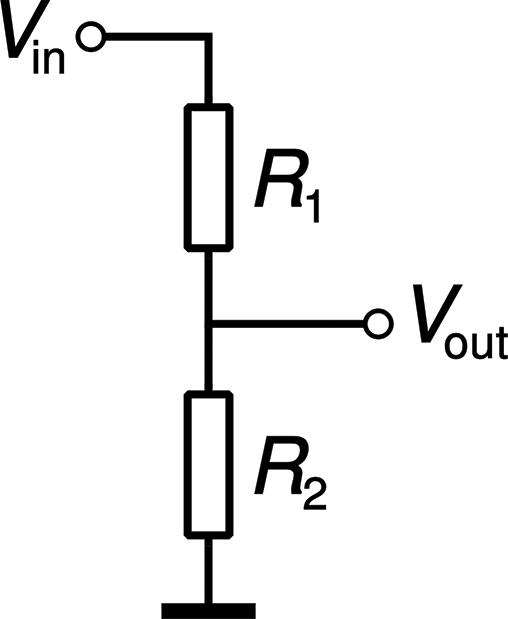
Figure 4-4: Voltage divider
If you’d like to try this without your Onion, it’s an easy circuit to create and play with. On a breadboard, place a resistor and a photoresistor in series. Connect the positive leg of a voltage source, such as a 9V battery, to the outer leg of the photoresistor. Connect the negative leg of the power to the outer leg of the resistor. Finally, connect a wire to the junction between the photoresistor and the resistor. You should end up with a setup similar to the one shown in Figure 4-5.

Figure 4-5: Voltage divider setup
Now connect your multimeter to the two wires coming from the breadboard and set it to measure resistance. Wave your hand back and forth over the photoresistor, and you should be able to watch the value of the resistance change as you do.
In our case, we’ll substitute our photoresistor for R1, and R2 will be our 4.7KΩ resistor. Vin will be 3.3 volts from the Omega2, and Vout is what we’ll measure. As the resistance changes with the light, the value of Vout will change, increasing as the light increases. If we were to put the photoresistor in the place of R2, Vout would decrease as the light increased.
That’s how our photovore will work: we’ll space four photoresistors around the perimeter of the bot’s body, and periodically measure the light at each one. If one shows more light (has the highest value returned) than the others, we’ll move the bot in that direction.
Hardware Setup
Now that you know the theory behind it, let’s set up the photovore. Again, I’ll be using the Turtle as the platform, but feel free to use another platform if you have one.
First, you’ll want to set up your photoresistors, either on individual breadboards spaced around the perimeter or spaced evenly at the corners of one large one. The idea is to space them as far apart as possible and facing in four different directions. I used a half-sized breadboard and stuck it on top of the batteries used to power the motors, and then I placed the resistors at the four corners of the board. Since they’re flexible, you can then aim them in any way you like. Try to aim them so each is pointing in a completely different direction, but avoid facing them directly forward, back, and right and left. Rather, try to face them diagonally; if you think of the front of the bot as North, face the photoresistors toward Northeast, Northwest, Southeast, and Southwest (Figure 4-6). This placement will allow the bot to “track” the light, zeroing in on light sources.

Figure 4-6: Placement of photoresistors
Once the photoresistors are placed, add a series resistor to each one the way we did in the preceding section. Using the breadboard’s ground and power lines, connect the 3.3V pin on your Onion to the breadboard, and then connect that to each individual photoresistor. Connect the O2’s GND pin to the breadboard and then connect that ground to each individual resistor (Figure 4-7).
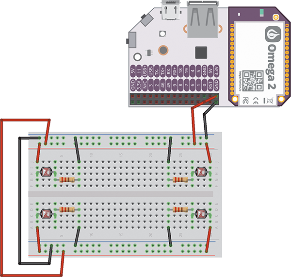
Figure 4-7: Connecting the photoresistors
Now plug your ADS1115 chip into your breadboard. You’re going to use eight jumper wires to connect it to your bot’s circuitry—four going to the Omega2, and four to the four photoresistor assemblies. Using Figure 4-4 as your template, connect Vout from the left-rear photoresistor assembly to pin A0, connect Vout from the right-rear assembly to pin A1, and connect Vout from the front-right and front-left assemblies to pins A2 and A3, respectively.
Now, using the other four jumper wires, connect the VDD and GND pins on the ADS1115 to the 3.3V and GND rails on your breadboard. Then connect the SCL pin on the ADS1115 to pin 4 on the Onion, and connect the SDA pin on the ADS1115 to pin 5 on the Onion.
The last thing you’ll need to do with your ADS1115 is connect a small jumper wire from the ADDR pin to the GND pin. The ADS1115 can have four different I2C addresses, allowing you to use up to four of them at a time. By connecting the ADDR pin to GND, you’re giving it the I2C address of 0×48.
Finally, you’ll need a power source for your Omega2 and one for your motors. This is one of the advantages of the external relay board; you can use a much larger power supply for your motors than your Onion could handle. I have a battery holder that holds five AA batteries, permanently attached to my Turtle, wired to the onboard switch. As for the Onion’s power, you can get small lithium polymer (LiPo) batteries pretty inexpensively from online vendors such as Adafruit and SparkFun; just make sure when you order that you get a battery with a 2-pin 2mm JST-H connector, which fits the plug on the Onion power dock expansion board. One nice thing about the power dock is that it will charge the battery for you if the microUSB plug is connected.
To connect the motors to the relay board, just remember that the relays are essentially switches that the O2 is flipping. The IN for each relay should be from the battery source, and the OUT should go directly to the motors. When the relay is OFF, the motor will get no power; when the Onion turns the relay ON, the motor will be connected to the power source.
That’s how your bot should be connected. Check out the Fritzing diagram in Figure 4-8 to make sure the connections to the bot are correct, and you should end up with something looking like Figure 4-9.

Figure 4-8: Schematic of photovore
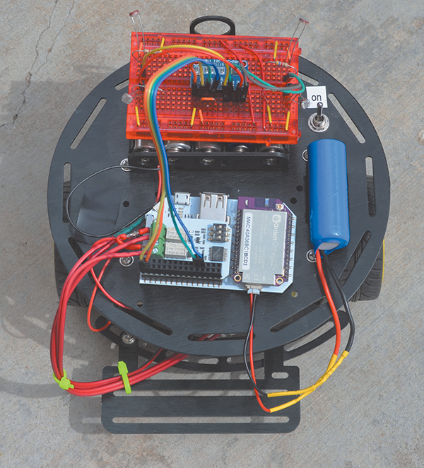
Figure 4-9: Assembled photovore
Software and Code
Once you’ve built your bot, the last thing to do is make sure you have the correct Python modules and then write the code.
First, let’s make sure we have all the Python modules we need. Luckily, Onion has released modules that allow users to interact with all the different expansion boards, in both C and Python. To start with, let’s install the I2C library. In your terminal, enter
opkg update
opkg install pyOnionI2C
opkg upgrade libonioni2c pyOnionI2C
That last line is sometimes necessary if your board’s software hasn’t updated quite right; mine was a bit wonky, and I was getting errors whenever I tried to run any I2C code. The upgrade line fixed the issues. Finally, you’ll also need to control the relay expansion, so install the necessary code with
opkg install pyRelayExpOnce that’s loaded, we’re ready to start our program. The nice folks at ControlEverything (www.controleverything.com) have figured out and shared how to communicate with the ADS1115 board via I2C, so we’ll borrow from their Python code. All the code necessary to communicate with the relay expansion board is available in the Onion documentation (http://onion.io/docs), including examples and instructions for the various functions for turning relays on and off. I’ll go into more detail as we write the program; right now the important thing to note with the relay board is the position of the three slide switches at the top right (Figure 4-10).

Figure 4-10: Address jumper switches
Those switches determine the I2C address of the board. As with the ADS1115 board, you can change the address of the board, allowing you to daisy-chain up to eight different boards. Make sure the switches are all in the OFF position, which gives your board the address of 0×27. Take note, as well, of the numbers of the relays; when you hook up your board, connect the right motor to relay 0 and the left motor to relay 1. This will ensure your code activates the correct motors to turn the right way.
The basic concept behind the light-follower is thus:
- Read the values from each of the four photoresistors, placed at the NW, NE, SW, and SE quadrants of the bot.
- Determine which shows the highest value.
If the highest-value photoresistor is in the front, briefly turn in that direction and then move forward. If the highest-value photoresistor is in the back, turn a bit longer in that direction, and then move forward.
- Repeat.
Remember that because we’re using relays to control the motors on our bot and not PWM, we can only make our motors go forward. (It also means that you can’t adjust the speed—they’re either fully ON or fully OFF.) This means that there’s no reverse; if your bot is facing one way and you want to go the opposite way, you’ll need to spin around so you’re facing the correct direction.
Let’s write our program. Start a new file, called lightFollower.py, on your O2.
from OmegaExpansion import relayExp
from OmegaExpansion import onionI2C
import time
import sys
if len(sys.argv) != 2:
    print "Need offset"
    exit()
Here we’ve imported the necessary modules, and we’re also checking for the address of the relay board. Remember that we set this address by sliding all the switches to the OFF position. Since this sets our board to an address of 0×27 (the int value of which is 7), we need to call our program with
python lightFollower.py 7. The 7 on the command line is passed into the program, where the sys.argv function reads it and learns the address (0x27, or 7) of the board we’re using in the program.
Continuing:
# Initialize relay board
addr = int(sys.argv[1])
relayExp.driverInit(addr)
# Initialize I2C
i2c = onionI2C.OnionI2C()
Here, both boards are initialized and are ready to go.
# Define movement functions
# Relay0 = right motor
# Relay1 = left motor
def turnRight90():
    relayExp.setChannel(addr, 1, 1)
    time.sleep(0.25)
    relayExp.setChannel(addr, 1, 0)
    return
The turnRight90() function works by using the setChannel() function, which takes as parameters the board’s I2C address, the channel (relay) address (1 in this case), and the state (ON or OFF—1 or 0) to which to set the relay. So to turn right, we send an ON signal to the left motor (remember, in order to turn right, you advance the left wheel), wait for a quarter of a second, and then turn it off again. If we need to turn for a longer time, we can simply call the function again.
def turnLeft90():
    relayExp.setChannel(addr, 0, 1)
    time.sleep(0.25)
    relayExp.setChannel(addr, 0, 0)
    return
def moveForward():
    relayExp.setAllChannels(addr, 1)
    time.sleep(0.5)
    relayExp.setAllChannels(addr, 0)
    return
Now that we’ve defined our movement functions, let’s start the body of the program.
while True:
    # Get values from photoresistors
    # Right rear = RR
    data = [0xC4, 0x83]
    i2c.writeBytes(0x48, 0x01, data)
    time.sleep(0.5)
    data = i2c.readBytes(0x48, 0x00, 2)
    RR = data[0] * 256 + data[1]
    if RR > 32767:
        RR -= 65535
This is the function we can thank the folks at ControlEverything for. To get values from the ADS1115, we first write an array of bytes (data) to the chip at address 0x48. We then wait for half a second and read the response. Finally, we convert that response to an integer we can use. Because the ADS1115 has four channels (A0, A1, A2, and A3), we specify the channel we’re reading and writing from with the 0xC4 part of the data array. That changes when we read from the other channels, but the rest of the code remains the same. Continuing:
    # Left rear = LR
    data = [0xD4, 0x83]
    i2c.writeBytes(0x48, 0x01, data)
    time.sleep(0.5)
    data = i2c.readBytes(0x48, 0x00, 2)
    LR = data[0] * 256 + data[1]
    if LR > 32767:
        LR -= 65535
    # Left front = LF
    data = [0xE4, 0x83]
    i2c.writeBytes(0x48, 0x01, data)
    time.sleep(0.5)
    data = i2c.readBytes(0x48, 0x00, 2)
    LF = data[0] * 256 + data[1]
    if LF > 32767:
        LF -= 65535
    # Right front = RF
    data = [0xF4, 0x83]
    i2c.writeBytes(0x48, 0x01, data)
    time.sleep(0.5)
    data = i2c.readBytes(0x48, 0x00, 2)
    RF = data[0] * 256 + data[1]
    if RF > 32767:
        RF -= 65535
Now to determine the brightest value:
    top = "NONE"
    if LF > RF and LF > LR and LR > RR:
        top = "LF"
    elif RF > LF and RF > LR and RF > RR:
        top = "RF"
    elif LR > LF and LR > RF and LR > RR:
        top = "LR"
    elif RR > LF and RR > RF and RR > LR:
        top = "RR"
And now that we’ve found where the light is, let’s move toward the light (sounds vaguely ominous, doesn’t it?):
    # Determine which way to move
    if top == "RR":
        turnRight90()
        turnRight90()
        moveForward()
    elif top == "RF":
        turnRight90()
        moveForward()
    elif top == "LF":
        turnLeft90()
        turnLeft90()
        moveForward()
    else:
        turnLeft90()
        moveForward()
And that’s the whole program. It’s also available at https://github.com/wdonat/jumpstarting_onion/blob/master/Chapter4/lightFollower.py.
You’ll notice that the else statement at the end handles any unforeseen situations, like LF equaling RR or something equally bizarre; if that’s the case, the bot will turn a bit to the left, move forward, and then take another reading. Also note that if the light is behind our bot, we call the turn function twice, so that it’ll turn all the way around and be facing the right way.
To run your program, set your bot down on the floor, plug in your battery, and let it power up. Then go over to your desktop or laptop connected to the Onion’s network. Log in either via SSH or with the console, and in the terminal, enter
python lightFollower.py 7Your bot should start roaming around, seeking out the brightest light in the room. It will not stop, however, when it finds the light, so don’t be surprised when before long it just kind of goes in a circle, since the readings from the photoresistors can vary quite a bit over time.
There are a few things you can do to add to and improve this code. The first thing you may want to consider is “smoothing out” the readings from the photoresistors, since they seem to wiggle around quite a bit. This could be done by taking a few readings over the course of a second or two and averaging them out. Another thing to try would be accounting for scenarios where both resistors in the front, for example, read the same; in that case, the bot should just move straight forward. The Omega2 can also use a webcam; it might be interesting to see a live view of what the photovore sees. Since the Omega2 is already a web server, you could stream the video live if you wanted to.
That concludes our introduction to the Onion Omega2. I hope I’ve managed to give you a good overview of this cool little board and everything it can do, and also given you a few ideas to go forward with its capabilities. Have fun with it, and I look forward to seeing what you come up with!