
This chapter is, in essence, a shopping list of the tools, parts, and software you’ll need to do the projects in this book. Most of the parts are common, and you probably have some in your junk box. A few aren’t worth getting anywhere else. I’ll list the kinds of gear that has the parts we need, but these lists are certainly not the only places to look.
Some parts are best purchased new, and I’ll list sources for them. You should know that I live in the continental United States, and my usual suppliers are nearly all in my country, which saves me postage. I’ve taken care to name only suppliers I’ve dealt with personally or large-scale operations I would buy from without trepidation.
If you are not in the continental United States, you can still use the websites that I list to look at the parts, but it will probably be cheaper for you to use suppliers in your own country to deliver them.
As for tools, if you have some or all of the tools on this list, great. No need to buy new ones. If not, I’ll go into how to pick good ones without breaking the bank.
All the software and information listed are free, and many are open source.
Tools and Supplies
Science officers from certain starships may be able to build computers from stone tools and animal hides, but I'm here to tell you that it's easier with the right tools and supplies.
An Arduino
We’ll be building an Arduino-compatible device called the Cestino. (That’s Italian for recycling bin.) To build it, ironically, you need an Arduino. I developed the Cestino with an Adafruit DC Boarduino and an Arduino Mega but, except for the Leonardo, nearly any Arduino or any fully compatible clone that can handle 5v circuits will do.
If you don’t already have an Arduino, then there are some questions to consider. First, can you solder? Second, do you want to be able to use Arduino shields, which are add-on boards that require the standard Arduino pin arrangement?
The Cestino will not have the standard pin layout, and it cannot be used with shields without a lot of jumpering and reworking of code.
If you can solder, and you don’t care about shields, I strongly recommend Adafruit’s USB Boarduino kit. Once you solder it together, it can plug directly into your breadboard, and you can jumper it to the Cestino’s breadboard sockets with ease. These are available from Adafruit ( http://www.adafruit.com ).
If you don’t want to solder, or if it will save you a bundle to order in your home country instead of overseas from the United States, but you still don’t care about shields, then the Arduino Nano will do all the same things as the Boarduino, and they come preassembled. They should be available at the usual Arduino (now Genuino) distributors, which are listed here: https://www.arduino.cc/en/Main/Buy . Make sure that the one you buy comes with its pins already soldered.
If you do care about shields, I suggest an Arduino Mega 2560 or an Arduino Uno R3. Like the micro and nano listed earlier, they should be available at the usual Arduino distributors. They are also the most commonly cloned boards, so non-Arduino-branded alternatives may be cheaper and easier to obtain.
Solderless Breadboards
All the projects in this book , as well as the Cestino itself, will live on solderless breadboards (Figure 1-1). If you’ve not encountered these before, they consist of a plastic case drilled with holes every 1/10th of an inch (2.54mm) surrounding a central trough. Each row of holes is connected together under the plastic case so that an IC plugged into the central trough has several holes beside each pin so you can plug wires or other components in and connect them to the pin.

Figure 1-1. Solderless Breadboard
The most common size of solderless breadboard is 6.5 inches by 2.1 inches (165.1 mm x54.36 mm) with 830 tie points (holes.) You’ll need two of these, preferably the kind that can snap together along the long edge. While the pin spacing is standard and the power busses along each edge are usually standard, the connectors to snap two or more boards together are anything but. Make sure that both boards are the same brand if you have to order them.
The only extra feature on these boards that’s really useful is to have the pin rows numbered. It’s not absolutely essential, but you’ll be working with ICs with 40 pins on a side at times, and IC makers love to put the power and ground connectors right next to each other. For sanity’s sake, I urge you to pay the tiny amount extra it costs to get labeled boards. You can also order a pair of these breadboards connected together with a metal backing and nice rubber feet to keep them from sliding off your workbench, with or without a built-in power supply, but these are much more expensive.
Solderless breadboards are available at Mouser ( http://www.mouser.com ), Digikey ( http://www.digikey.com (although it’s harder to find the cheap ones there), Adafruit, and so on. They’re a standard tool for prototyping circuits, so your usual electronics suppliers should have them. You might consider shopping surplus dealers like MPJA ( http://www.mpja.com ) as they sometimes have solderless breadboards considerably cheaper. It’s conceivable that old boards from the junk box might have corrosion in the tiepoints that would cause problems, or that the board has been used so much that the tiepoints are loose. They do wear out .
Jumpers (Optional)
A jumper is, in its most basic form, a piece of wire with two bare ends for connecting tiepoints of your breadboards together or to connect tiepoints to sockets on your Arduino.
You don’t actually have to buy jumpers like the ones in Figure 1-2. You can make your own out of hookup wire. When you get to the chapter on building the Cestino, you’ll see I did exactly that for the Cestino’s wiring, mostly to make it neat and easily discernible from the project wiring in the photographs. But make no mistake. Stripping each jumper on both ends is tedious. I recommend a set of premade jumpers with hard connectors at each end for easy grabbing. These are available at Mouser and Jameco, but they’re very expensive there. Adafruit has them at a much more reasonable price. Most hobbyist electronics shops sell these as well. The more colors they come in, the better. If you're buying them, you want male-to-male jumpers.

Figure 1-2. Jumpers
Jumpers wear out.
Maybe I abuse my jumpers, pulling them out from the middle instead of the molded connectors on each end, but I had several jumpers turn up bad during the course of developing these projects and the Cestino itself, and spent several frustrating hours debugging software problems that turned out to be bad jumpers. If your jumpers have been around a while, and something just doesn’t seem to work, test the jumpers for continuity .
Hookup Wire
You need hookup wire (Figure 1-3). I recommend using it for the standing wiring of the Cestino, to keep it out of the way, if for no other reason. It also looks nicer. Also, sometimes you need a jumper of an unusual length, and having some hookup wire to make your own is very handy. There are only a couple of important specifications.
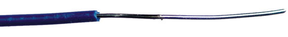
Figure 1-3. Hookup Wire
The wire must be 22AWG—gauge—a.k.a. 0.644 mm. The wire must be solid core. That is, it must have a single bendable copper wire inside, not a lot of little strands. They do, I’m told, make prebonded wire, which is stranded wire tinned along its length with solder. I’ve not tried it yet, but I’m told it makes fine, long-lasting jumpers. The bottom line is that the wire has to be rigid enough to push into the tiepoint reliably.
You’ll need at least two different colors of wire, black and something else. If your electronics supplier has a multicolor pack, I’d strongly urge you to get that. It’s easier to keep data lines separate from power, ground, and reset when they’re different colors.
Nearly any electronics hobby shop will have this kind of wire. In quantity it gets heavy, so I don’t recommend mail-ordering it, but if you must, I suggest Microcenter ( http://www.microcenter.com ) for the six-color kit from Elenco (I have this), or the similar kit from Adafruit .
A Multimeter
A multimeter (Figure 1-4) is a handy way to see inside a circuit and look for basic functionality. You need one. If you already have one, great .

Figure 1-4. An Inexpensive Digital Multimeter
I have a bunch: a Radio Shack folding analog meter from the early 1990s, a $70 Elenco digital multimeter from about 2004, and a new $11 MCM digital multimeter I picked up at my local Microcenter. For the purposes of these projects, pretty much any multimeter will work, but you do need to make sure that the resistance tester doesn’t put more than about 5 volts into the circuit being tested, or you can fry sensitive components. One mega-ohm of impedance should be enough—more is better. None of the circuits we’re working with are especially high impedance themselves. (Impedence is the AC version of resistance. For some components, it changes over frequency. At the frequencies we’re dealing with through most of this book, the difference doesn’t matter.)
If you don’t already have a multimeter, there are some considerations you should make before buying. The traditional view of tools is that if you buy good tools once, you can use them for a lifetime. That’s still true, but it’s expensive. If you want to go this route, head to https://www.youtube.com/watch?v=gh1n_ELmpFI , EEVblog’s Digital Multimeter Buying Guide. Watch the whole thing. I learned a lot when I did. Good, well designed, safe meters start at about $70, and the sky is the limit.
Really, we’re dealing with low power circuits. The maximum voltage any of the projects in this book should ever see is 12v, and that’s only in chapter 9, the ATA Explorer, to power the hard drive spindle motor. As long as you promise never to plug your meter into wall power, no matter how much the documentation says it can handle it, a cheap meter will do the job just fine.
The specs it must have are: at least 1 mega-ohm of impedance, so you can peek at the voltage of a logic line without changing it; a resistance/ohms setting that doesn’t throw out more than 5 volts (less is better); a continuity beeper, that beeps at resistances of a few tens of ohms; and it needs to take normal batteries, such as double or triple As or a standard 9-volt battery. Cheap meters tend to eat batteries, so their batteries should also be cheap.
Doing a web search right at this moment, I found meters that look promising at Harbor Freight ( http://www.harborfreight.com ) and in my local Walmart, ( http://www.walmart.com ), but if you want to spring for a better one for not much more money, I’d look at Sparkfun ( http://www.sparkfun.com ) or Adafruit. The latter two can probably tell you what the impedance and ohms testing voltage are, whereas the former are unlikely to know .
Screwdrivers
There are a couple of uses for screwdrivers in the projects in this book. The one that makes them a requirement is (gently) prying ICs off the breadboard when you’re done with them, so you’ll need a small, flat-bladed screwdriver for that. Disassembling junk, by contrast, may require quite an assortment of screwdrivers. If you’re buying new, most hardware stores sell inexpensive assortments of screwdrivers at a discount price, with a lifetime warrantee. If there’s no warrantee, it means they’ve made them out of such cheap steel that they’ll bend or strip the head of the screw the first time you use any force on one. I really recommend against buying these online, as they are quite heavy, but if you insist, Home Depot has a six-piece set in their Husky brand. I have a couple of those ( http://www.homedepot.com ). As you’re probably expecting by now, Adafruit has screwdrivers, too.
Wire Cutters/Strippers
Unless the car has one wire to splice and you will be eaten by plague bunnies right now if you don’t get the thing running, don’t use a pocket knife to cut and strip wire. It’s bad for the knife, and worse for your thumbs.
Wire cutters and strippers (Figure 1-5) are the right tool for the job. Fortunately, after screwdrivers, pliers, and duct tape, they’re the most common tool on Earth. You probably have at least a couple pairs of wire cutters already. Any of them will do the job for cutting.

Figure 1-5. Wire Cutters and Strippers
Stripping wires is a different question. I’ve been known to strip wires with my wire cutters in a pinch, and for thick wires it works ok. On 22 AWG wire, not so much. If you nick the copper inside the insulation, the wire will break after only a few bends. You want some kind of wire stripper. The simplest are a cutter with a notch sized to the copper itself. More complicated ones cut the insulation and remove it in one motion. Pick the kind you like.
A further consideration is that wire cutters and especially wire strippers wear out. While we’re not asking a lot for even dull cutters to cut 22 AWG wire, the wire stripper needs to do the job smoothly and neatly or it defeats the purpose. I wore out the (really cheap) wire cutters and strippers in Figure 1-5 in the process of writing this book .
If you’re buying new, I suggest getting separate wire cutters and strippers. For the wire cutters, flush cutters are a good choice. They’re cheap, sharp, and when you move on to printed circuit boards, you’ll need them anyway. Wire strippers come in a myriad of shapes and sizes, so assuming that they have a setting for 22-gauge wire, pick the kind you like. Mouser and Digikey carry both, as do Adafruit, Sparkfun, and so forth. Name brands cost more and usually last longer.
USB to 5v TTL Level Serial Cable
You need an FTDI USB to 5v TTL level serial cable (Figure 1-6). What, you ask, is that? Read on .

Figure 1-6. USB to 5v TTL Level Serial Cable and FTDI Friend
The earliest Arduinos communicated with their host computers over RS-232 serial. RS-232 is a very old protocol, dating back to 1962. It’s the kind of serial line we used to connect terminals to minicomputers with, and in more recent times we connected modems to computers with them. The ATmega and AVR micro-controllers used in Arduinos usually have the hardware to generate these signals built in. RS-232 is slow, but it’s simple, and fairly robust, not least of which because its signal voltages are as large as +15 volts for high and -15 volts for low. Therein lies the first of our problems.
The ATmega 1284p microcontroller, like most of its ATmega and AVR relatives, operates at about five volts. The voltage on any input can be no higher than 1 volt above the operating voltage. If we feed raw +-15 volt RS-232 to any pin on the ATmega 1284p, the result will likely be smoke and a damaged or dead microcontroller. Even if it could handle the voltages coming in, the computer on the other end is expecting +-13 volts (the most common real voltages in PC RS-232 ports), and the signals are coming out of the microcontroller are inverted anyway.
The solution to this problem is a level shifter, either as a dedicated IC, or a network of transistors and capacitors that shifts the signals up on transmit and down on receive. The original 2005 Arduino used this latter method, and if the Cestino were communicating to the host computer over RS-232, the Cestino would need a level shifter, too. It doesn’t have one because of the second problem .
RS-232 ports are rapidly fading into extinction. Macintosh computers were the first to be too cool for RS-232, but the venerable ports have largely vanished from laptops and notebooks, and were never present on tablets. They’re still occasionally found on desktop PCs, although they may not be wired right, and boards to add them are becoming few and far between. The world has gone to USB. Sadly, the ATmega-1284p doesn’t speak it.
One thing I’ve noticed in the time I’ve been tinkering in electronics: when there’s a widespread problem or group of problems, someone will make an IC that solves it or them. In the case of translating inverted TTL level RS-232 signals to USB, there are several. The most common is made by a company called FTDI, and they make a cable that plugs into your USB port, powers the internal conversion chip, and generates inverted, 0-5v ttl level RS-232 signals that the microcontroller can understand. Because USB also provides power, in the form of a +5 volt line, which is exactly what the microcontroller needs, the Cestino is powered by USB as well. This, then is the USB to 5v TTL Serial cable you’re looking for. But there are other solutions.
Adafruit gets mentioned a lot. They’re one of the North American distributors for Arduino, and they have these cables. They also have a little board of their own design they call the FTDI Friend, which does the same thing, but isn’t built into the cable. Better still, the FTDI friend comes with a set of extra-long pin headers for plugging into your breadboard and then plugging into the FTDI friend. It also comes with LEDs tied to the transmit and receive lines so you can see when the Cestino is communicating.
If you already have an FTDI Serial TTL-232 cable, as I do, you can either get a strip of protoboard and solder two sets of pins to it, connected together in pairs and use this to plug the cable into your breadboard, or you can order the extra-long pin-headers from Adafruit or Schmartboard ( http://www.schmartboard.com ) and plug them in without soldering. I bent mine to a right angle so the connector wasn’t quite so precarious.
There are two flavors of FTDI cable: the 5-volt version and the 3.3-volt version. You need the 5-volt version. The FTDI Friend is, by default, set up to provide 5-volt power and 3.3-volts on the communication lines, which is fine.
If you’re buying new, get the FTDI Friend. These can be had at Adafruit, of course, and second-sourced at Evil Mad Scientist ( http://shop.evilmadscientist.com ). Similar boards can also be found on the Arduino store ( https://store.arduino.cc/ ) and Seeed Studio ( http://www.seeedstudio.com ). These do not, however, come with the extra-long pin headers. One could certainly unsolder the pin sockets and solder normal pin headers to these boards instead. If you by the FTDI Friend or similar board, you will also need a standard USB cable with a Mini-B 5-pin connector on one end .
If you want the more traditional cable and you’re okay with figuring out how to connect it to your breadboard, Adafruit has them, Sparkfun has them. Mouser has them for about twice the price.
Optional: A Universal Programmer
A universal programmer, also known as a ROM burner, allows you to place programmable ICs in it, and program them. It will not work directly with the Arduino software, and if everything goes smoothly you shouldn’t need one for any of the projects in this book. (Although having one does make the EPROM explorer a lot more fun.)
I’m including it here because once in a while the bootloader installation process goes off the rails, and leaves the ATmega1284P “bricked”—caught in a catch-22 situation where it’s configured wrong and can’t communicate. Being able to reset the ATmega to its factory state will fix it, and a universal programmer is the tool for the job. If you have one, and it can program the ATmega1284P, you’re good to go. If you don’t have one, and you’d like one, make sure that the one you’re looking at can also program the ATmega1284P, among other things. Universal programmers can cost hundreds or thousands of dollars from companies you’ve heard of in electronic supply houses.
By contrast, I have a MiniPro TL866 universal programmer that I got directly from China on Ebay. It cost about $60 plus shipping, and I’ve been quite satisfied with it. I should mention that the TL866 only has windows software, but it runs nicely in VirtualBox under Windows 7 and 10. There is also open source software available for the TL866 ( https://github.com/radiomanV/TL866 ) but I’ve not used it at any length .
Software and Documentation
This book is mostly about hardware, but it’s software and documentation that make the hardware useful. This isn’t a comprehensive list of either one—there are more things to download in the projects themselves—but here’s what you need to get started.
Arduino 1.6.5 or Later
You need the Arduino software. We will be using Arduino 1.6.5. Later versions should work unless they change the configuration file layout again. The best place to get it is https://www.arduino.cc/en/Main/Software . If you already have Arduino installed, that’s fine, but make sure it’s version 1.6.5 or later. It will say in the top bar of the Arduino window.
Note
Linux users, your Linux distribution may provide a version of Arduino, but particularly if your distribution is based on Debian, it’s probably way out of date. I strongly encourage you to go to the Arduino site listed earlier and download the current version. Versions prior to 1.6.5 won’t work with the Cestino.
ATmega1284p Data Sheet
You need the datasheet on the Atmel ATmega1284p. It’s here, as of this moment, on Atmel’s Site: ( http://www.atmel.com/images/doc8059.pdf ).
Big companies do occasionally reorganize their websites, so if you can’t find it, do a web search on ATmega1284p data sheet. I strongly suggest downloading and saving a copy, as with all the datasheets you download, but it’s 372 pages long, plus appendices, so for now, you only need to print page 2, where the pinout diagrams are.
Texas Instruments 74xx00 Data Sheet
We’ll use the 74xx00 quad-nand gate IC in a project, but it’s also used in discussions of how to read datasheets. The TI datasheet is well written and well organized, and while there are lots of 74xx00 datasheets out there, the TI one is the one to get. It’s available on Texas Instruments’ website: http://www.ti.com.cn/cn/lit/ds/symlink/sn74ls00.pdf . It has a part number of SDLS025B.
Calculator
Any calculator will do. If it is a scientific or programming calculator that can translate in and out of binary, it might save you some work. The best of these run as applications on your computer, or your phone.
Optional: Adafruit Circuit Playground/Electrodroid
Although it’s not necessary, if you have an IOS (Apple) smartphone, Adafruit’s Circuit Playground is free and extremely useful for calculating circuits, working out resistors, and so on. I’ll tell you how to do these all by hand, but this isn’t school, so you can use an app if it’s easier. For Android users, there’s Electrodroid, which appears to do many of the same things .
Parts
Parts for these projects can come from a wide range of sources. New is fine, used parts are usually okay. Some parts aren’t worth harvesting used.
A Word On Resistors
A resistor is a device that conducts electricity but not very well. As a result, it converts some of the energy passing through it into heat. On the face of it, it doesn’t seem like resistors would be very useful, but they are the most common electronic component of all. They come in a wide array of packages, but the most common are axial lead resistors with the values painted on, like the ones in Figure 1-7.

Figure 1-7. Resistors
Thanks to Ohm’s and Kirchoff’s laws, we can use resistors to reduce the voltage of a given circuit. We can use them to limit the current of the circuit. More miraculously, we can raise the voltage of a circuit relative to ground by putting a resistor between the circuit and ground. We’ll get into Ohm’s and Kirchoff’s laws in Chapters 3 and 5, and these applications will make more sense, but for now it’s important to understand that resistors deal in ohms (resistance) and watts (energy or heat).
Resistors are also cheap. Really cheap. Resistors are so cheap that they’re not worth harvesting from junk, and even if your junk box has loose resistors that are old, with badly corroded leads, you might want to consider replacing them. In any case, when dealing with resistors, it’s a good idea to switch your multimeter to its ohms (Ω) setting and make sure the resistor is reasonably close to its advertised value.
Resistors are measured in ohms, named after the german physicist Georg Simon Ohm, who wrote Ohm’s law. This is the symbol for ohms: Ω.
The resistor on the left is a 1 watt resistor. The one on the right is a 1/4 watt, which is the type we’ll be using for these projects. They’re the same resistance value, but the one on the left can dissipate four times more energy as heat before it burns up than the one on the right.
Tip
Approach the full wattage ratings of resistors with caution. It’s a good idea to rate your resistors at twice the wattage you expect them to face.
Figure 1-8 is a handy table showing how you read the value of a resistor.

Figure 1-8. Resistor Color Codes
Looking at the resistors in Figure 1-7, you can see there are four color bands. Some resistors have five bands, but those are not very common. From the top, we have an orange, a second orange, and a brown band. If you look at the table in Figure 1-8, you see that the first two bands always indicate the numeric value, so orange orange is 3 and 3. The third band always indicates the power of ten to apply to the first two bands. Our third band is brown, which means 10 to the first power, or 10. 33x10 is 330 ohms. A 470k (thousand) ohm resistor would be yellow, for 4, violet for 7, and yellow for ten to the fourth, or 10,000, giving us a total of 47x10,000 or 470,000 ohms. And so on. The maximum this notation is capable of would be a resistor with three white bands, 99 times 10 to the 9th power, or 99 giga-ohms. By the way, a black band is always zero, so black-brown-black would be 0 1 times 10 to the zeroth power, which is 1, thus, 1 ohm.
The fourth band is the tolerance, that is, how close to its rated value is this resistor required to be. The widest tolerance is 20 percent, which means our 330Ω resistor might go range from 264Ω to 396Ω. These won’t have a fourth band at all. A silver band means the resistor is a 10 percent tolerance, so from 297Ω to 363Ω. Gold is 5 percent – 313Ω to 346Ω. Bear in mind that the price of resistors goes up dramatically from 0.8 cents each (in bulk orders of 5000) for 5 percent, quarter-watt, 330Ω resistors, to 1-7 cents each (in bulk orders of 5000) for 1 percent to 61 cents each (bulk orders of 5000) for .1 percent, which is as close a tolerance as Mouser will sell me. There are color codes for these too, brown and purple, respectively. Five to ten percent is fine for our purposes. I’ve chosen resistors that give us good, middle-of-the-road values in the circuits they’re in. If we’re ten percent high or low, the circuits will still work, and for digital applications rounding up to the nearest standard value of resistor will be fine, so if your calculations say you need 320Ω, use a 330Ω resistor.
I’ve called out what resistors you must have for each project, but the truth is, I recommend buying resistor kits if you’re just starting out. These are assortments of resistors, and they’re cheaper that way. The important specifications are: through-hole mounting (because surface mount won’t do any good on a breadboard) and 1/4 watt or 250mW (milliwatts – thousandths of a watt), mostly because anything else is either more expensive than you’ll need for digital electronics or too small to see easily.
Spark Fun has 1/4 watt resistor kits, ( https://www.sparkfun.com/products/10969 ) as does Amazon. I got mine at Radio Shack, back in the day.
A Word On Capacitors
Capacitors are simple, passive electronic devices that store electrical energy in the form of an electrostatic field. Literally, the charges are stuffed into the dielectric between two conductors, and once the capacitor charge equals the voltage of the charging circuit, the capacitor will cease to conduct until something changes—either the charging voltage goes higher, or lower.
Capacitors are very useful for separating alternating signals from direct current levels. If a capacitor is charged to the level of DC in a given wire, but an AC voltage is superimposed on the wire, only the AC voltage will emerge from the other side of the capacitor. If, instead, you want to keep AC out of a circuit, you put a capacitor from the circuit to ground, and most of the AC in the circuit will be shorted to ground. We use capacitors in both these ways in the Cestino build.
Capacitors are measured in Farads, technically, but a Farad is an enormous amount of capacitance and is not common in the wild. Usually in digital electronics, one sees microfarads—μF, and picofarads—pF. Occasionally things will be labeled in nanofarads (nF), and if your schematic is from before 1960, when the international system of units was adopted, you might see micro-microfarads (μμF). A nanofarad is 1000pF, and a micro-micro-farad is a picofarad. In Australia, a picofarad is sometimes called a puff .
Like resistors, capacitors are extremely common, cheap components that you see everywhere in electronics, in a wide variety of formats (Figure 1-9). Like resistors, they are not worth harvesting from old equipment. Although capacitors may also be labeled with color coding, it’s much more common for them to be stamped with a numeric value.

Figure 1-9. Capacitors
The capacitors in Figure 1-9 are both .1μF capacitors. The one on the left is a ceramic disk, rated at a thousand volts, the other is a tantalum capacitor rated at 50 volts.
The way you read this notation, 104, is the first two digits are the value, and the last digit is the number of zeros after it, in picofarads. So 104 is 10 times 10,000, or 100,000pF, aka 0.1μF.
Not coincidentally, 0.1μF capacitors are the only type we’ll be using in the projects in this book, usually to short AC noise to ground, although there’s one in the reset circuit of the Cestino as well.
If you’re buying new, I suggest getting a few dozen 0.1μF 50v tantalum capacitors. They’re tiny and easy to find room for .
Some Words on Junk
So if resistors and capacitors aren’t worth harvesting, what is? And what kinds of junk should you look in?
The best kind of junk for these projects dates back to the 1980s-1990s. In boards of that vintage, most of the chips are still of the through-hole variety—that is, their pins go all the way through holes in the board and are soldered on the back. Quite a few will be socketed, where they can be removed with a screwdriver. If you can find this vintage of equipment at yard sales and thrift stores, they’re the way to go.
As the years wore on and surface-mount (SMD) electronics and large scale integrated circuits (where more and more functions were packed in fewer and fewer ICs) became the norm. Through-hole ICs became fewer and further between. Nowhere did this happen faster than in computers.
Computers aren’t the only game in town, though. As the computer revolution spread, older (cheaper) ICs and through-hole manufacturing were—and are still—often used in other devices, like thermostats, car electronics, VCRs, and so on. These can be goldmines of old parts that are worth having. There is a catch, of course, and that is that you have to unsolder the parts. There are lots of tutorials online, but the upshot is it requires patience, a soldering station (so you don’t overheat the IC) and a hand-held, spring-powered solder-sucker. There are tutorials online for extracting ICs from old boards.
If you intend to do this kind of work on a regular basis, you might want to invest in a powered desoldering tool like the Hakko FR300. I have a Hakko 808, the older model, and a stash of spare parts for it. I wouldn’t go back.
The components I’ve called out are, for the most part, common as dirt (ROMs, 7 segment LED displays, tactile buttons, speakers, individual LEDs, ATA Hard Drives, etc.) and most are readily available new from big name electronics supply houses (Mouser, Digikey, and so on.) If you don’t have one, you might have to hunt around online, or ask friends for old ATA drives, as they’re pretty much extinct, and certainly not worth buying new. The same goes for old ROMs/EPROMS. You could certainly buy new EPROMs (EEPROMS will also work) but unfortunately they ship blank, and the project as designed won’t write to them. You’d be better off digging the BIOS chip out of an old PC motherboard, even if it’s a modern 4 or 6 pin type, and reading up on how it communicates. If it speaks SPI, a serial protocol, you’re in luck. The ATmega1284p has SPI hardware built in. The other possibility is that it speaks I2C, another serial protocol, for which there is an Arduino software library. This book is about tinkering. Don’t be afraid to tinker. This stuff is, after all, junk, destined for the recyclers.
If you really can’t find the parts for a given project, the important thing is to understand what that project is doing.
When you do find junk that seems like a good candidate, the first thing to do is look up the datasheet on that part. Most parts, especially as you reach back in computing history, are standard, and the datasheets are still around. You shouldn’t have to pay for them, either. If the part is soldered, you might want to look at the datasheet first, before you go to the trouble of unsoldering it. Parts designed for anything other than 5 volts won’t work for these projects.
Once you have the datasheet, save it. Datasheets have the habit of disappearing off the internet as a part goes more and more obsolete, or as companies get sold and resold and these ancient parts that haven’t been in production in years are deemed not worth adding to the new company’s website.
Parts by Project
If you are in the electronics store looking at this book and wondering what parts you need, project by project, you're in the right place. The same goes if you’re shopping online.
Cestino
The Cestino, star of this book and all the projects in it, is a mostly-Arduino-compatible experimenter’s system, built on a breadboard. In order to build one, you will need the components shown in Figure 1-10.

Figure 1-10. Cestino Parts
New Parts
One Atmel ATmega1284P sometimes called the ATmega1284P-PU microcontroller. You want the PDIP/40 pin DIP or through-hole version.
These are available at Mouser, Digikey, and Futurelec ( http://www.futurlec.com ). Futurelec’s shipping tends to be leisurely, but they usually have the best prices and a very wide selection. Amazon has them as well, but they’re charging a more than most other suppliers. These ICs seem to be quite robust, so only get a spare if you want one.
Warning
Some sellers also list the ATmega1284, sometimes known as the ATmega1284-PU. (Note the missing P before the hyphen.) It’s not quite the same microcontroller, and the Cestino firmware will not load on the ATmega1284. I have two of them that don’t work to prove it. The PU in both ICs refers to the PDIP (plastic dual in-line pins) package rather than the pico-power capabilities of the micro controller, as in the ATmega 1284P-PU
Four 0.1uF capacitors, any type. See: A Word on Capacitors.
One of these couples the reset circuitry to the TTL-RS232 cable to keep DC levels from being passed. The others are decoupling/bypass caps to keep AC noise out of the IC’s power supplies.
One 10kΩ resistor. See: a Word on Resistors.
This is the reset pull-up resistor.
One 330Ω resistor. See: a Word on Resistors .
This is the current-limiting resistor for the LED. (If your LED is a real weirdo, you may need to resize this. My board has a 220Ω resistor because I chose a very bright LED that has a higher voltage drop. All this is explained in Chapter 3.
Hookup Wire. See Tools and Supplies.
New or Used Parts
One 20MHz Full Can TTL crystal oscillator
This is the Cestino’s clock. Without it, the Cestino won’t do anything. Any brand is fine, and Mouser, Digikey, and Futurelec all have them for about the same price. Make sure you get the full can type as shown in the photo. I had two of these in my junk box. The one shown in the picture is the one that works. They’re not expensive. You might want a spare.
One Tactile button, momentary-on (only on while pressed).
Mine have big flashy plastic buttons on them, but it’s not a requirement. As always, you want a through-hole mounting. This is the reset switch for the Cestino. If you’ve looked ahead, there’s another one just like it used for the Morse Code Translator.
One USB to 5v TTL level Serial Cable/board/whatever. See Tools and Supplies.
This can’t be shared with your existing Arduino, as the Cestino gets its power from this cable.
One Arduino. See Tools and Supplies.
Used to burn the bootloader onto the Cestino .
Morse Code Practice Translator
The Morse Code Translator is a simple project rolled into Chapter 3, wherein we test the Cestino to make sure it works properly. Its parts are shown in Figure 1-11.

Figure 1-11. Morse Code Practice Translator Components
New Parts
One 100Ω resistor. See A Word on Resistors. A 330Ω will also work, but it's quieter.
New or Used Parts
One small speaker, 8Ω or higher.
If you solder, soldering some hookup wire to the tabs on the speaker will make it easier to connect to your breadboard, but twisting the hookup wire on tight will work. I sacrificed a jumper to connect mine. Literally any small speaker will do. If it’s designed for a car sound system or is much larger than your hand, it might not make enough sound to hear with the energy we’ll be giving it .
Larson (Memorial) Scanner
The Larson (Memorial) Scanner is a classic Arduino project named after the late TV producer Glen A. Larson. It's done here with a twist. Its components are shown in Figure 1-12.

Figure 1-12. Larson (Memorial) Scanner Parts
New Parts
Eight 330Ω resistors. See A Word on Resistors.
These are current limiting resistors to keep the LEDs from being fried, and the ATmega1284P from having its outputs overloaded. These should be good for any color of LED about this size If your LEDs are weirdos (very small or very large,) you may need to resize. Other colors than red are fine, and can use the same resistors, since their forward voltages are higher.
New or Used Parts
Eight LEDs, preferably the same size, shape, and color or one LED bar graph (any orientation) with at least eight LEDs in it. Common cathode or common anode bargraph LEDs will work, but the wiring will be different.
If you’re buying new, make sure to download and read the datasheet on your LEDs. They can’t have a forward voltage drop of more than 5 volts (that’s all the ATmega1284P can provide) and they need to be happy on less than 20mA each, so we don’t overload the ATmega1284P’s outputs or overall current limit. Don’t worry, I’ll explain in Chapter 4.
These can be bought new at Mouser, Digikey, SparkFun, Adafruit, and just about anywhere that sells electronic components .
Transistor Tester
The Transistor Tester is a simple project to get familiar with pulse-width modulation and analog inputs. Various transistors in different packages are shown in Figure 1-13.

Figure 1-13. Transistors
New Parts
Three 330Ω resistors.
These are the load resistors to convert the PWM pulses into a variable voltage.
Used Parts
Small signal BJTs (bipolar junction transistors) and/or Darlington transistors.
If the leads will fit in the breadboard, it has a chance of working. I have an assortment from Microcenter, but if there’s one part that should be in everyone’s junk collection somewhere, it’s these.
TTL Tester
7400 series TTL ICs have held the computer revolution together from their introduction in the 1960s right through today. The TTL tester explores these wonderful, simple ICs. (Figure 1-14)

Figure 1-14. 7400 Series TTLs
New or Used Parts
Any 74xx series logic IC of any vintage. 7400s, 74LS10, 74F? Bring ‘em on. As long as they’re 5-volt logic, at the speeds we’re going, they should all work fine.
If you must buy new, Futurelec has by far the best assortment. The 74xx00 quad-nand gate is the most fun, and we use it in another project anyway. Mouser and Digikey have these as well. As always, get the DIP, PDIP and/or through-hole versions.
Logic Probe/Injector
New Parts
2 680Ω resistors.
1 0.1uF capacitor.
New or Used Parts
1 74xx00 IC, where xx is F, LS, HCT, or any other type of 5v 7400 capable of sinking at least 1.5mA, and whose inputs go high around 2v.
If you bought a 74xx00 for the TTL Tester project, it’s perfect .
ROM /EPROM/EEPROM Explorer
The ROM/EPROM/EEPROM explorer lets you peek inside 8 bit ROM ICs, like the ones in Figure 1-15.
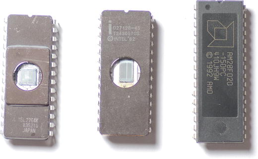
Figure 1-15. EPROMS and Flash
New Parts
One 0.1μF capacitor. This is used to decouple the ROM’s power supply from AC noise.
Used Parts
Any 8 bit parallel (multiple data lines) ROM, EPROM or EPROM. It must be happy on a single supply voltage of 5v. For EPROMs, this is anything made after about 1980, particularly 27xx series EPROMs, preferably not a 2716. Parallel EEPROMs and Flash will work too.
A datasheet for your ROM/EPROM/EEPROM/Flash. Their pinouts can be different, so you’ll need to look yours up.
There’s really no point buying EPROMs for this project new, as they will be blank, unless you have the optional universal programmer (See: Tools and Supplies). If you do have the programmer, or a friend does, any 2764 EPROM will work, and Futurelec has them, but unless the old school, quartz window EPROMS intrigue you as much as they do me, I’d suggest getting a 28C series EEPROM or 28/29F series Flash IC. They interact more or less the same way.
There’s a second setup and sketch in this project for writing to a 39SF020A flash, which is a common type and still readily available from supply houses today. If you’re buying new, look for this part number: SST39SF020A-70-4C-PHE. Many other types of flash IC will work, but may involve rewiring and/or extensive rework to the sketch to accomidate different commands, registers, or fussy timing .
ATA Explorer
The ATA explorer lets you look at the contents of an old parallel ATA/IDE drive. Components are in Figure 1-16.

Figure 1-16. ATA Explorer Components
New parts
40 pins worth of extra long pin headers, ideally in two rows of 20. These are available at Adafruit or Schmartboard.com . Make sure they’re the kind with equal lengths of pin on both sides of the plastic divider, just like we used on the Cestino itself for the TTL-232 connector .
Used parts
One ATA/IDE drive. Needs to be operational.
The sketch only knows LBA24, so the drive needs to be less than 128GiB in order to work. Drives from the late 1990s to the early 2000s are the best choices.
Notebook drives should work, if you have a notebook to desktop adapter.
1 40 pin PATA/IDE cable with two drive connectors and no twists.
One ATX power supply (Working)
Hard drives require 12-volt power for the spindle motor. Even notebook drives require more current in 5 volts than we can safely draw from the Cestino’s existing power system. Fortunately, any scrapped computer in the last 15 years or so will have an ATX power supply. Ideally, it will have a power switch in the back, but this isn’t necessary. The newer your ATX power supply is, the better, as the filter capacitors dry out over time, which makes for a noisy power supply.
Dice Device
This project builds a dice rolling device for a well known role playing game system popular in my youth. Parts shown in Figure 1-17.

Figure 1-17. D20 System Dice Device Parts
New Parts
2 330Ω resistors
Optional: 8 150Ω resistors (these improve readability of the display)
New or Used Parts
Two tactile button switches, momentary on. One for rolling the dice, one for setting the size.
Two 7 segment LED displays, any color, any size that will fit comfortably on the breadboard. Common Anode or Common Cathode are fine. One double-digit 7 segment display will also work. If you’re buying new, it will save you some rewiring of the project to get the LTD 4608JG, which is what I used.
1 ULN2803 or similar Darlington transistor array, or 2 TIP120 Darlington transistors.
Just about any NPN transistor capable of switching a continuous 80mA or more will do the job, with appropriate base and emitter resistors.
Z80 Explorer
The Z80 Explorer is the last and most complex project in the book. In it, we’ll hook an old 8 bit microprocessor (a Z80; see Figure 1-18) up to the Cestino, build it some virtual memory, and get it to execute some instructions.

Figure 1-18. Z80 Microprocessor and a Clone
New or Used Parts
Any “modern” Z84 prefix Z80 or fully compatible clone microprocessor. Its datasheet must list either “fully static design” or a maximum clock period of infinity. The D780C shown may work, according to the datasheet, but mine turned out to be dead.
Even though they were first released in 1976, Z80s are still cheap and plentiful, and available at Mouser and Digikey at speeds up to 20MHz. The 20MHz unit is twice the price of the 10MHz one, but if you are considering building a working computer around this CPU at some point in the future, get the 20MHz version. It makes old Z80 software fly. If you have a μPD780C or similar from NEC, it’s worth trying, at least.
Postage Is Not Your Friend
You’ve probably noticed that my list of suppliers overlaps a great deal from part to part. This is not an accident. I tend to use the same suppliers over and over again, and yes, reliability matters to me. The other reason I overlapped them is that shipping is expensive. It's very easy to pay more to ship tiny electronics components than the components themselves cost.
It’s a strange economy. Although your first instinct might be to shop around and get the lowest price for any given part, consolidating your orders into as few boxes as possible often saves more on shipping than the difference in part prices.
Summary
These are the parts you need for all the projects in the book. I'll list the parts again briefly in each project.