
1
MBB Service – Network Architecture
1.1. Initial architecture
1.1.1. Functional architecture
The functional architecture of the EPS (Evolved Packet System) network is depicted in Figure 1.1, at the point when the mobile attaches to its home network.

Figure 1.1. Functional architecture of the EPS network
The EPS mobile network consists of an EPC (Evolved Packet Core) network and an evolved universal terrestrial radio access network (E-UTRAN).
The E-UTRAN ensures the connection of the user equipment (UE), the resource allocation for the radio interface and the resource reservation when the mobile is switched from one cell to another.
The EPC interconnects the access networks, provides the interface to the packet data network (PDN) and controls the attachment of mobiles, the authorization to access the service and the establishment of bearers.
1.1.1.1. eNB entity
The E-UTRAN includes a single type of entity, the evolved node base station (eNB), which connects to the mobiles.
The eNB entity is responsible for the management of radio resources, for the control of the establishment of the data radio bearer (DRB), in which the mobile traffic is transmitted, and for its mobility management during the session (handover) which consists of a transfer of the DRB to another eNB entity.
This entity transfers the traffic data from the mobile (respectively from the SGW (Serving Gateway) entity) to the SGW entity (respectively to the mobile).
When the eNB entity receives data from the mobile or from the SGW entity, it refers to the QoS class identifier (QCI) for the implementation of the data scheduling mechanism.
The eNB entity can perform the marking of the DS (DiffServ) code point (DSCP) field of IP (Internet Protocol) header, based on the assigned QCI, for outgoing data to the SGW entity.
It performs compression and encryption of traffic data on the radio interface.
It performs encryption and integrity control of signaling data exchanged with the mobile.
It performs the selection of the mobility management entity (MME), part of the core network, to which the mobile is attached.
The eNB entity processes paging requests sent by the MME entity for their distribution in the cell corresponding to the radio coverage area of the eNB entity.
It also distributes system information of the cell, containing the technical characteristics of the radio interface and allowing the mobile to connect.
It uses the measurements made by the mobile to decide on the initiation of a cell change during a session (handover).
1.1.1.2. MME entity
The MME entity is the network control tower, allowing mobile access to the service and controlling bearer establishment for the transmission of traffic data.
The MME entities belong to a group (pool). Load balancing of the MME load is ensured by the eNB entities within a group that must have access to each MME entity of the same group.
The MME entity is responsible for attachment and detachment of the mobile.
During attachment, the MME entity retrieves the subscriber’s profile and the subscriber’s authentication data stored in the home subscriber server (HSS) and performs authentication of the mobile.
During attachment, the MME entity also registers the tracking area identity (TAI) of the mobile and allocates a globally unique temporary identity (GUTI) to the mobile which replaces the private international mobile subscriber identity (IMSI).
The MME entity manages a list of location areas (TAI) allocated to the mobile, within which the mobile in the idle state can move without contacting the MME entity to update its location area.
When attaching the mobile, the MME entity selects the SGW and PGW (PDN Gateway) entities for the construction of the default bearer, e.g. for the transport of IP packets containing SIP (Session Initiation Protocol) signaling or the data from Internet services.
For the construction of the bearer, the selection of the PGW entity is obtained from the access point name (APN) given by the mobile or by the HSS entity in the subscriber’s profile.
The source MME entity also selects the target MME entity when the mobile changes both cell and group (pool).
The MME entity provides the information required for lawful interception, such as the mobile status (idle or connected), the location area if the mobile is idle or the E-UTRAN cell global identifier (ECGI) if the mobile is in session.
1.1.1.3. SGW entity
The SGW entities are also organized into groups (pools). To ensure load balancing of SGW load, each eNB entity within a group must have access to each SGW entity of the same group.
The SGW entity forwards incoming data from the PGW entity to the eNB entity and outgoing data from the eNB entity to the PGW entity.
When the SGW entity receives data from the eNB or PGW entities, it refers to the QCI for the implementation of the data scheduling mechanism.
For incoming data from the PGW entity, and outgoing data from the eNB entity, the SGW entity performs the DSCP field marking of the IP header of the S1 and S5 bearers, depending on the assigned QCI.
The SGW entity is the anchor point for the intra-system handover (mobility within the EPS network) provided that the mobile does not change group. Otherwise, the PGW entity performs this function.
The SGW entity is also the anchor point for the inter-system handover in the PS (Packet-Switched) mode, requiring the transfer of traffic data from the mobile to the second- or third-generation mobile network.
A mobile in the idle state remains attached to the MME entity. However, it is no longer connected to the eNB entity, and thus the radio bearer and the S1 bearer, built between the eNB and SGW entities, are deactivated.
The SGW entity informs the MME entity of incoming data when the mobile is in the idle state, which allows the MME entity to trigger the paging towards all eNB entities belonging to the same location area (TAI).
1.1.1.4. PGW entity
The PGW entity is the gateway router that provides the EPS network connection to the PDN (Internet network).
When the PGW entity receives data from the SGW entity or the PDN, it refers to the QCI for the implementation of the data scheduling mechanism.
The PGW entity can perform DSCP marking of the IP header of the S5 bearer, based on the assigned QCI.
During attachment, the PGW entity grants an IPv4 or IPv6 address to the mobile. If the assigned IPv4 address is a private address, the entity PGW performs network address and port translation (NAPT), in order to translate the IP addresses and the TCP (Transmission Control Protocol) or UDP (User Datagram Protocol) port numbers.
The PGW entity constitutes the anchor point for inter-SGW mobility when the mobile changes groups.
It hosts the policy and charging enforcement function (PCEF) which allows the rules relating to mobile traffic data on packets, filtering, charging and quality of service (QoS) to be applied to the bearer to build.
The policy and charging rules function (PCRF), outside the EPS network, provides the PCEF of the PGW entity with the rules to apply when establishing bearers.
The PGW entity performs replication of the mobile traffic data within the framework of lawful interception.
1.1.1.5. HSS entity
The HSS entity is a database storing the data specific to each user. The main data stored include the identities of the users, the authentication parameters and the service profile.
When subscribing to the EPS network, the mobile is assigned a private identity (IMSI) which is associated with a service profile and a secret key (Ki).
The authentication parameters are used to control access to the mobile for attachment to the EPS network.
The service profile determines the services that the user has subscribed to.
1.1.1.6. PCRF entity
The PCRF entity provides to the PCEF entity, integrated in the PGW entity, the necessary information for the control and the charging of the traffic data (IP packets).
This information is stored in the subscription profile repository (SPR) during the creation of the subscription.
Traffic control includes the following:
- – association between a service data flow (SDF) and the EPS bearer;
- – blocking or allowing IP packets;
- – assignment of the QCI parameter to the EPS bearer.
The PCEF entity executes the rules provided by the PCRF entity to control the traffic flow and the charging.
The PCEF entity may relate to the PCRF entity a change in state of a service flow, as in the case of loss of radio coverage of the mobile.
The PCRF entity may receive a session request from the application function (AF) as in the case of the establishment of a voice or conversational video communication initialized at the IP multimedia sub-system (IMS).
The PCRF entity may provide the AF entity with information about events occurring in the mobile network as in the case of loss of radio coverage of the mobile.
1.1.2. Protocol architecture
The protocol architecture of the EPS network is described in Figure 1.2 for the control plane and in Figure 1.3 for the user plane.
1.1.2.1. LTE-Uu interface
The LTE-Uu interface is the reference point between the mobile and the eNB entity (Figure 1.4).
This interface supports RRC (Radio Resource Control) signaling exchanged between the mobile and the eNB entity, transmitted in the signaling radio bearer (SRB) and the mobile traffic data (IP packets) transmitted in the data radio bearer (DRB).

Figure 1.2. Protocol architecture: the control plane

Figure 1.3. Protocol architecture: the user plane
The RRC protocol performs the following functions: broadcasting information system, control of the connection, control of the radio bearer, control of the handover and transfer of measurement reports.
RRC signaling also provides transport of the NAS (Non-Access Stratum) signaling messages exchanged between the mobile and the MME entity.
Traffic data corresponding to an IP packet and signaling data corresponding to an RRC message are encapsulated by the data link layer, which is divided into the following three sub-layers:
- – PDCP (Packet Data Convergence Protocol);
- – RLC (Radio Link Control);
- – MAC (Medium Access Control).

Figure 1.4. Protocol architecture of the LTE-Uu interface
The PDCP is used for RRC signaling messages related to dedicated control and for IP packets, and provides the following functions:
- – compression of traffic data headers using the robust header compression (ROHC);
- – security of traffic data (confidentiality) and RRC signaling (integrity and confidentiality);
- – delivery in sequence of RRC messages and IP packets;
- – recovery of PDCP frames lost during the handover.
The mobile can simultaneously activate multiple PDCP instances, each instance corresponding to a data radio bearer or a signaling radio bearer.
The RLC protocol provides control of the radio link between the mobile and the eNB entity.
The mobile can simultaneously activate multiple RLC instances, each instance corresponding to a PDCP instance.
The RLC protocol operates in three operation modes:
- – acknowledged mode (AM);
- – unacknowledged mode (UM);
- – transparent mode (TM) for which no header is added to data.
The RLC protocol provides the following functions:
- – retransmission in the case of error via the Automatic Repeat reQuest (ARQ) mechanism, for the acknowledged mode only;
- – concatenation, segmentation and reassembly of PDCP frames in both the acknowledged and unacknowledged modes;
- – possible re-segmentation of PDCP frames, in the acknowledgment mode, during a retransmission of the RLC frame;
- – re-sequencing of received data in both the acknowledged and unacknowledged modes;
- – detection of duplicate data in both the acknowledged and unacknowledged modes.
The MAC protocol provides the following functions:
- – multiplexing RLC frames from multiple instances in a transport block;
- – allocation of the radio resources via a scheduling mechanism for both transmission directions;
- – management of retransmission in the case of error via the HARQ (Hybrid Automatic Repeat reQuest) mechanism;
- – management of the random access procedure.
The physical layer consists of two subsets, whose interface constitutes the physical channel:
- – for each transmission direction, the first subset comprises the error detection and correction codes and the rate adaptation;
- – for the downlink, the second subset comprises the modulation, the spatial layer mapping, the precoding, the resource element mapping and the inverse fast Fourier transform (IFFT) for OFDM (Orthogonal Frequency-Division Multiplexing) signal generation (Figure 1.5);
- – for the uplink, the second subset comprises the modulation, the mapping on the resource elements and the IFFT. The generation of the DFT-S-OFDM (Discrete Fourier Transform Spread OFDM) signal is obtained from a fast Fourier transform (FFT). Spatial layer mapping and precoding are implemented only for the LTE Advanced interface (Figure 1.6).

Figure 1.5. The downlink chain of transmission

Figure 1.6. The uplink chain of transmission
1.1.2.2. S1 interface
The S1 interface is a group of interfaces between the E-UTRAN and the EPC, and consists of the S1-MME and S1-U interface.
The S1-MME interface is the reference point between the MME and eNB entities for signaling. This interface supports S1-AP (Application Part) signaling.
The S1-AP protocol provides the following functions: establishment of the mobile context; establishment, modification and release of the EPS radio access bearer (E-RAB), built between the mobile and the SGW entity; management of the handover; and paging.
The S1-AP protocol also provides the transport of the NAS signaling exchanged between the mobile and the MME.
The S1-U interface is a reference point between the eNB and SGW entities. This interface supports a GPRS tunneling protocol user (GTP-U), which encapsulates the IP packet flow.
1.1.2.3. S11 interface
The S11 interface is the reference point between the MME and SGW entities for signaling via the GPRS tunneling protocol control (GTPv2-C).
The GTPv2-C protocol supports the following functions: managing the context of the mobile and the S1 bearer and notification of incoming data when the mobile is in the idle state.
1.1.2.4. S5 interface
The S5 interface is the reference point between the SGW and PGW entities for signaling via the GTPv2-C protocol and traffic data (IP packets) via the GTP-U protocol.
1.1.2.5. S10 interface
The S10 interface is the reference point between MME entities. This interface is used when the mobile changes group (pool) and the MME must be relocated. It supports GTPv2-C signaling.
1.1.2.6. SGi interface
The SGi interface is the reference point between the PDW entity and the PDN (Internet).
1.1.2.7. X2 interface
The X2 interface is the reference point between two eNB entities. It is activated when both eNB entities belong to the same group.
This interface supports the X2-AP signaling for the control plane (Figure 1.7), and the GTP-U protocol for the IP packet flow when the mobile changes cell (Figure 1.8).

Figure 1.7. Protocol architecture of the X2 interface: the control plane

Figure 1.8. Protocol architecture of the user plane during the handover based on the X2 interface
The tunnel established between the two eNB entities is unidirectional (from the eNB source to the target eNB). It makes it possible to transfer to the target eNB entity the received traffic data from the SGW entity. It is temporarily established during the handover of the mobile.
1.1.2.8. S6a interface
The S6a interface is the reference point between MME and HSS entities. This interface supports DIAMETER signaling.
The DIAMETER protocol allows the MME to recover the authentication data and the service profile of the mobile.
1.1.2.9. Gx interface
The Gx interface is the reference point between the PCRF entity and the PCEF of the PGW entity. This interface supports DIAMETER signaling.
The DIAMETER protocol allows the PGW entity to recover rules applying to the EPS bearer and to inform the PCRF entity of the termination of the session on the EPS network.
1.2. CUPS architecture
The CUPS (Control and User Plane Separation) architecture consists of separating the functions of the control plane (CP) and user plane (UP) from the SGW and PGW entities.
This separation allows the flexibility of deployment of the EPC, the equipment that can be distributed or centralized, and an independent scaling between the functions of the CP and the UP.
The initial SGW entity is reconfigured from an SGW-U (User) entity, connecting S1 and S5 bearers, and an SGW-C (Control) entity, providing the control function of the SGW-U entity (Figure 1.9).

Figure 1.9. CUPS architecture
The initial PGW entity is reconfigured from a PGW-U entity, terminating the S5 bearer and routing the mobile flow, and a PGW-C entity, providing the control function for the PGW-U entity (Figure 1.9).
Latency can be reduced by selecting user plane nodes closer to the radio access network without increasing the number of control plane nodes.
Support for increased data traffic is achieved by adding nodes in the user plane without changing the number of SGW-C and PGW-C entities.
The Sxa interface (respectively Sxb) is the reference point between the SGW-C and SGW-U entities (respectively PGW-C and PGW-U). This interface supports PFCP (Packet Forwarding Control Protocol) signaling (Figure 1.10).
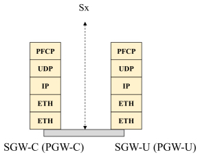
Figure 1.10. Protocol architecture of the Sx interface: the control plane
The CP and UP functions can evolve independently and implement the SDN (Software-Defined Networking) features providing centralized control and virtualization of functions.
A CP function can interface with several UP functions and a UP function can be controlled by several CP functions.
A mobile is served by a single SGW-C entity but several SGW-U entities can be selected for different PDN connections.
The CP function controls the processing of packets in the UP function by providing a set of rules in the Sx sessions:
- – the rules relating to the packet detection rules for packet inspection;
- – the rules relating to the transfer of packets;
- – the rules relating to the control of the quality of service;
- – the rules relating to the measurement of the traffic.
The S5-C interface is the reference point between the SGW-C and PGW-C entities. This interface supports GTPv2-C signaling.
The S5-U interface is the reference point between the SGW-U and PGW-U entities. This interface supports GTP-U tunneling of the IP packet of the stream.
The main features of the PFCP protocol are:
- – an Sx association must be established between a CP function and a UP function before Sx sessions can be established on the UP function. The Sx association can be established by the CP function or by the UP function;
- – an Sx session is established in the UP function to provide rules indicating the UP function how to handle certain traffic. An Sx session may correspond to a connection to the PDN or to a standalone session.
The procedures for the Sx association include the following:
- – the establishment, modification and release of the Sx association;
- – the checking that the remote PFCP application is active;
- – the control to balance the load between the UP functions.
The procedures for the Sx session include the following:
- – the establishment, modification and release of the Sx session;
- – the Sx session report to signal specific events, for example reception of data, when the mobile is in the idle state.
Data transfer between the CP and UP functions is supported by GTP-U tunneling in order to transmit user plane data to the SGW-C (see network optimization described in section 10.2).
1.3. Heterogeneous networks
The E-UTRAN is homogeneous when coverage is done from macro cells.
The coverage of macro cells can vary from a kilometer to a few tens of kilometers. The output power is of the order of tens of watts.
One way to extend a radio access network in order to increase the traffic flow capacity, while maintaining it as a homogeneous network, is to densify it by adding more sectors per eNB entity or to decrease the size of the macro cell to constitute micro cells.
Micro cells usually cover smaller areas of up to one kilometer. They typically transmit in a power range of a few milliwatts to a few watts.
However, the reduction in the size of the cell has limits because finding new sites becomes increasingly difficult and expensive, especially in the city centers.
An alternative to extending a radio access network deployed from macro cells is to introduce small cells by adding existing low-power radio stations or remote radio heads to existing macro cells. The acquisition of the site is easier and less expensive with this type of equipment.
The HeNB (Home eNB) radio station is used to build femto cells and to provide additional coverage inside buildings.
The relay node (RN) is another type of low-power radio station. The relay node is connected to a DeNB (Donor eNB) radio station via an LTE-Uu-type radio interface. From the perspective of the mobile, the relay node acts as an eNB entity. From the perspective of the DeNB entity, the relay node acts as a mobile.
The remote radio head (RRH), connected to an eNB entity via an optical fiber, can also be used to provide a small cell coverage, the assembly constituting a distributed radio station.
Dual connectivity (DC) allows simultaneous connections on a macro cell and a small cell to improve traffic flow capacity. The aggregation of the radio resources of the two cell types is performed by the eNB entity of the macro cell.
1.3.1. HeNB station
The first architecture variant of the E-UTRAN implementing the HeNB entity is described in Figure 1.11.
This variant is similar to the initial architecture:
- – the HeNb and MME entities are the terminations of the S1-MME interface;
- – the HeNB and SGW entities are the terminations of the S1-U interface.

Figure 1.11. Functional architecture implementing the HeNB station: variant 1
This variant has the following drawbacks:
- – an SCTP (Stream Control Transmission Protocol) association is set up between each HeNB entity and the MME entity. The messages of the presence control of the association ends (heartbeat) can create an overhead on the MME entity;
- – the user can turn the HeNB entity on and off. Frequent establishment and release messages from the SCTP association may also create an overhead on the MME entity;
- – a GTP-U tunnel is connected between each HeNB entity and the SGW entity. The control messages associated with the GTP-U tunnel (Path, Echo) can also create an overhead at the SGW entity.
The second architecture variant of the E-UTRAN implementing the HeNB entity is described in Figure 1.12. This variant introduces a new HeNB GW (Gateway) entity between, on the one hand, the HeNB entity and, on the other hand, the MME and SGW entities.
The HeNB GW entity concentrates the SCTP associations with each HeNB entity and creates a single SCTP association with the MME entity. This arrangement makes it possible to reduce the load of the MME entity.
The HeNB GW entity makes a connection between the media created, on the one hand, between each HeNB entity and the HeNB GW entity and, on the other hand, between the HeNB entity and the SGW entity. This arrangement makes it possible to limit, at the SGW entity level, the number of control messages associated with the GTP-U tunnel.

Figure 1.12. Functional architecture implementing the HeNB station: variant 2
The third architecture variant of the E-UTRAN implementing the HeNB entity is described in Figure 1.13. This variant introduces the HeNB GW entity only between each HeNB entity and the MME entity, which limits the load only for the MME entity.

Figure 1.13. Functional architecture implementing the HeNB station: variant 3
The HeNB entity can operate in one of the following three different access modes:
- – closed access: the HeNB entity is associated with a closed subscriber group (CSG) whose access is allowed. Closed access is applicable to residential deployment;
- – open access: the HeNB entity is open to all of the operator’s customers. Open access is applicable to deployment in high traffic areas, such as railway stations and airports;
- – hybrid access: as for closed access, the HeNB entity is reserved for a group of users, but it is also accessible to the operator’s customers, with a lower priority level.
In order to limit the number of SCTP associations that the HeNB entity has to establish with its neighbors on the X2 interface, an X2-GW concentrator can be integrated into the HeNB GW entity. A single SCTP association is established between the X2-GW concentrator and each HeNB entity.
Table 1.1 summarizes the handover possibilities between the HeNB and eNB entities depending on the type of access.
Table 1.1. Different types of X2-based handover
| Source | Target |
| eNB or HeNB (any type of access) | HeNB with open access |
| eNB or HeNB (any type of access) | HeNB with hybrid access |
| HeNB with hybrid or closed access | HeNB with closed access (1) |
| HeNB (any type of access) | eNB |
(1) Only for a closed subscriber group.
1.3.2. Relay node
The architecture of the E-UTRAN implementing the relay node (RN) is described in Figure 1.14.

Figure 1.14. Functional architecture implementing the relay node
The frequency bands used by the relay node may be different for the LTE-Uu and Un interfaces or the same if the coverage areas of the RN and DeNB entities are disjoint.
A time division of the frame between the LTE-Uu and Un interfaces is necessary to use the same frequency band for these two interfaces while having a coverage area common to both RN and DeNB entities.
Since the relay node (RN) is considered as a mobile by the DeNB entity, it exchanges NAS messages with the MME entity, carried by the following protocols (Figure 1.15):
- – RRC, exchanged between the relay node and the DeNB entity, via the Un interface;
- – S1-AP, exchanged between the DeNB and MME entities, via the S1-MME interface.

Figure 1.15. Connecting the relay node: the control plane
The DeNB entity acts as a proxy for S1-AP messages exchanged between the relay node and the MME entity (Figure 1.16) and for X2-AP messages exchanged between the relay node (respectively source or target) and the eNB entity (respectively target or source).
NAS messages exchanged between the mobile and the MME entity are carried by the following messages (Figure 1.16):
- – RRC, exchanged between the mobile and the relay node, via the LTE-Uu interface;
- – S1-AP, exchanged between the relay node and the DeNB entity, via the S1-MME interface;
- – S1-AP, exchanged between the DeNB and MME entities, via the S1-MME interface.

Figure 1.16. Connecting the mobile: the control plane
The mobile stream (IP packet) is transmitted in bearers to the SGW entity (Figure 1.17):
- – the data radio bearer (DRB), on the LTE-Uu interface;
- – the GTP-U tunnel, built between the relay node and the DeNB entity, on the S1-U interface;
- – the GTP-U tunnel, built between the DeNB and SGW entities, on the S1-U interface.

Figure 1.17. Connecting the mobile: the user plane
The DeNB entity provides the connection of established bearers, on the one hand, between the relay node and the DeNB entity and, on the other hand, between the DeNB and SGW entities.
The X2 interface is the reference point, on the one hand, between the eNB and DeNB entities and, on the other hand, between the DeNB entity and the relay node.
The X2 interface supports X2-AP signaling for the control plane (Figure 1.18), and GTP-U tunneling for the IP packet of the flow, when the mobile changes cell during the session (Figure 1.19).

Figure 1.18. Protocol architecture of the X2 interface: the control plane

Figure 1.19. Protocol architecture of the X2 interface: the user plane
The DeNB entity provides unidirectional tunnels for the following media: source eNB entity to target RN entity or source RN to target eNB.
These tunnels transfer the user data received from the SGW entity to the target eNB entity or the target RN entity. It is temporarily established during the handover of the mobile.
1.3.3. RRH module
The eNB entity consists of two modules: the base band unit (BBU) providing the various processing and the radio transmitters/receivers. The remote radio head (RRH) is obtained from a removal of the transmitters/receivers via an optical fiber (Figure 1.20).
C-RAN (Cloud Radio Access Network) makes it possible to benefit from decentralized radio equipment that is simpler, easier and less expensive to maintain. In addition, the centralization and the virtualization of the BBU module make it possible to share its use for several cells.
The common public radio interface (CPRI) defines the communication between the BBU and RRH modules.

Figure 1.20. C-RAN architecture
Tables 1.2 and 1.3 provide the characteristics of the CPRI rate in the case of a 20 MHz radio channel for one antenna.
Table 1.2. CPRI payload rate
| Sampling frequency | 30.72 MHz |
| Number of bits per sample | 30 |
| CPRI payload rate | 921.6 Mbps |
Table 1.3. CPRI rate
| Number of bits for the CPRI payload | 240 |
| Number of bits for the CPRI header | 16 |
| CPRI payload rate | 921.6 Mbps |
| CPRI frame rate | 983 Mbps |
| CPRI rate (8B/10B) | 1.2288 Gbps |
All operations above the physical layer and most of those in the physical layer are performed by the BBU module, which generates the radio signal, samples it and sends the resulting data to the RRH module.
The RRH module reconstructs the waveform and transmits it over the radio interface. The case of the uplink is similar, although the sampling of the radio signal must be done in the RRH module.
Figure 1.21 shows the functional distribution between the BBU and RRH modules for the downstream direction.

Figure 1.21. Distribution of functions between the BBU and RRH modules
The basic CPRI module (option 1) has a data rate of 614.4 Mbps. A 20 MHz radio channel uses two basic CPRI modules (option 2). A 20 MHz radio channel using the 2 × 2 MIMO (Multiple Input Multiple Output) transmission mode consumes four basic CPRI modules (option 3), a bit rate of 2.4576 Gbps.
The number of radio channels carried on the CPRI for an antenna depends on the rate of the radio interface and the bandwidth of the radio channel (Table 1.4).
Table 1.4. Number of radio channels carried on the CPRI
| CPRI rate (option)(Mbps) | Coding | Radio channel bandwidth | |||
| 10 MHz | 15 MHz | 20 MHz | |||
| Radio channel rate (Mbps) | |||||
| 614.4 | 92116 | 1228.8 | |||
| Option 1 | 614.4 | 8B/10B | 1 | 0 | 0 |
| Option 2 | 1228.8 | 8B/10B | 2 | 1 | 1 |
| Option 3 | 2457.6 | 8B/10B | 4 | 2 | 2 |
| Option 4 | 3072 | 8B/10B | 5 | 3 | 2 |
| Option 5 | 4915.2 | 8B/10B | 8 | 5 | 4 |
| Option 6 | 6144 | 8B/10B | 10 | 6 | 5 |
| Option 7 | 9830.4 | 8B/10B | 16 | 10 | 8 |
| Option 8 | 10137.6 | 64B/66B | 20 | 13 | 10 |
| Option 9 | 12165.12 | 64B/66B | 24 | 16 | 12 |
1.3.4. Dual connectivity
Dual connectivity (DC) is a mechanism for sharing the transmission of IP packets between two radio stations: the master eNB station (MeNB), which covers a macro cell, and the secondary eNB station (SeNB), which usually covers a small cell (Figure 1.22).

Figure 1.22. Functional architecture implementing dual connectivity
1.3.4.1. User plane
Two types of architecture are defined for the user plane (Figure 1.23):
- – for the 3C architecture, the GTP-U tunnels of the S1-U interface, corresponding to the master cell group (MCG), terminate at the MeNB entity and some bearers (split bearers) are transferred from the MeNB entity to the SeNB entity, in GTP-U tunnels, on the X2 interface, at the PDCP layer;
- – for the 1A architecture, the GTP-U tunnels of the S1-U interface, corresponding to the MCG, terminate at the MeNB entity, and those corresponding to the SCG at the SeNB entity level.

Figure 1.23. Protocol architecture of the radio interface implementing dual connectivity
1.3.4.2. Control plane
RRC messages are exchanged only between the mobile and the MeNB entity, on the LTE-Uu interface.
S1-AP messages are exchanged only between the MeNB and MME entities, on the S1-MME interface.
NAS messages exchanged between the mobile and the MME entity are carried by the RRC messages on the LTE-Uu interface and the S1-AP messages on the S1-MME interface.
X2-AP messages exchanged between the MeNB and SeNB entities must be enriched to account for dual connectivity:
- – creating, modifying and terminating the context at the SeNB entity level;
- – the transmission of the PDCP frame on the X2 interface and the management of the sequence numbers of the frame (3C architecture);
- – the handover management, taking into account the change of SeNB entities, while maintaining the MeNB entity, the downstream data to be transferred from the source SeNB entity to the MeNB entity (1A architecture);
- – the handover management, taking into account the change of MeNB entities, the downstream data to be transferred from the SeNB entity to the source MeNB entity (1A and 3C architectures).