
An illustration of the Joker robot standing back at the square object. The Square object has circular light in front of its surface.
The Color Sensor
Exercise: The Brightness Beeper

An illustration of the rectangular object with multiple holes in rows and columns. The sensor, hub, 4 horizontal T-shaped stacked blocks, and a robot are on a rectangular plane object. The hub and sensor connect with a wire, and the sensor is in front of the T blocks.
The Brightness Beeper plays a tone that varies with brightness of light
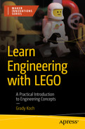
Building the Brightness Beeper

A 3D model and illustration of a rectangular panel with several cavities in columns and rows. The illustration exhibits 2 pins connected on the top face and 4 pins on the side

An illustration of a hub in a rectangular box. The hub is near the rectangular panel, which has several cavities in columns and rows. It exhibits 2 pins connected on the top face of the rectangular panel.

An illustration of the zoomed view of the sensor which is in a square shape with a wire. The sensor is on the rectangular panel and connects with a hub.

An illustration displays how an object is formed by connecting three T-shaped lift arms side by side and placed in front of the sensor.

An illustration displays the display screen of the hub. The sensor connects to the B port of the Hub and exhibits 75% at the bottom.
The Hub status screen will show a measurement when the Color Sensor is connected
Programming the Brightness Beeper
While the level of light measured by the Color Sensor can be viewed in the Robot Inventor app, such as in Figure 9-3, this data can also be put to use. As an example, the light level can be made proportional to the pitch of a tone. When the light level changes, by moving the reflector liftarm stack, the pitch will change. Coding examples can be found as follows.
The Word Blocks Code

A screenshot of the code screen depicts the 4 steps, such as start, repeat, beep, and stop, and other options of the starts program and exit program.
Word Blocks code for the Brightness Beeper
Step 3: The play beep block produces a sound on the Hub’s speaker. The Color Sensor’s reading, represented as a percentage, is converted into the MIDI note to play. A higher MIDI value corresponds to a higher pitch, so the beep will get higher when more light is reflected into the Color Sensor. The default duration setting of 0.2 seconds is a good choice to produce a quick beep that will rapidly update as the loop restarts.
The Python Code
An object is needed to represent the Color Sensor, given the variable name color in this case 1. A function associated with color is get_reflected_light(), used to measure the brightness of the light reflected from the sensor’s built-in light source. The measurement result from this function is assigned to a variable named brightness 2. However, this brightness value will be between 0 and 100 percent, which won’t work well to represent a musical MIDI note, as these notes range from 43 to 123. So a mathematical manipulation converts the possible brightness values to corresponding values within the desired MIDI range. This new value is assigned to a variable named note 3. The speaker.beep() function plays this note for a duration of 0.2 seconds 4. After the note is played, the loop runs through again to play another note.
A good start on using the Brightness Beeper is to place the stack of liftarms a couple centimeters away from the Color Sensor. A beep should result that quickly repeats. Moving the liftarm stack closer or farther away will make the beep change in pitch. But if the stack is placed very close, such that the stack almost touches the Color Sensor, the tone goes to a low pitch. This low pitch indicates that not much light is being reflected into the Color Sensor, which happens because the direction of the reflected light is not well aligned to hit the light-sensitive part of the Color Sensor.
Project: The Color Sorter

An illustration of the rectangular panel with a sensor, robot, 3 holes long lift arms with different colors, and other materials on it.
The Color Sorter places liftarms of a selected color into one side of a basket
Building the Color Sorter
The Color Sorter has four separate components to build: the baseplate, the chute, the pusher, and the basket. Building instructions for each of these four components are l presented as follows. The final assembly step then combines the chute, pusher, and basket onto the baseplate.
The Baseplate

A 3-D model and an illustration of a rectangular panel with several cavities in multiple rows and columns and has 3 different shaped and sized pins.

An illustration display how three 5-hole long straight liftarms and one 5-hole long ll-shaped liftarm are connected on a panel plate to build a color sorter.

An illustration of the rectangular panel plate with several holes in multiple rows and columns. Some pins are inside the holes, and 2 pins are at the side of a panel.

An illustration displays how a rectangular frame connects with the help of two pins at the side of a panel plate to build a color sorter.

An illustration displays how two pins are connected at the corners of the rectangular frame connected with a panel plate to build a color sorter.

An illustration displays how two 11-hole long straight lift arms on the side of a rectangular frame connected with a panel plate to build a color sorter.

An illustration displays how two pins are connected at the side of a panel plate to build a color sorter.

an illustration displays how two 15-hole long straight lift arms are connected at the bottom of a panel plate to build a color sorter.

An illustration displays how three pins are connected at the side of a panel plate to build a color sorter.

An illustration displays how a motor connects with the help of three pins at the left side of a panel plate to build a color sorter.
An illustration displays how two pins are connected at the longer side of a panel plate to build a color sorter. A motor is on the left side of the panel, and the rectangular with vertical lift arms are on the right side.

An illustration displays how a hub connects with the help of two pins at the longer side of a panel plate to build a color sorter. A motor is on the left side of the panel, the hub is at the top, and the rectangular with vertical lift arms are on the right side.
The Chute

An illustration displays how four fins are connected at the flattened surface of the lego 3 by 11 technic panel to build a chute for the color sorter.

An illustration displays how two 15-hole long straight liftarms are connected at the flattened surface of the lego technic panel to build a chute for the color sorter.

An illustration displays how two lego technic panels are connected on both sides of two 15-hole long straight liftarms to build a chute for the color sorter.

An illustration displays how two 13-hole long straight liftarms are connected with technic panels to build a chute for the color sorter.

An illustration displays how two 13-hole long straight liftarms are connected to the technic panels to build a chute for the color sorter.

An illustration displays how two pins connect on 13-hole long straight liftarms to build a chute for the color sorter.

An illustration displays how a three-pin straight liftarm connects to 13-hole long straight liftarms to build a chute for the color sorter.

An illustration displays how four pins connect on two 15-hole long straight liftarms to build a chute for the color sorter.

An illustration displays how a sensor connects on two 15-hole long straight lift arms to build a chute for the color sorter.

An illustration displays how four pins connect to the sensor and a 3 by 3 technic panel to build a chute for the color sorter.

An illustration displays how two 15-hole long straight liftarms connect on the sensor and a 3 by 3 technic panel to build a chute for the color sorter.

An illustration displays how two 3-hole long straight liftarm connects on the 15-hole long straight liftarms to build a chute for the color sorter.

An illustration displays how two 4 pins connect at the endpoint of four 15-hole long straight liftarms to build a chute for the color sorter.

An illustration displays how two 3 by 3 technic panels connect at the endpoint of four 15-hole long straight liftarms to build a chute for the color sorter.
The Pusher

An illustration displays how a pin is connected to the side of the motor to build a pusher for the color sorter.

An illustration displays how a 13-hole long straight liftarm connects to the motor to build a pusher for the color sorter.

An illustration displays how two pins and an axle connect to13-hole long straight liftarm to build a pusher for the color sorter.

An illustration displays how a 3-hole long straight liftarm connects to13-hole long straight liftarm to build a pusher for the color sorter.

An illustration displays how a 5-hole long straight liftarm connects to13-hole long straight liftarm to build a pusher for the color sorter.

An illustration displays how a long axle connects beside the 13-hole long straight liftarm to build a pusher for the color sorter.

An illustration displays how three rectangular frames connect to build a platform of a pusher for the color sorter.

An illustration displays how three rectangular frames are connected to build a platform of a pusher for the color sorter.

An illustration displays how eight pins and three rectangular frames interconnect to build a platform of a pusher for the color sorter.
 An illustration displays how a pusher connects to a platform of rectangular frames to build a color sorter.
The Basket
The basket holds the sorted liftarms, with the selected color on one side and other colors on the opposite side. A motor spins the basket to change the side of the basket in which the liftarms are dropped. The two halves of the basket are separated by a wall.

An illustration displays how a pin connects with a 7-hole long liftarm to build a basket for the color sorter. 2 pins are at both ends.

An illustration displays how two 9-hole long liftarms connect on both sides of a 7-hole long liftarm in an I-shape, to build a basket for the color sorter.

An illustration displays how eight pins connect with an I-shaped structure to build a basket for the color sorter.

An illustration displays how four L-shaped liftarms are connected with an I-shaped structure to build a basket for the color sorter.

An illustration displays how 10 pins are connected on four L-shaped liftarms to build a basket for the color sorter.

An illustration displays how two 7-hole long and one 5-hole lone liftarms connect with the structure to build a basket for the color sorter.

An illustration displays how 14 pins connect with the structure to build a basket for the color sorter.

An illustration displays how six 5-hole long and one 7-hole lone liftarms connect with the structure to build a basket for the color sorter.

An illustration displays how three 3 by 3 technic panels connect side by side with the help of four pins to build the basket for the color sorter.

An illustration displays how two 3-hole long straight liftarms connect on both sides of a 3 by 3 technic panel to build the basket for the color sorter.

An illustration displays how two 3-hole long straight liftarms and three 3 by 3 technic panels are interconnected to build the basket for the color sorter.

An illustration displays how two pins connect at the 3 by 3 technic panels to build the basket for the color sorter.

An illustration displays how the structure of 3 by 3 technic panels connects at the bottom of the structure formed earlier to build the basket for the color sorter.

An illustration displays how eight pins connect at the bottom of the structure to build the basket for the color sorter.

An illustration displays how two 11-hole long liftarms connect at the bottom of the structure to build the basket for the color sorter.
Final Assembly

An illustration displays the locations on the panel plate where the basket, chute, and pusher are to be mounted.
Map of placement of the basket, chute, and pusher on the baseplate

An illustration displays how to mount the basket on the panel plate to build the color sorter.

An illustration displays how to mount the chute on the panel plate to build the color sorter.

An illustration displays how to mount the pusher on the panel plate to build the color sorter.

An illustration displays the model of the color sorter built with a robot inventory set. The basket motor cable has to connect with port A, the sensor cable to port C, and the pusher motor cable to port E of the hub.
Programming the Color Sorter
Load a liftarm onto the Color Sensor by moving the pusher motor. Wait for one second to allow the Color Sensor to take a measurement. If the measured color is the one preselected (red in this example), set the basket motor’s angle position to one side of the basket. For all other colors, orient the basket motor to the other side of the basket. Push the liftarm into the basket by moving the pusher motor. Repeat these steps for all six liftarms loaded into the chute.
- 1.
Start the program.
- 2.
Set the basket motor speed to 25 percent.
- 3.
Set the pusher motor speed to 100 percent.
- 4.
Create a loop that repeats six times.
- 5.
Move the pusher motor clockwise to the 180-degree position.
- 6.
Delay for one second.
- 7.
Determine whether the liftarm color is red. If yes, go to step 8. If no, go to step 9.
- 8.
Move the basket motor to the 180-degree position.
- 9.
Move the basket motor to the zero-degree position.
- 10.
Move the pusher motor counterclockwise to the zero-degree position.
- 11.
Stop the program.

A flowchart presents the algorithm for the color sorter. Step 4 has a loop from step 10 that repeats six times. An if conditional is embedded within the loop to decide the orientation of the basket.
Flowchart of the Color Sorter algorithm
The Word Blocks Code

A screenshot of the code screen presents the word codes for the color sorter. A message box is associated with each word code.
Word Blocks code for the Color Sorter algorithm
Step 2: The set speed to block assigns the speed of the basket motor. Without this block, a motor will assume a default speed of 75 percent, which could cause jerky motions for the basket. A slower speed will move the basket smoothly.
Step 3: Another set speed to block assigns the pusher motor’s speed. Here, the maximum speed is desired to give the liftarms a firm shove into the basket.
Step 4: The repeat block sets up a loop that repeats six times, then stops. Loops have been used throughout the programs of this book that run indefinitely, but this loop only runs through a specified number of repetitions. Six repetitions are used here, because the Color Sorter holds six liftarms to be sorted.
Step 5: The go to position block sets the pusher motor’s angle to the position specified. This motion retracts the axle connected to the eccentric so that a liftarm drops from the chute onto the Color Sensor.
Step 7: The if then else block presents a condition—it checks if the liftarm seen by the Color Sensor is red. If the red condition is met, then the blocks within the first set of yellow bars will run. Otherwise, the blocks of the else section within the second yellow bars will run.
Step 8: The go to position block sets the basket motor’s angle to the position specified to collect liftarms that correspond to the selected color, red in this case. The basket has two halves, with one dedicated to the selected color and the other half for all other colors.
Step 9: Another go to position block sets the basket motor’s angle to the position specified to collect liftarms that are not the selected color. In other words, any liftarm that is not red will go into the side of the basket that corresponds to this motor position.
Step 10: The next go to position block works with the pusher motor, as opposed to the basket motor of the prior two blocks. This action on the pusher motor shoves the liftarm into the basket.
The Python Code
There are three objects to name in the program: the basket motor given the variable name basket 1, the Color Sensor given the variable name color 2, and the pusher motor given the variable name pusher 3. Loops commonly used in this book kept running indefinitely, but here a loop is set up that only runs six times, using a for loop 4. Six repetitions are used here because the Color Sorter holds six liftarms at the beginning of the program. The sorting routine, described as follows, thus gets run six times.
A set of statements runs inside the repeated loop. These load a liftarm onto the Color Sensor, take a color measurement, and decide to which side of the basket the liftarm should go. To load a liftarm, the pusher is retracted with the run_to_position() function 5. After a pause, the Color Sensor measures the liftarm’s color and assigns the result to a variable named measurement 6. An if conditional selects one of two options depending on the detected color. If measurement matches the value of red, the basket motor goes to a position of 180 degrees using the run_to_position() function 7. The second option, in the else block, occurs if the measurement isn’t red. It presents the other half of the basket. After the basket has been positioned, a motor function shoves the liftarm into the basket.

A set of two liftarms. 1. a liftarm with 3 holes has a tick mark at the top. 2. a liftarm with no holes at the top has a cross mark at the top.
Liftarms should have holes facing the operator for loading into the chute
Summary
This chapter explored the use of the Color Sensor, which can measure the color of an object placed in front of the sensor. In addition to measuring color, the Color Sensor can also detect the brightness of light reflected back into the sensor from a light source built into the sensor. Color Sensor data can be viewed in the Robot Inventor app to give a quick look at measurements. An exercise built a device that beeps a tone on the Hub, with the tone changing depending on the brightness of light reflected back into the sensor. Then a more complex machine was built using color detection that sorts liftarms by their color. This project also involved motors that moved liftarms through the machine to sort them. The program for the Color Sorter involved the use of a loop that runs through a specified number of iterations, rather than running indefinitely.