
Chapter 15: Digging into the IIO Framework
Industrial input/output (IIO) is a kernel subsystem dedicated to analog-to-digital converters (ADCs) and digital-to-analog converters (DACs). With the growing numbers of sensors (measurement devices with analog-to-digital or digital-to-analog capabilities) with different code implementations, scattered across kernel sources, gathering them became necessary. That is what the IIO framework does, in a generic way. Jonathan Cameron and the Linux IIO community have been developing it since 2009. Accelerometers, gyroscopes, current/voltage measurement chips, light sensors, and pressure sensors all fall into the IIO family of devices.
The IIO model is based on device and channel architecture:
- The device represents the chip itself, the top level of the hierarchy.
- The channel represents a single acquisition line of the device. A device may have one or more channels. For example, an accelerometer is a device with three channels, one for each axis (x, y, and z).
The IIO chip is the physical and hardware sensor/converter. It is exposed to the user space as a character device (when a triggered buffer is supported) and a sysfs directory entry that will contain a set of files, some of which represent the channels.
These are the two ways to interact with an IIO device from user space:
- /sys/bus/iio/iio:deviceX/, a sysfs directory that represents the device along with its channels
- /dev/iio:deviceX, a character device that exports the device's events and data buffer
As a picture is worth a thousand words, the following is a figure showing an overview of the IIO framework:

Figure 15.1 – IIO framework overview
The preceding figure shows how the IIO framework is organized between the kernel and the user space. The driver manages the hardware and reports processing to the IIO core, using a set of facilities and APIs exposed by the IIO core. The IIO subsystem then abstracts the whole underlying mechanism to user space by means of the sysfs interface and the character device, on top of which users can execute system calls.
IIO APIs are spread over several header files, as follows:
/* mandatory, the core */
#include <linux/iio/iio.h>
/* mandatory since sysfs is used */
#include <linux/iio/sysfs.h>
/* Optional. Advanced feature, to manage iio events */
#include <linux/iio/events.h>
/* mandatory for triggered buffers */
#include <linux/iio/buffer.h>
/* rarely used. Only if the driver implements a trigger */
#include <linux/iio/trigger.h>
In this chapter, we will describe and handle every concept of the IIO framework, such as walking through its data structure (devices, channels, and so on), dealing with triggered buffer support and continuous capture, along with its sysfs interface, exploring existing IIO triggers, learning how to capture data in either one-shot mode or continuous mode, and listing tools that can help the developer in testing their devices.
In other words, we will cover the following topics in this chapter:
- Introduction to IIO data structures
- Integrating IIO triggered buffer support
- Accessing IIO data
- Dealing with the in-kernel IIO consumer interface
- Walking through user-space IIO tools
Introduction to IIO data structures
The IIO framework is made of a few data structures among which is one representing the IIO device, another one describing this device, and the last one enumerating the channels exposed by the device. An IIO device is represented in the kernel as an instance of struct iio_dev and described by a struct iio_info structure. All the important IIO structures are defined in include/linux/iio/iio.h.
Understanding the struct iio_dev structure
The struct iio_dev structure represents the IIO device, describing the device and its driver. It tells us how many channels are available on the device and what modes the device can operate in (one-shot or triggered buffer, for example). Moreover, this data structure exposes some hooks to be provided by the driver.
This data structure has the following definition:
struct iio_dev {
[...]
int modes;
int currentmode;
struct device dev;
struct iio_buffer *buffer;
int scan_bytes;
const unsigned long *available_scan_masks;
const unsigned long *active_scan_mask;
bool scan_timestamp;
struct iio_trigger *trig;
struct iio_poll_func *pollfunc;
struct iio_chan_spec const *channels;
int num_channels;
const char *name;
const struct iio_info *info;
const struct iio_buffer_setup_ops *setup_ops;
struct cdev chrdev;
};
For the sake of readability, only relevant elements for us have been listed in the preceding excerpt. The complete structure definition lies in include/linux/iio/iio.h. The following are the meanings of the elements in the data structure:
- modes represents the different modes supported by the device. Possible modes are as follows:
- INDIO_DIRECT_MODE: This says the device provides sysfs-type interfaces.
- INDIO_BUFFER_TRIGGERED: This says that the device supports hardware triggers associated with a buffer. This flag mode is automatically set when you set up a triggered buffer using the iio_triggered_buffer_setup() function.
- INDIO_BUFFER_SOFTWARE: In continuous conversions, the buffering will be implemented in software, by the kernel itself. The kernel will push data into the internal FIFO with a possible interrupt at a specified watermark.
- INDIO_BUFFER_HARDWARE: This means the device has a hardware buffer. In continuous conversions, the buffering can be handled by the device. This means that the data stream can be obtained directly from the hardware backend.
- INDIO_ALL_BUFFER_MODES: A union of the preceding three.
- INDIO_EVENT_TRIGGERED: Conversion can be triggered by some sort of event, such as a threshold voltage reached on an ADC, but no interrupt or timer trigger. This flag is intended to be used for comparator-equipped chips with no other way to trigger conversion.
- INDIO_HARDWARE_TRIGGERED: Can be triggered by hardware events, such as IRQ or clock events.
- INDIO_ALL_TRIGGERED_MODES union of INDIO_BUFFER_TRIGGERED, INDIO_EVENT_TRIGGERED, and INDIO_HARDWARE_TRIGGERED.
- currentmode: This represents the mode used by the device.
- dev: This represents the struct device (according to Linux Device Model) the IIO device is tied to.
- buffer: This is your data buffer, pushed to the user space when using triggered buffer mode. It is automatically allocated and associated with your device when you enable triggered buffer support using the iio_triggered_buffer_setup function.
- scan_bytes: This is the number of bytes captured to be fed to the buffer. When using a trigger buffer from the user space, the buffer should be at least indio->scan_bytes bytes large.
- available_scan_masks: This is an optional array of allowed bitmasks. When using a triggered buffer, you can enable channels to be captured and fed into the IIO buffer. If you do not want to allow some channels to be enabled, you should fill this array with only allowed ones. An example of an accelerometer (with X, Y, and Z channels) is as follows:
/*
* Bitmasks 0x7 (0b111) and 0 (0b000) are allowed.
* It means one can enable none or all of them.
* You can't for example enable only channel X and Y
*/
static const unsigned long my_scan_masks[] = {0x7, 0};
indio_dev->available_scan_masks = my_scan_masks;
- active_scan_mask: This is a bitmask of enabled channels. Only the data from those channels should be pushed into the buffer. For example, for an eight-channel ADC converter, if you only enable the first (index 0), the third (index 2), and the last (index 7) channels, the bitmask would be 0b10000101 (0x85). active_scan_mask will be set to 0x85. The driver can then use the for_each_set_bit macro to walk through each set bit, fetch the data from the corresponding channels, and fill the buffer.
- scan_timestamp: This tells whether to push the capture timestamp into the buffer or not. If true, the timestamp will be pushed as the last element of the buffer. The timestamp is 8 bytes (64 bits) large.
- trig: This is the current device trigger (when buffer mode is supported).
- pollfunc: This is the function run on the trigger being received.
- channels: This represents the table channel specification structure, to describe every channel the device has.
- num_channels: This represents the number of channels specified in channels.
- name: This represents the device name.
- info: Callbacks and constant information from the driver.
- setup_ops: A set of callback functions to call before and after the buffer is enabled/disabled. This structure is defined in include/linux/iio/iio.h, as follows:
struct iio_buffer_setup_ops {
int (* preenable) (struct iio_dev *);
int (* postenable) (struct iio_dev *);
int (* predisable) (struct iio_dev *);
int (* postdisable) (struct iio_dev *);
bool (* validate_scan_mask) (
struct iio_dev *indio_dev,
const unsigned long *scan_mask);
};
Note that each callback in this data structure is optional.
- chrdev: Associated character device created by the IIO core, with iio_buffer_fileops as the file operation table.
Now that we are familiar with the IIO device structure, the next step is to allocate memory for it. The appropriate function to achieve that is devm_iio_device_alloc(), which is the managed version for iio_device_alloc() and has the following definition:
struct iio_dev *devm_iio_device_alloc(struct device *dev,
int sizeof_priv)
It is recommended to use the managed version in a new driver as the devres core takes care of freeing the memory when it is no longer needed. In the preceding function prototype, dev is the device to allocate iio_dev for and sizeof_priv is the extra memory space to allocate for any private data structure. The function returns NULL if the allocation fails.
After the IIO device memory has been allocated, the next step is to initialize different fields. Once done, the device must be registered with the IIO subsystem using the devm_iio_device_register() function, the prototype of which is the following:
int devm_iio_device_register(struct device *dev,
struct iio_dev *indio_dev);
This function is the managed version of iio_device_register() and takes care of unregistering the IIO device on driver detach. In its parameters, dev is the same device as the one for which the IIO device has been allocated, and indio_dev is the IIO device previously initialized. The device will be ready to accept requests from the user space after this function succeeds (returns 0). The following is an example showing how to register an IIO device:
static int ad7476_probe(struct spi_device *spi)
{
struct ad7476_state *st;
struct iio_dev *indio_dev;
int ret;
indio_dev = devm_iio_device_alloc(&spi->dev,
sizeof(*st));
if (!indio_dev)
return -ENOMEM;
/* st is given the address of reserved memory for
* private data
*/
st = iio_priv(indio_dev);
[...]
/* iio device setup */
indio_dev->name = spi_get_device_id(spi)->name;
indio_dev->modes = INDIO_DIRECT_MODE;
indio_dev->num_channels = 2;
[...]
return devm_iio_device_register(&spi->dev, indio_dev);
}
If an error occurs, devm_iio_device_register() will return a negative error code. The reverse operation for the non-managed variant (usually done in the release function) is iio_device_unregister(), which has the following declaration:
void iio_device_unregister(struct iio_dev *indio_dev)
However, managed registration takes care of unregistering the device on driver detach or when the device leaves the system. Moreover, because we used a managed allocation variant, there is no need to free the memory as this will be internal to the core.
You might have also noticed we used a new function in the excerpt, iio_priv(). This accessor returns the address of the private data allocated with the IIO device. It is recommended to use this function instead of doing a direct dereference. As an example, given an IIO device, the corresponding private data can be retrieved as follows:
struct my_private_data *the_data = iio_priv(indio_dev);
The IIO device is useless on its own. Now that we are done with the main IIO device data structure, we have to add a set of hooks allowing us to interact with the device.
Understanding the struct iio_info structure
The struct iio_info structure is used to declare the hooks used by the IIO core to read/write channel/attribute values. The following is part of its declaration:
struct iio_info {
const struct attribute_group *attrs;
int (*read_raw)(struct iio_dev *indio_dev,
struct iio_chan_spec const *chan,
int *val, int *val2, long mask);
int (*write_raw)(struct iio_dev *indio_dev,
struct iio_chan_spec const *chan,
int val, int val2, long mask);
[...]
};
Again, the full definition of this data structure can be found in /include/linux/iio/iio.h. For the enumerated elements in the preceding structure excerpt, the following are their meanings:
- attrs represents the device attributes exposed to user space.
- read_raw is the callback invoked when a user reads a device sysfs file attribute. The mask parameter is a bitmask allowing us to know which type of value is requested. The chan parameter lets us know the channel concerned. *val and *val2 are output parameters that must contain the elements making up the returned value. They must be set with raw values read from the device.
The return value of this callback is kind of standardized and indicates how *val and *val2 must be handled by the IIO core to compute the real value. Possible return values are the following:
- IIO_VAL_INT: The output value is an integer. In this case, the driver must set *val only.
- IIO_VAL_INT_PLUS_MICRO: The output value is made of an integer part and a micro part. The driver must set *val with the integer value, while *val2 must be set with the micro value.
- IIO_VAL_INT_PLUS_NANO: This is the same as the micro, but *val2 must be set with the nano value.
- IIO_VAL_INT_PLUS_MICRO_DB: The output values are in dB. *val must be set with the integer part and *val2 must set with the micro part, if any.
- IIO_VAL_INT_MULTIPLE: val is considered as an array of integers and *val2 is the number of entries in the array. They must be set accordingly then. The maximum size of val is INDIO_MAX_RAW_ELEMENTS, defined as 4.
- IIO_VAL_FRACTIONAL: The final value is fractional. The driver must set *val with the numerator and *val2 with the denominator.
- IIO_VAL_FRACTIONAL_LOG2: The final value is a logarithmic fractional. The IIO core expects the denominator (*val2) to be specified as the log2 of the actual denominator. For example, for ADCs and DACs, this will usually be the number of significant bits. *val is a normal integer denominator.
- IIO_VAL_CHAR: The IIO core expects *val to be a character. This is, most of the time, used with the IIO_CHAN_INFO_THERMOCOUPLE_TYPE mask, in which case the driver must return the type of thermocouple.
All the preceding does not change the fact that, in case of an error, the callback must return a negative error code, for example, -EINVAL. I recommend you have a look at how the final value is processed in iio_convert_raw_to_processed_unlocked() in the drivers/iio/inkern.c source file.
- write_raw is the callback used to write a value to the device. You can use it, for example, to set the sampling frequency or change the scale.
An example of setting up the struct iio_info structure is the following:
static const struct iio_info iio_dummy_info = {
.read_raw = &iio_dummy_read_raw,
.write_raw = &iio_dummy_write_raw,
[...]
};
/*
* Provide device type specific interface functions and
* constant data.
*/
indio_dev->info = &iio_dummy_info;
You must not confuse this struct iio_info with the user-space iio_info tool, which is part of the libiio package.
The concept of IIO channels
In IIO terminology, a channel represents a single acquisition line of a sensor. This means each data mesurement entity a sensor can provide/sense is called a channel. For example, an accelerometer will have three channels (X, Y, and Z), since each axis represents a single acquisition line. struct iio_chan_spec is the structure that represents and describes a single channel in the kernel, as follows:
struct iio_chan_spec {
enum iio_chan_type type;
int channel;
int channel2;
unsigned long address;
int scan_index;
struct {
char sign;
u8 realbits;
u8 storagebits;
u8 shift;
u8 repeat;
enum iio_endian endianness;
} scan_type;
long info_mask_separate;
long info_mask_shared_by_type;
long info_mask_shared_by_dir;
long info_mask_shared_by_all;
const struct iio_event_spec *event_spec;
unsigned int num_event_specs;
const struct iio_chan_spec_ext_info *ext_info;
const char *extend_name;
const char *datasheet_name;
unsigned modified:1;
unsigned indexed:1;
unsigned output:1;
unsigned differential:1;
};
The following are the meanings of elements in the data structure:
- type specifies which type of measurement the channel makes. In the case of voltage measurement, it should be IIO_VOLTAGE. For a light sensor, it is IIO_LIGHT. For an accelerometer, IIO_ACCEL is used. All available types are defined in include/uapi/linux/iio/types.h, as enum iio_chan_type. To write a driver for a given converter, you have to look into that file to see the type each of your converter channels falls into.
- channel specifies the channel index when .indexed is set to 1.
- channel2 specifies the channel modifier when .modified is set to 1.
- The scan_index and scan_type fields are used to identify elements from a buffer, when using buffer triggers. scan_index sets the position of the captured channel inside the buffer. Channels are placed in the buffer ordered by scan_index, from the lowest index (placed first) to the highest index. Setting .scan_index to -1 will prevent the channel from buffered capture (no entry in the scan_elements directory). Elements in this substructure have the folowing meanings:
- sign: s or u specifies symbols (signed (complement of 2) or unsigned).
- realbits: The number of valid data bits.
- storagebits: The number of digits occupied by this channel in the buffer. That is to say, a value can really be encoded with 12 bits, but it occupies 16 bits (storage bits) in the buffer. Therefore, the data must be moved four times to the right to get the actual value. This parameter depends on the device and you should refer to its datasheet.
- shift: Represents the number of times data values should be right-shifted before masking out unused bits. This parameter is not always required. If the number of valid bits equals the number of storage bits, the shift will be 0. This parameter can also be found in the device datasheet.
- repeat: The number of times real/storage bits repeat.
- endianness: Represents the data endianness. It is of the enum iio_endian type and should be set with one of IIO_CPU, IIO_LE, or IIO_BE, which mean, the native CPU endianness, little endian, or big endian respectively.
- The modified field specifies whether a modifier is to be applied to this channel attribute name or not. In that case, the modifier is set in .channel2. (For example, IIO_MOD_X, IIO_MOD_Y, and IIO_MOD_Z are modifiers for axial-sensors about the X, Y, and Z axis). The available modifier list is defined in the kernel IIO header as enum iio_modifier. Modifiers only mangle the channel attribute name in sysfs, not the value.
- indexed specifies whether the channel attribute name has an index or not. If yes, the index is specified in the .channel field.
- info_mask_separate marks the attribute as being specific to this channel.
- info_mask_shared_by_type marks the attribute as being shared by all channels of the same type. The information exported is shared by all channels of the same type.
- info_mask_shared_by_dir marks the attribute as being shared by all channels of the same direction. The information exported is shared by all channels of the same direction.
- info_mask_shared_by_all marks the attribute as being shared by all channels, whatever their type or their direction may be. The information exported is shared by all channels.
iio_chan_spec.info_mask_* elements are masks used to specify channel sysfs attributes exposed to user space depending on their shared information. Therefore, masks must be set by ORing one or more bitmasks, all of which are defined in include/linux/iio/types.h, as follows:
enum iio_chan_info_enum {
IIO_CHAN_INFO_RAW = 0,
IIO_CHAN_INFO_PROCESSED,
IIO_CHAN_INFO_SCALE,
IIO_CHAN_INFO_OFFSET,
IIO_CHAN_INFO_CALIBSCALE,
[...]
IIO_CHAN_INFO_SAMP_FREQ,
IIO_CHAN_INFO_FREQUENCY,
IIO_CHAN_INFO_PHASE,
IIO_CHAN_INFO_HARDWAREGAIN,
IIO_CHAN_INFO_HYSTERESIS,
[...]
};
The following is an example of specifying a mask for a given channel:
iio_chan->info_mask_separate = BIT(IIO_CHAN_INFO_RAW) |
BIT(IIO_CHAN_INFO_PROCESSED);
This means raw and processed attributes are specific to the channel.
Note
While not specified in the preceding struct iio_chan_spec structure description, the term attribute refers to a sysfs attribute. This applies across the whole chapter.
Having described the channel data structure, let's decipher the mystery about channel attribute naming, which respects a specific convention.
Channel attribute naming convention
An attribute's name is automatically generated by the IIO core following a predefined pattern, {direction}_{type}{index}_{modifier}_{info_mask}. The following are descriptions of each field in the pattern:
- {direction} corresponds to the attribute direction, according to the struct iio_direction structure in drivers/iio/industrialio-core.c:
static const char * const iio_direction[] = {
[0] = "in",
[1] = "out",
};
Do note that an input channel is a channel that can generate samples (such channels are handled in the read method, for instance, an ADC channel). On the other hand, an output channel is a channel that can receive samples (such channels are handled in the write method, for instance, a DAC channel).
- {type} corresponds to the channel type string, according to the constant iio_chan_type_name_spec char array (indexed by the channel type of type enum iio_chan_type) defined in drivers/iio/industrialio-core.c, as follows:
static const char * const iio_chan_type_name_spec[] = {
[IIO_VOLTAGE] = "voltage",
[IIO_CURRENT] = "current",
[IIO_POWER] = "power",
[IIO_ACCEL] = "accel",
[...]
[IIO_UVINDEX] = "uvindex",
[IIO_ELECTRICALCONDUCTIVITY] =
"electricalconductivity",
[IIO_COUNT] = "count",
[IIO_INDEX] = "index",
[IIO_GRAVITY] = "gravity",
};
- {index} depends on the channel .indexed field being set or not. If set, the index will be taken from the .channel field in order to replace the {index} pattern.
- The {modifier} pattern depends on the channel .modified field being set or not. If set, the modifier will be taken from the .channel2 field, and the {modifier} field in the pattern will be replaced according to the char array struct iio_modifier_names structure:
static const char * const iio_modifier_names[] = {
[IIO_MOD_X] = "x",
[IIO_MOD_Y] = "y",
[IIO_MOD_Z] = "z",
[IIO_MOD_X_AND_Y] = "x&y",
[IIO_MOD_X_AND_Z] = "x&z",
[IIO_MOD_Y_AND_Z] = "y&z",
[...]
[IIO_MOD_CO2] = "co2",
[IIO_MOD_VOC] = "voc",
};
- {info_mask} depends on the channel info mask, private or shared, indexing the value in the iio_chan_info_postfix char array, defined as the following:
/* relies on pairs of these shared then separate */
static const char * const iio_chan_info_postfix[] = {
[IIO_CHAN_INFO_RAW] = "raw",
[IIO_CHAN_INFO_PROCESSED] = "input",
[IIO_CHAN_INFO_SCALE] = "scale",
[IIO_CHAN_INFO_CALIBBIAS] = "calibbias",
[...]
[IIO_CHAN_INFO_SAMP_FREQ] = "sampling_frequency",
[IIO_CHAN_INFO_FREQUENCY] = "frequency",
[...]
};
Channel naming convention should have no more secrets for us now. Now that we are familiar with the naming, let's learn how to precisely identify channels.
Note
In this naming pattern, if an element is not present, then the directly preceding underscore will be omitted. For example, if the modifier is not specified, the pattern becomes {direction}_{type}{index}_{info_mask} instead of {direction}_{type}{index}__{info_mask}.
Distinguishing channels
You may face some difficulties when there are multiple data channels of the same type. The dilemma would be how to precisely identify each of them. There are two solutions for that: indexes and modifiers.
Channel identification using an index
Given an ADC device with one channel line, indexing is not needed. Its channel definition would be as follows:
static const struct iio_chan_spec adc_channels[] = {
{
.type = IIO_VOLTAGE,
.info_mask_separate = BIT(IIO_CHAN_INFO_RAW),
},
}
Given the preceding excerpt, the attribute name will be in_voltage_raw, and its absolute sysfs path will be /sys/bus/iio/iio:deviceX/in_voltage_raw.
Now let's say the ADC has four or even eight channels. How do we identify each of them? The solution is to use indexes. Setting the .indexed field to 1 will modify the channel attribute name with the .channel value, replacing {index} in the naming pattern:
static const struct iio_chan_spec adc_channels[] = {
{
.type = IIO_VOLTAGE,
.indexed = 1,
.channel = 0,
.info_mask_separate = BIT(IIO_CHAN_INFO_RAW),
},
{
.type = IIO_VOLTAGE,
.indexed = 1,
.channel = 1,
.info_mask_separate = BIT(IIO_CHAN_INFO_RAW),
},
{
.type = IIO_VOLTAGE,
.indexed = 1,
.channel = 2,
.info_mask_separate = BIT(IIO_CHAN_INFO_RAW),
},
{
.type = IIO_VOLTAGE,
.indexed = 1,
.channel = 3,
.info_mask_separate = BIT(IIO_CHAN_INFO_RAW),
},
}
The following are the full sysfs paths of the resulting channel attributes:
/sys/bus/iio/iio:deviceX/in_voltage0_raw
/sys/bus/iio/iio:deviceX/in_voltage1_raw
/sys/bus/iio/iio:deviceX/in_voltage2_raw
/sys/bus/iio/iio:deviceX/in_voltage3_raw
As we can see, even if they all have the same type, they are differentiated by their index.
Channel identification using a modifier
To highlight the concept of modifiers, let's consider a light sensor with two channels – one for infrared light and the other for both infrared and visible light. Without an index or a modifier, an attribute name would be in_intensity_raw. Using indexes here can be error-prone because it makes no sense to have in_intensity0_ir_raw and in_intensity1_ir_raw as it would mean they are channels of the same type. Using a modifier will help us to have meaningful attribute names. The channel definition could look as follows:
static const struct iio_chan_spec mylight_channels[] = {
{
.type = IIO_INTENSITY,
.modified = 1,
.channel2 = IIO_MOD_LIGHT_IR,
.info_mask_separate = BIT(IIO_CHAN_INFO_RAW),
.info_mask_shared = BIT(IIO_CHAN_INFO_SAMP_FREQ),
},
{
.type = IIO_INTENSITY,
.modified = 1,
.channel2 = IIO_MOD_LIGHT_BOTH,
.info_mask_separate = BIT(IIO_CHAN_INFO_RAW),
.info_mask_shared = BIT(IIO_CHAN_INFO_SAMP_FREQ),
},
{
.type = IIO_LIGHT,
.info_mask_separate = BIT(IIO_CHAN_INFO_PROCESSED),
.info_mask_shared = BIT(IIO_CHAN_INFO_SAMP_FREQ),
},
}
The resulting attributes would be as follows:
- /sys/bus/iio/iio:deviceX/in_intensity_ir_raw for the channel measuring IR intensity
- /sys/bus/iio/iio:deviceX/in_intensity_both_raw for the channel measuring both
- /sys/bus/iio/iio:deviceX/in_illuminance_input for the processed data
- /sys/bus/iio/iio:deviceX/sampling_frequency for the sampling frequency, shared by all
This is valid with an accelerometer too, as we will see in a later case study. For now, let's summarize what we have discussed so far by implementing a dummy IIO driver.
Putting it all together – writing a dummy IIO driver
Let's summarize what we have seen so far with a simple dummy driver, which will expose four voltage channels. We will not care about the read() or write() functions for the moment.
First, let's define the headers we'll need for the development:
#include <linux/init.h>
#include <linux/module.h>
#include <linux/kernel.h>
#include <linux/platform_device.h>
#include <linux/interrupt.h>
#include <linux/of.h>
#include <linux/iio/iio.h>
Then, because channel description is a generic and repetitive operation, let's define a macro that will populate the channel description for us, as follows:
#define FAKE_VOLTAGE_CHANNEL(num)
{
.type = IIO_VOLTAGE,
.indexed = 1,
.channel = (num),
.address = (num),
.info_mask_separate = BIT(IIO_CHAN_INFO_RAW),
.info_mask_shared_by_type = BIT(IIO_CHAN_INFO_SCALE)
}
After the channel population macro has been defined, let's define our driver state data structure, as follows:
struct my_private_data {
int foo;
int bar;
struct mutex lock;
};
The data structure defined previously is useless. It is there just to show the concept. Then, since we do not need read or write operations in this dummy driver example, let's create empty read and write functions that just return 0 (meaning that everything went successfully):
static int fake_read_raw(struct iio_dev *indio_dev,
struct iio_chan_spec const *channel, int *val,
int *val2, long mask)
{
return 0;
}
static int fake_write_raw(struct iio_dev *indio_dev,
struct iio_chan_spec const *chan,
int val, int val2, long mask)
{
return 0;
}
We can now declare our IIO channels using the macro we defined earlier. Moreover, we can set up our iio_info data structure as follows, assigned at the same time as the fake read and write operations:
static const struct iio_chan_spec fake_channels[] = {
FAKE_VOLTAGE_CHANNEL(0),
FAKE_VOLTAGE_CHANNEL(1),
FAKE_VOLTAGE_CHANNEL(2),
FAKE_VOLTAGE_CHANNEL(3),
};
static const struct iio_info fake_iio_info = {
.read_raw = fake_read_raw,
.write_raw = fake_write_raw,
.driver_module = THIS_MODULE,
};
Now that all the necessary IIO data structures have been set up, we can switch to platform driver-related data structures and implementing its methods, as follows:
static const struct of_device_id iio_dummy_ids[] = {
{ .compatible = "packt,iio-dummy-random", },
{ /* sentinel */ }
};
static int my_pdrv_probe (struct platform_device *pdev)
{
struct iio_dev *indio_dev;
struct my_private_data *data;
indio_dev = devm_iio_device_alloc(&pdev->dev,
sizeof(*data));
if (!indio_dev) {
dev_err(&pdev->dev, "iio allocation failed! ");
return -ENOMEM;
}
data = iio_priv(indio_dev);
mutex_init(&data->lock);
indio_dev->dev.parent = &pdev->dev;
indio_dev->info = &fake_iio_info;
indio_dev->name = KBUILD_MODNAME;
indio_dev->modes = INDIO_DIRECT_MODE;
indio_dev->channels = fake_channels;
indio_dev->num_channels = ARRAY_SIZE(fake_channels);
indio_dev->available_scan_masks = 0xF;
devm_iio_device_register(&pdev->dev, indio_dev);
platform_set_drvdata(pdev, indio_dev);
return 0;
}
In the preceding probing method, we have exclusively used resource-managed APIs for allocation and registering. This significantly simplifies the code and gets rid of the driver's remove method. The driver declaration and registering would then look like the following:
static struct platform_driver my_iio_pdrv = {
.probe = my_pdrv_probe,
.driver = {
.name = "iio-dummy-random",
.of_match_table = of_match_ptr(iio_dummy_ids),
.owner = THIS_MODULE,
},
};
module_platform_driver(my_iio_pdrv);
MODULE_AUTHOR("John Madieu <[email protected]>");
MODULE_LICENSE("GPL");
After loading the preceding module, you will have the following output while listing available IIO devices on the system:
~# ls -l /sys/bus/iio/devices/
lrwxrwxrwx 1 root root 0 Jul 31 20:26 iio:device0 -> ../../../devices/platform/iio-dummy-random.0/iio:device0
lrwxrwxrwx 1 root root 0 Jul 31 20:23 iio_sysfs_trigger -> ../../../devices/iio_sysfs_trigger
~# ls /sys/bus/iio/devices/iio:device0/
dev in_voltage2_raw name uevent
in_voltage0_raw in_voltage3_raw power
in_voltage1_raw in_voltage_scale subsystem
~# cat /sys/bus/iio/devices/iio:device0/name
iio_dummy_random
Note
A very complete IIO driver that can be used for learning purposes or a development model is the IIO simple dummy driver, in drivers/iio/dummy/iio_simple_dummy.c. It can be made available on the target by enabling the IIO_SIMPLE_DUMMY kernel config option.
Now that we have addressed the basic IIO concept, we can go a step further by implementing buffer support and the concept of triggers.
Integrating IIO triggered buffer support
It might be useful to be able to capture data based on some external signals or events (triggers) in data acquisition applications. These triggers might be the following:
- A data ready signal
- An IRQ line connected to some external system (GPIO or whatever)
- On processor periodic interrupt (a timer, for example)
- User space reading/writing a specific file in sysfs
IIO device drivers are completely decorrelated from the triggers, whose drivers are implemented in drivers/iio/trigger/. A trigger may initialize data capture on one or many devices. These triggers are used to fill buffers, exposed to user space through the character device created during the registration of the IIO device.
You can develop your own trigger driver, but it is out of the scope of this book. We will try to focus on existing ones only. These are as follows:
- iio-trig-interrupt: This allows using IRQs as IIO triggers. In old kernel versions (prior to v3.11), it used to be iio-trig-gpio. To support this trigger mode, you should enable CONFIG_IIO_INTERRUPT_TRIGGER in the kernel config. If built as a module, the module will be called iio-trig-interrupt.
- iio-trig-hrtimer: Provides a frequency-based IIO trigger using high-resolution timers as an interrupt source (since kernel v4.5). In an older kernel version, it used to be iio-trig-rtc. To support this trigger mode in the kernel, the IIO_HRTIMER_TRIGGER config option must be enabled. If built as a module, the module will be called iio-trig-hrtimer.
- iio-trig-sysfs: This allows us to use the SYSFS entry to trigger data capture. CONFIG_IIO_SYSFS_TRIGGER is the kernel option to add the support of this trigger mode.
- iio-trig-bfin-timer: This allows us to use a Blackfin timer as an IIO trigger (still in staging).
IIO exposes an API so that we can do the following:
- Declare any given number of triggers.
- Choose which channels will have their data pushed into a buffer.
If your IIO device provides the support of a trigger buffer, you must set iio_dev.pollfunc, which is executed when the trigger fires. This handler has the responsibility of finding enabled channels through indio_dev->active_scan_mask, retrieving their data, and feeding them into indio_dev->buffer using the iio_push_to_buffers_with_timestamp function. Therefore, buffers and triggers are tightly connected in the IIO subsystem.
The IIO core provides a set of helper functions to set up triggered buffers, which you can find in drivers/iio/industrialio-triggered-buffer.c. The following are the steps to support a triggered buffer from within your driver:
- Fill an iio_buffer_setup_ops structure if needed:
const struct iio_buffer_setup_ops sensor_buffer_setup_ops = {
.preenable = my_sensor_buffer_preenable,
.postenable = my_sensor_buffer_postenable,
.postdisable = my_sensor_buffer_postdisable,
.predisable = my_sensor_buffer_predisable,
};
- Write the top half associated with the trigger. In 99% of cases, you just have to feed the timestamp associated with the capture:
irqreturn_t sensor_iio_pollfunc(int irq, void *p)
{
pf->timestamp = iio_get_time_ns(
(struct indio_dev *)p);
return IRQ_WAKE_THREAD;
}
We then return a special value so the kernel knows it must schedule the bottom half, which will run in a threaded context.
- Write the trigger bottom half, which will fetch data from each enabled channel and feed it into the buffer:
irqreturn_t sensor_trigger_handler(int irq, void *p)
{
u16 buf[8];
int bit, i = 0;
struct iio_poll_func *pf = p;
struct iio_dev *indio_dev = pf->indio_dev;
/* one can use lock here to protect the buffer */
/* mutex_lock(&my_mutex); */
/* read data for each active channel */
for_each_set_bit(bit, indio_dev->active_scan_mask,
indio_dev->masklength)
buf[i++] = sensor_get_data(bit);
/*
* If iio_dev.scan_timestamp = true, the capture
* timestamp will be pushed and stored too,
* as the last element in the sample data buffer
* before pushing it to the device buffers.
*/
iio_push_to_buffers_with_timestamp(indio_dev, buf,
timestamp);
/* Please unlock any lock */
/* mutex_unlock(&my_mutex); */
/* Notify trigger */
iio_trigger_notify_done(indio_dev->trig);
return IRQ_HANDLED;
}
- Finally, in the probe function, you have to set up the buffer itself, prior to registering the device:
iio_triggered_buffer_setup(
indio_dev, sensor_iio_pollfunc,
sensor_trigger_handler,
sensor_buffer_setup_ops);
The magic function here is iio_triggered_buffer_setup(). It will also give the INDIO_BUFFER_TRIGGERED capability to the device, meaning that a polled ring buffer is possible.
When a trigger is assigned (from user space) to the device, the driver has no way of knowing when the capture will be fired. This is the reason why, while continuous buffered capture is active, you should prevent (by returning an error) the driver from handling sysfs per-channel data capture (performed by the read_raw() hook) in order to avoid undetermined behavior, since both the trigger handler and the read_raw() hook will try to access the device at the same time. The function used to check whether buffered mode is currently enabled is iio_buffer_enabled(). The hook will look as follows:
static int my_read_raw(struct iio_dev *indio_dev,
const struct iio_chan_spec *chan,
int *val, int *val2, long mask)
{
[...]
switch (mask) {
case IIO_CHAN_INFO_RAW:
if (iio_buffer_enabled(indio_dev))
return -EBUSY;
[...]
}
The iio_buffer_enabled() function simply tests whether the device's current mode corresponds to one of the IIO buffered modes. This function is defined as the following in include/linux/iio/iio.h:
static bool iio_buffer_enabled(struct iio_dev *indio_dev)
{
return indio_dev->currentmode
& (INDIO_BUFFER_TRIGGERED | INDIO_BUFFER_HARDWARE |
INDIO_BUFFER_SOFTWARE);
}
Let's now describe some important things used in the preceding code:
- iio_buffer_setup_ops provides buffer setup functions to be called at a fixed step of the buffer configuration sequence (before/after enable/disable). If not specified, the default iio_triggered_buffer_setup_ops will be given to your device by the IIO core.
- sensor_iio_pollfunc is the trigger's top half. As with every top half, it runs in an interrupt context and must do as little processing as possible. In 99% of cases, recording the timestamp associated with the capture will be enough. Once again, you can use the default IIO iio_pollfunc_store_time() function.
- sensor_trigger_handler is the bottom half, which runs in a kernel thread, allowing you to do any processing, even acquiring a mutex or sleeping. The heavy processing should take place here. Most of the job here consists of reading data from the device and storing this data in the internal buffer together with the timestamp that has been recorded in the top half and pushing these to the IIO device buffer.
Note
A triggered buffer involves a trigger. It tells the driver when to read the sample from the device and put it into the buffer. A triggered buffer is not mandatory for writing an IIO device driver. You can use a single-shot capture through sysfs too, by reading the raw attribute of the channel, which will only perform a single conversion (for the channel attribute being read). Buffer mode allows continuous conversions, thus capturing more than one channel in a single shot.
Now that we are comfortable with all the in-kernel aspects of triggered buffers, let's introduce their setup in user space using the sysfs interface.
IIO trigger and sysfs (user space)
At runtime, there are two sysfs directories from where triggers can be managed:
- /sys/bus/iio/devices/trigger<Y>/: This directory is created once an IIO trigger is registered with the IIO core. In this path, <Y> corresponds to a trigger with an index. There is at least a name attribute in that directory, which is the trigger name that can be later used for association with a device.
- /sys/bus/iio/devices/iio:deviceX/trigger/*: This directory will be automatically created if your device supports a triggered buffer. A trigger can be associated with our device by writing the trigger's name in the current_trigger file in this directory.
Having enumerated the trigger-related sysfs directories, let's start by describing how the sysfs trigger interface works.
The sysfs trigger interface
A sysfs trigger is enabled in the kernel with the CONFIG_IIO_SYSFS_TRIGGER=y config option, which will result in the /sys/bus/iio/devices/iio_sysfs_trigger/ folder being automatically created, which can be used for sysfs trigger management. There will be two files in the directory, add_trigger and remove_trigger. Its driver is drivers/iio/trigger/iio-trig-sysfs.c. The following are descriptions of each of these attributes:
- add_trigger: Used to create a new sysfs trigger. You can create a new trigger by writing a positive value (which will be used as a trigger ID) into that file. It will create the new sysfs trigger, accessible at /sys/bus/iio/devices/triggerX, where X is the trigger number. For example, echo 2 > add_trigger will create a new sysfs trigger, accessible at /sys/bus/iio/devices/trigger2. An invalid argument message will be returned if a trigger with the supplied ID already exists in the system. The sysfs trigger name pattern is sysfstrig{ID}. The echo 2 > add_trigger command will create the /sys/bus/iio/devices/trigger2 trigger, whose name is sysfstrig2, and you can check it with cat /sys/bus/iio/devices/trigger2/name. Each sysfs trigger contains at list one file: trigger_now. Writing 1 into that file will instruct all devices with the corresponding trigger name in their current_trigger to start the capture and push data into their respective buffers. Each device buffer must have its size set and must be enabled (echo 1 > /sys/bus/iio/devices/iio:deviceX/buffer/enable).
- remove_trigger: Used to remove a trigger. The following command will be sufficient to remove the previously created trigger:
echo 2 > remove_trigger
As you can see, the value used in add_trigger while creating the trigger must be the same value you use when removing the trigger.
Note
You should note that the driver will only capture data when the associated trigger is triggered. Thus, when using the sysfs trigger, the data will only be captured at the time when 1 is written into the trigger_now attribute. Thus, to implement continuous data capture, you should run echo 1 > trigger_now as many times as you need a sample count, in a loop, for example. This is because a single call of echo 1 > trigger_now is equivalent to a single trigging and thus will perform only one capture, which will be pushed in the buffer. With interrupt-based triggers, data is captured and pushed in the buffer anytime an interrupt occurs.
Now we are done with the trigger setup, this trigger must be assigned to a device so that it can trigger data capture on this device, as we will see in the next section.
Tying a device to a trigger
Associating a device with a given trigger consists of writing the name of the trigger to the current_trigger file available under the device's trigger directory. For example, let's say we need to tie a device with the trigger that has index 2:
# set trigger2 as current trigger for device0
echo sysfstrig2 > /sys/bus/iio/devices/iio:device0/trigger/current_trigger
To detach the trigger from the device, you should write an empty string to the current_trigger file of the device trigger directory, as follows:
echo "" > iio:device0/trigger/current_trigger
We will see later in the chapter (in the Capturing data using a sysfs trigger section) a practical example dealing with sysfs triggers for data capture.
Interrupt trigger interface
Say we have the following sample:
static struct resource iio_irq_trigger_resources[] = {
[0] = {
.start = IRQ_NR_FOR_YOUR_IRQ,
.flags = IORESOURCE_IRQ | IORESOURCE_IRQ_LOWEDGE,
},
};
static struct platform_device iio_irq_trigger = {
.name = "iio_interrupt_trigger",
.num_resources = ARRAY_SIZE(iio_irq_trigger_resources),
.resource = iio_irq_trigger_resources,
};
platform_device_register(&iio_irq_trigger);
In this sample, we declare our IRQ- (that the IIO interrupt trigger will register using request_irq()) based trigger as a platform device. It will result in the IRQ trigger standalone module (whose source file is drivers/iio/trigger/iio-trig-interrupt.c) being loaded. After the probing succeeds, there will be a directory corresponding to the trigger. IRQ trigger names have the form irqtrigX, where X corresponds to the IRQ we just passed. This name is the one you will see in /proc/interrupt:
$ cd /sys/bus/iio/devices/trigger0/
$ cat name
irqtrig85
As we have done with other triggers, you just have to assign that trigger to your device, by writing its name into your device's current_trigger file:
echo "irqtrig85" > /sys/bus/iio/devices/iio:device0/trigger/current_trigger
Now, every time the interrupt fires, device data will be captured.
The IRQ trigger driver is implemented in drivers/iio/trigger/iio-trig-interrupt.c. Since the driver requires a resource, we can use a device tree without any code change, with the only condition to respect the compatible property, as follows:
mylabel: my_trigger@0{
compatible = "iio_interrupt_trigger";
interrupt-parent = <&gpio4>;
interrupts = <30 0x0>;
};
The example assumes the IRQ line is GPIO#30, which belongs to the gpio4 GPIO controller node. This consists of using a GPIO as an interrupt source, so that whenever the GPIO changes to a given state, the interrupt is raised, thus triggering the capture.
The hrtimer trigger interface
hrtimer trigger is implemented in drivers/iio/trigger/iio-trig-hrtimer.c and relies on the configfs filesystem (see Documentation/iio/iio_configfs.txt in kernel sources), which can be enabled via the CONFIG_IIO_CONFIGFS config option and mounted on our system (usually under the /config directory):
$ mkdir /config
$ mount -t configfs none /config
Now, loading the iio-trig-hrtimer module will create IIO groups accessible under /config/iio, allowing users to create hrtimer triggers under /config/iio/triggers/hrtimer. The following is an example:
# create a hrtimer trigger
$ mkdir /config/iio/triggers/hrtimer/my_trigger_name
# remove the trigger
$ rmdir /config/iio/triggers/hrtimer/my_trigger_name
Each hrtimer trigger contains a single sampling_frequency attribute in the trigger directory. A full and working example is provided later in the chapter in the Data capture using an hrtimer trigger section.
IIO buffers
An IIO buffer offers continuous data capture, where more than one data channel can be read at once. The buffer is accessible from the user space via the /dev/iio:device character device node. From within the trigger handler, the function used to fill the buffer is iio_push_to_buffers_with_timestamp(). In order to allocate and set up a trigger buffer for a device, drivers must use iio_triggered_buffer_setup().
IIO buffer sysfs interface
An IIO buffer has an associated attributes directory under /sys/bus/iio/iio:deviceX/buffer/*. The following are some of the existing attributes:
- length: The capacity of the buffer. It represents the total number of data samples that can be stored by the buffer. It is the number of scans contained by the buffer.
- enable: Activate the buffer capture and start the buffer capture up.
- watermark: This attribute has been available since kernel version v4.2. It is a positive number that specifies how many scan elements a blocking read should wait for. If using the poll() system call, for example, it will block until the watermark is reached. It makes sense only if the watermark is greater than the requested amount of reads. It does not affect non-blocking reads. A maximum delay guarantee can be achieved by blocking on poll() with a timeout and reading the available samples after the timeout expires.
Now that we have enumerated and described the attributes present in the IIO buffer directory, let's discuss how to set up the IIO buffer.
IIO buffer setup
A channel whose data is to be read and pushed into the buffer is called a scan element. Its configurations are accessible from the user space via the /sys/bus/iio/iio:deviceX/scan_elements/* directory, containing the following attributes:
- *_en: This is a suffix for the attribute name, used to enable the channel. If, and only if, the value of its attribute is non-zero, then a triggered capture will contain data samples for this channel. For example, in_voltage0_en and in_voltage1_en are attributes that enable in_voltage0 and in_voltage1. Therefore, if the value of in_voltage1_en is non-zero, then the output of a triggered capture on the underlying IIO device will include the in_voltage1 channel value.
- type: Describes the scan element data storage within the buffer and hence the form in which it is read from user space. For example, in_voltage0_type is an example of a channel type. The format respects the following pattern: [be|le]:[s|u]bits/storagebitsXrepeat[>>shift]. The following are the meanings of each field in the following format:
- be or le specifies the endianness (big or little).
- s or u specifies the sign, either signed (two's complement) or unsigned.
- bits is the number of valid data bits.
- storagebits is the number of bits this channel occupies in the buffer. That said, a value may really be coded on 12 bits (bits) but occupies 16 bits (storagebits) in the buffer. You must, therefore, shift the data four times to the right to obtain the actual value. This parameter depends on the device, and you should refer to its datasheet.
- shift represents the number of times you must shift the data value prior to masking out unused bits. This parameter is not always needed. If the number of valid bits is equal to the number of storage bits, the shift will be 0. You can also find this parameter in the device datasheet.
- The repeat element specifies the number of times bits/storagebits is repeated. The repeat value is omitted when the repeat element is 0 or 1.
The best way to explain this section is by providing an excerpt of the kernel docs, which you can find here: https://www.kernel.org/doc/html/latest/driver-api/iio/buffers.html. Let's consider a driver for a 3-axis accelerometer with 12-bit resolution where data is stored in two 8-bit (thus 16 bits) registers, as follows:
7 6 5 4 3 2 1 0
+---+---+---+---+---+---+---+---+
|D3 |D2 |D1 |D0 | X | X | X | X | (LOW byte, address 0x06)
+---+---+---+---+---+---+---+---+
7 6 5 4 3 2 1 0
+---+---+---+---+---+---+---+---+
|D11|D10|D9 |D8 |D7 |D6 |D5 |D4 |(HIGH byte, address 0x07)
+---+---+---+---+---+---+---+---+
According to the preceding description, each axis will have the following scan element:
$ cat /sys/bus/iio/devices/iio:device0/scan_elements/in_accel_y_type
le:s12/16>>4
You should interpret this as being little-endian signed data, 16 bits in size, which needs to be shifted right by 4 bits before masking out the 12 valid bits of data.
The element of struct iio_chan_spec responsible for determining how a channel's value should be stored in a buffer is scant_type:
struct iio_chan_spec {
[...]
struct {
char sign; /* either u or s as explained above */
u8 realbits;
u8 storagebits;
u8 shift;
u8 repeat;
enum iio_endian endianness;
} scan_type;
[...]
};
This structure absolutely matches [be|le]:[s|u]bits/storagebitsXrepeat[>>shift], which was the pattern described previously. Let's have a look at each part of the structure:
- sign represents the sign of the data and matches [s|u] in the pattern.
- realbits corresponds to bits in the pattern.
- storagebits matches storagebits in the pattern.
- shift corresponds to shift in the pattern, as well as repeat.
- iio_indian represents the endianness and matches [be|le] in the pattern.
At this point, we should be able to implement the IIO channel structure that corresponds to the type explained previously:
struct struct iio_chan_spec accel_channels[] = {
{
.type = IIO_ACCEL,
.modified = 1,
.channel2 = IIO_MOD_X,
/* other stuff here */
.scan_index = 0,
.scan_type = {
.sign = 's',
.realbits = 12,
.storagebits = 16,
.shift = 4,
.endianness = IIO_LE,
},
}
/* similar for Y (with channel2 = IIO_MOD_Y,
* scan_index = 1) and Z (with channel2
* = IIO_MOD_Z, scan_index = 2) axis
*/
}
Buffer and trigger support are the last concepts in our learning process of the IIO framework. Now that we are familiar with that, we can put everything together and summarize the knowledge we have acquired with a concrete, lite example.
Putting it all together
Let's have a closer look at the BMA220 digital triaxial acceleration sensor from Bosch. This is an SPI/I2C-compatible device, with 8-bit-sized registers, along with an on-chip motion-triggered interrupt controller, which senses tilt, motion, and shock vibration. Its datasheet is available here: http://www.mouser.fr/pdfdocs/BSTBMA220DS00308.PDF. Its driver is available thanks to the CONFIG_BMA200 kernel config option. Let's walk through it.
We first declare our channels using struct iio_chan_spec. If the triggered buffer will be used, then we need to fill in the scan_index and scan_type fields. The following code excerpt shows the declaration of our channels:
#define BMA220_DATA_SHIFT 2
#define BMA220_DEVICE_NAME "bma220"
#define BMA220_SCALE_AVAILABLE "0.623 1.248 2.491 4.983"
#define BMA220_ACCEL_CHANNEL(index, reg, axis) {
.type = IIO_ACCEL,
.address = reg,
.modified = 1,
.channel2 = IIO_MOD_##axis,
.info_mask_separate = BIT(IIO_CHAN_INFO_RAW),
.info_mask_shared_by_type = BIT(IIO_CHAN_INFO_SCALE),
.scan_index = index,
.scan_type = {
.sign = 's',
.realbits = 6,
.storagebits = 8,
.shift = BMA220_DATA_SHIFT,
.endianness = IIO_CPU,
},
}
static const struct iio_chan_spec bma220_channels[] = {
BMA220_ACCEL_CHANNEL(0, BMA220_REG_ACCEL_X, X),
BMA220_ACCEL_CHANNEL(1, BMA220_REG_ACCEL_Y, Y),
BMA220_ACCEL_CHANNEL(2, BMA220_REG_ACCEL_Z, Z),
};
.info_mask_separate = BIT(IIO_CHAN_INFO_RAW) means there will be a *_raw sysfs entry (attribute) for each channel, and .info_mask_shared_by_type = BIT(IIO_CHAN_INFO_SCALE) says that there is only a *_scale sysfs entry for all channels of the same type:
jma@jma:~$ ls -l /sys/bus/iio/devices/iio:device0/
(...)
# without modifier, a channel name would have in_accel_raw (bad)
-rw-r--r-- 1 root root 4096 jul 20 14:13 in_accel_scale
-rw-r--r-- 1 root root 4096 jul 20 14:13 in_accel_x_raw
-rw-r--r-- 1 root root 4096 jul 20 14:13 in_accel_y_raw
-rw-r--r-- 1 root root 4096 jul 20 14:13 in_accel_z_raw
(...)
Reading in_accel_scale calls the read_raw() hook with the mask set to IIO_CHAN_INFO_SCALE. Reading in_accel_x_raw calls the read_raw() hook with the mask set to IIO_CHAN_INFO_RAW. The real value is then raw_value x scale.
What .scan_type says is that each channel's return value is signed, 8 bits in size (will occupy 8 bits in the buffer), but the useful payload only occupies 6 bits, and data must be right-shifted twice prior to masking out unused bits. Any scan element type will look as follows:
$ cat /sys/bus/iio/devices/iio:device0/scan_elements/in_accel_x_type
le:s6/8>>2
The following is our pullfunc (actually, it is the bottom half), which reads a sample from the device and pushes read values into the buffer (iio_push_to_buffers_with_timestamp()). Once done, we inform the core (iio_trigger_notify_done()):
static irqreturn_t bma220_trigger_handler(int irq, void *p)
{
int ret;
struct iio_poll_func *pf = p;
struct iio_dev *indio_dev = pf->indio_dev;
struct bma220_data *data = iio_priv(indio_dev);
struct spi_device *spi = data->spi_device;
mutex_lock(&data->lock);
data->tx_buf[0] =
BMA220_REG_ACCEL_X | BMA220_READ_MASK;
ret = spi_write_then_read(spi, data->tx_buf,
1, data->buffer,
ARRAY_SIZE(bma220_channels) - 1);
if (ret < 0)
goto err;
iio_push_to_buffers_with_timestamp(indio_dev,
data->buffer, pf->timestamp);
err:
mutex_unlock(&data->lock);
iio_trigger_notify_done(indio_dev->trig);
return IRQ_HANDLED;
}
The following is the read function. It is a hook called every time you read a sysfs entry of the device:
static int bma220_read_raw(struct iio_dev *indio_dev,
struct iio_chan_spec const *chan,
int *val, int *val2, long mask)
{
int ret;
u8 range_idx;
struct bma220_data *data = iio_priv(indio_dev);
switch (mask) {
case IIO_CHAN_INFO_RAW:
/* do not process single-channel read
* if buffer mode is enabled
*/
if (iio_buffer_enabled(indio_dev))
return -EBUSY;
/* Else we read the channel */
ret = bma220_read_reg(data->spi_device,
chan->address);
if (ret < 0)
return -EINVAL;
*val = sign_extend32(ret >> BMA220_DATA_SHIFT,
5);
return IIO_VAL_INT;
case IIO_CHAN_INFO_SCALE:
ret = bma220_read_reg(data->spi_device,
BMA220_REG_RANGE);
if (ret < 0)
return ret;
range_idx = ret & BMA220_RANGE_MASK;
*val = bma220_scale_table[range_idx][0];
*val2 = bma220_scale_table[range_idx][1];
return IIO_VAL_INT_PLUS_MICRO;
}
return -EINVAL;
}
When you read a *raw sysfs file, the hook is called given IIO_CHAN_INFO_RAW in the mask parameter and the corresponding channel in the *chan parameter. *val and *val2 are actually output parameters that must be set with the raw value (read from the device). Any read performed on the *scale sysfs file will call the hook with IIO_CHAN_INFO_SCALE in the mask parameter, and so on for each attribute mask.
The same principle applies in the write function, used to write a value to the device. There is an 80% chance your driver does not require a write operation. In the following example, the write hook lets the user change the device's scale, though other parameters can be changed, such as sampling frequency or digital-to-analog raw value:
static int bma220_write_raw(struct iio_dev *indio_dev,
struct iio_chan_spec const *chan,
int val, int val2, long mask)
{
int i;
int ret;
int index = -1;
struct bma220_data *data = iio_priv(indio_dev);
switch (mask) {
case IIO_CHAN_INFO_SCALE:
for (i = 0; i < ARRAY_SIZE(bma220_scale_table); i++)
if (val == bma220_scale_table[i][0] &&
val2 == bma220_scale_table[i][1]) {
index = i;
break;
}
if (index < 0)
return -EINVAL;
mutex_lock(&data->lock);
data->tx_buf[0] = BMA220_REG_RANGE;
data->tx_buf[1] = index;
ret = spi_write(data->spi_device, data->tx_buf,
sizeof(data->tx_buf));
if (ret < 0)
dev_err(&data->spi_device->dev,
"failed to set measurement range ");
mutex_unlock(&data->lock);
return 0;
}
return -EINVAL;
}
This function is called whenever you write a value to the device, and only supports scaling value change. An example of usage in user space could be echo $desired_scale > /sys/bus/iio/devices/iio:devices0/in_accel_scale.
Now it comes time to fill a struct iio_info structure to be given to our iio_device:
static const struct iio_info bma220_info = {
.driver_module = THIS_MODULE,
.read_raw = bma220_read_raw,
.write_raw = bma220_write_raw,
/* Only if your needed */
};
In the probe function, we allocate and set up a struct iio_dev iio device. Memory for private data is reserved too:
/*
* We only provide two mask possibilities,
* allowing to select none or all channels.
*/
static const unsigned long bma220_accel_scan_masks[] = {
BIT(AXIS_X) | BIT(AXIS_Y) | BIT(AXIS_Z),
0
};
static int bma220_probe(struct spi_device *spi)
{
int ret;
struct iio_dev *indio_dev;
struct bma220_data *data;
indio_dev = devm_iio_device_alloc(&spi->dev,
sizeof(*data));
if (!indio_dev) {
dev_err(&spi->dev, "iio allocation failed! ");
return -ENOMEM;
}
data = iio_priv(indio_dev);
data->spi_device = spi;
spi_set_drvdata(spi, indio_dev);
mutex_init(&data->lock);
indio_dev->dev.parent = &spi->dev;
indio_dev->info = &bma220_info;
indio_dev->name = BMA220_DEVICE_NAME;
indio_dev->modes = INDIO_DIRECT_MODE;
indio_dev->channels = bma220_channels;
indio_dev->num_channels = ARRAY_SIZE(bma220_channels);
indio_dev->available_scan_masks =
bma220_accel_scan_masks;
ret = bma220_init(data->spi_device);
if (ret < 0)
return ret;
/* this will enable trigger buffer
* support for the device */
ret = iio_triggered_buffer_setup(indio_dev,
iio_pollfunc_store_time,
bma220_trigger_handler, NULL);
if (ret < 0) {
dev_err(&spi->dev,
"iio triggered buffer setup failed ");
goto err_suspend;
}
ret = devm_iio_device_register(&spi->dev, indio_dev);
if (ret < 0) {
dev_err(&spi->dev, "iio_device_register
failed ");
iio_triggered_buffer_cleanup(indio_dev);
goto err_suspend;
}
return 0;
err_suspend:
return bma220_deinit(spi);
}
You can enable this driver by means of the CONFIG_BMA220 kernel option. That says, this is available only from v4.8 in the kernel. The closest device you can use on older kernel versions is BMA180, which you can enable using the CONFIG_BMA180 option.
Note
To enable buffered capture in the IIO simple dummy driver, you must enable the IIO_SIMPLE_DUMMY_BUFFER kernel config option.
Now that we are familiar with IIO buffers, we will learn how to access the data coming from IIO devices and resulting from channel acquisitions.
Accessing IIO data
You may have guessed, there are only two ways to access data with the IIO framework: one-shot capture through sysfs channels or continuous mode (triggered buffer) via an IIO character device.
Single-shot capture
Single-shot data capture is done through the sysfs interface. By reading the sysfs entry that corresponds to a channel, you'll capture only the data specific to that channel. Say we have a temperature sensor with two channels: one for the ambient temperature and the other for the thermocouple temperature:
# cd /sys/bus/iio/devices/iio:device0
# cat in_voltage3_raw
6646
# cat in_voltage_scale
0.305175781
The processed value is obtained by multiplying the scale by the raw value:
Voltage value: 6646 * 0.305175781 = 2028.19824053
The device datasheet says the process value is given in mV. In our case, it corresponds to 2.02819 V.
Accessing the data buffer
To get a triggered acquisition working, trigger support must have been implemented in your driver. Then, to acquire data from within the user space, you must create a trigger, assign it, enable the ADC channels, set the dimension of the buffer, and enable it. The code for this is given in the following section.
Capturing data using a sysfs trigger
Data capture using sysfs triggers consists of sending a set of commands and a few sysfs files. Let's go through what you should do to achieve that:
- Creating the trigger: Before the trigger can be assigned to any device, it should be created:
echo 0 > /sys/devices/iio_sysfs_trigger/add_trigger
In the preceding command, 0 corresponds to the index we need to assign to the trigger. After this command, the trigger directory will be available under /sys/bus/iio/devices/ as trigger0. The trigger's full patch will be /sys/bus/iio/devices/trigger0.
- Assigning the trigger to the device: A trigger is uniquely identified by its name, which you can use in order to tie the device to the trigger. Since we used 0 as the index, the trigger will be named sysfstrig0:
echo sysfstrig0 >
/sys/bus/iio/devices/iio:device0/trigger/current_trigger
We could have used this command too:
cat /sys/bus/iio/devices/trigger0/name > /sys/bus/iio/devices/iio:device0/trigger/current_trigger.
However, if the value you have written does not correspond to an existing trigger name, nothing will happen. To make sure the trigger has been defined successfully, you can use the following command:
cat /sys/bus/iio/devices/iio:device0/trigger/current_trigger
- Enabling some scan elements: This step consists of choosing which channels should have their data value pushed into the buffer. You should pay attention to available_scan_masks in the driver:
echo 1 > /sys/bus/iio/devices/iio:device0/scan_elements/in_voltage4_en
echo 1 > /sys/bus/iio/devices/iio:device0/scan_elements/in_voltage5_en
echo 1 > /sys/bus/iio/devices/iio:device0/scan_elements/in_voltage6_en
echo 1 > /sys/bus/iio/devices/iio:device0/scan_elements/in_voltage7_en
- Setting up the buffer size: Here, you should set the number of sample sets that may be held by the buffer:
echo 100 > /sys/bus/iio/devices/iio:device0/buffer/length
- Enabling the buffer: This step consists of marking the buffer as being ready to receive pushed data:
echo 1 > /sys/bus/iio/devices/iio:device0/buffer/enable
To stop the capture, we'll have to write 0 in the same file.
- Firing the trigger: Launch acquisition. This must be done as many times as data sample counts are needed in the buffer, in a loop, for example:
echo 1 > /sys/bus/iio/devices/trigger0/trigger_now
Now that acquisition is done, you can do the following.
- Disable the buffer:
echo 0 > /sys/bus/iio/devices/iio:device0/buffer/enable
- Detach the trigger:
echo "" > /sys/bus/iio/devices/iio:device0/trigger/current_trigger
- Dump the contents of our IIO character device:
cat /dev/iio:device0 | xxd –
Now that we have learned how to use sysfs triggers, it will be easier to deal with hrtimer-based ones as they kind of use the same theoretical principle.
Data capture using an hrtimer trigger
hrtimers are high-resolution kernel timers with up to nanosecond granularity when the hardware allows it. As with sysfs-based triggers, data capture using hrtimer triggers requires a few commands for their setup. These commands can be split into the following steps:
- Create the hrtimer-based trigger:
mkdir /sys/kernel/config/iio/triggers/hrtimer/trigger0
The preceding command will create a trigger named trigger0. This name will be used to assign this trigger to a device.
- Define the sampling frequency:
echo 50 > /sys/bus/iio/devices/trigger0/sampling_frequency
There is no configurable attribute in the config directory for the hrtimer trigger type. It introduces the sampling_frequency attribute to trigger directory. That attribute sets the polling frequency in Hz, with mHz precision. In the preceding example, we have defined a polling at 50 Hz (every 20 ms).
- Link the trigger with the IIO device:
echo trigger0 > /sys/bus/iio/devices/iio:device0/trigger/current_trigger
- Choose on which channels data must be captured and pushed into the buffer:
# echo 1 > /sys/bus/iio/devices/iio:device0/scan_elements/in_voltage4_en
# echo 1 > /sys/bus/iio/devices/iio:device0/scan_elements/in_voltage5_en
# echo 1 > /sys/bus/iio/devices/iio:device0/scan_elements/in_voltage6_en
# echo 1 > /sys/bus/iio/devices/iio:device0/scan_elements/in_voltage7_en
- Start the hrtimer capture, which will perform periodic data capture at the frequency we defined earlier and on channels that have been enabled previously:
echo 1 > /sys/bus/iio/devices/iio:device0/buffer/enable
- Finally, data can be dumped using cat /dev/iio:device0 | xxd –. Because the trigger is an hrtimer, data will be captured and pushed at every hrtimer period interval.
- To disable this periodic capture, the command to use is the following:
echo 0 > /sys/bus/iio/devices/iio:device0/buffer/enable
rmdir /sys/kernel/config/iio/triggers/hrtimer/trigger0
We can notice how easy it is to set up either a simple sysfs trigger or an hrtimer-based one. They both consist of a few commands to set up and start the capture. However, captured data would be meaningless or even dangerously misleading if not interpreted as it should, which we'll discuss in the next section.
Interpreting the data
Now that everything has been set up, we can dump the data using the following command:
# cat /dev/iio:device0 | xxd -
0000000: 0188 1a30 0000 0000 8312 68a8 c24f 5a14 ...0......h..OZ.
0000010: 0188 1a30 0000 0000 192d 98a9 c24f 5a14 ...0.....-...OZ.
[...]
The preceding command will dump raw data that would need more processing to obtain the real data. In order to be able to understand the data output and process it, we need to look at the channel type, as follows:
$ cat /sys/bus/iio/devices/iio:device0/scan_elements/in_voltage_type
be:s14/16>>2
In the preceding, be:s14/16>>2 means big-endian (be:) signed data (s) stored on 16 bits but whose real number of bits is 14. Moreover, it also means that the data must be shifted to the right two times (>>2) to obtain the real value. This means, for example, to obtain the voltage value in the first sample (0x188), this value must be right-shifted twice in order to mask unused bits: 0 x 188 >> 2 = 0 x 62 = 98. Now, the real value is 98 * 250 = 24500 = 24.5 V. If there were an offset attribute, the real value would be (raw + offset) * scale.
We are now familiar with IIO data access (from user space) and we are also done with the IIO producer interface in the kernel. It is not just the user space that can consume data from the IIO channel. There is an in-kernel interface as well, which we will discuss in the next section.
Dealing with the in-kernel IIO consumer interface
So far, we have dealt with the user-space consumer interface since data was consumed in user space. There are situations where a driver will require a dedicated IIO channel. An example is a battery charger that needs to measure the battery voltage as well. This measurement can be achieved using a dedicated IIO channel.
IIO channel attribution is done in the device tree. From the producer side, only one thing must be done: specifying the #io-channel-cells property according to the number of channels of the IIO device. Typically, it is 0 for nodes with a single IIO output and 1 for nodes with multiple IIO outputs. The following is an example:
adc: max1139@35 {
compatible = "maxim,max1139";
reg = <0x35>;
#io-channel-cells = <1>;
};
On the consumer side, there are a few properties to provide. These are the following:
- io-channels: This is the only mandatory property. It represents the list of phandle (reference or pointer to a device tree node) and IIO specifier pairs, one pair for each IIO input to the device. Do note that if the IIO provider's #io-channel-cells property is 0, then only the phandle portion should be specified when referring to it in the consumer node. This is the case for single-channel IIO devices, for example, a temperature sensor. Otherwise, both the phandle and the channel index must be specified.
- io-channel-names: This is an optional but recommended property that is a list of IIO channel name strings. These names must be sorted in the same order as their corresponding channels, which are enumerated in the io-channels property. Consumer drivers should use these names to match IIO input names with IIO specifiers. This eases the channel identification in the driver.
Take the following example:
device {
io-channels = <&adc 1>, <&ref 0>;
io-channel-names = "vcc", "vdd";
};
The preceding node describes a device with two IIO resources, named vcc and vdd, respectively. The vcc channel originates from the &adc device output 1, while the vdd channel comes from the &ref device output 0.
Another example consuming several channels of the same ADC is the following:
some_consumer {
compatible = "some-consumer";
io-channels = <&adc 10>, <&adc 11>;
io-channel-names = "adc1", "adc2";
};
Now that we are familiar with IIO binding and channel hogging, we can see how to play with those channels using the kernel IIO consumer API.
Consumer kernel API
The kernel IIO consumer interface relies on a few functions and data structures. The following is the main API:
struct iio_channel *devm_iio_channel_get(
struct device *dev, const char *consumer_channel);
struct iio_channel * devm_iio_channel_get_all(
struct device *dev);
int iio_get_channel_type(struct iio_channel *channel,
enum iio_chan_type *type);
int iio_read_channel_processed(struct iio_channel *chan,
int *val);
int iio_read_channel_raw(struct iio_channel *chan,
int *val);
The following are descriptions of each API:
- devm_iio_channel_get(): Used to get a single channel. dev is the pointer to the consumer device, and consumer_channel is the channel name as specified in the io-channel-names property. On success, it returns a pointer to a valid IIO channel, or a pointer to a negative error number if it is not able to get the IIO channel.
- devm_iio_channel_get_all(): Used to look up IIO channels. It returns a pointer to a negative error number if it is not able to get the IIO channel; otherwise, it returns an array of iio_channel structures terminated with 0 null iio_dev pointer. Say we have the following consumer node:
iio-hwmon {
compatible = "iio-hwmon";
io-channels = <&adc 0>, <&adc 1>, <&adc 2>,
<&adc 3>, <&adc 4>, <&adc 5>,
<&adc 6>, <&adc 7>, <&adc 8>,
<&adc 9>;
};
The following code is an example of using devm_iio_channel_get_all() to get the IIO channels. This code also shows how to check for the last valid channel (the one with the null iio_dev pointer):
struct iio_channel *channels;
struct device *dev = &pdev->dev;
int num_adc_channels;
channels = devm_iio_channel_get_all(dev);
if (IS_ERR(channels)) {
if (PTR_ERR(channels) == -ENODEV)
return -EPROBE_DEFER;
return PTR_ERR(channels);
}
num_adc_channels = 0;
/* count how many attributes we have */
while (channels[num_adc_channels].indio_dev)
num_adc_channels++;
if (num_adc_channels !=
EXPECTED_ADC_CHAN_COUNT) {
dev_err(dev,
"Inadequate ADC channels specified ");
return -EINVAL;
}
- iio_get_channel_type(): Returns the type of a channel, such as IIO_VOLTAGE or IIO_TEMP. This function fills enum iio_chan_type of the channel in the type output parameter. On error, the function returns a negative error number; otherwise, it returns 0.
- iio_read_channel_processed(): Reads the channel processed value in the correct unit, for example, in micro-volts for voltage and milli-degrees for temperature. val is the processed value read back. This function returns 0 on success or a negative value otherwise.
- iio_read_channel_raw(): Used to read a raw value from the channel. In this case, the consumer may need scale (iio_read_channel_scale()) and offset (iio_read_channel_offset()) in order to compute the processed value. val is the raw value read back.
In the preceding APIs, struct iio_channel represents an IIO channel from the consumer point of view. It has the following declaration:
struct iio_channel {
struct iio_dev *indio_dev;
const struct iio_chan_spec *channel;
void *data;
};
In the preceding code, iio_dev is the IIO device to which the channel belongs, and channel is the underlying channel spec as seen by the provider.
Writing user-space IIO applications
After the long journey through the kernel-side implementation, it might be interesting to have a look at the other side, the user space. IIO support in user space can be handled through sysfs or using libiio, a library that has been specially developed for this purpose and follows the kernel-side evolutions. This library abstracts the hardware's low-level details and provides an easy and comprehensive programming interface that can also be used for complex projects.
In this section, we will be using version 0.21 of the library, whose documentation can be found here: https://analogdevicesinc.github.io/libiio/v0.21/libiio/index.html.
libiio can run on the following:
- A target, that is, the embedded system running Linux that includes IIO drivers for devices that are physically connected to the system, such as ADCs and DACs.
- A remote computer connected to the embedded system through a network, USB, or serial connection. This remote computer may be a PC running a Linux distribution, Windows, macOS, or OpenBSD/NetBSD. This remote PC communicates with the embedded system via the iiod server, which is a daemon running on the target.
The following diagram summarizes the architecture:
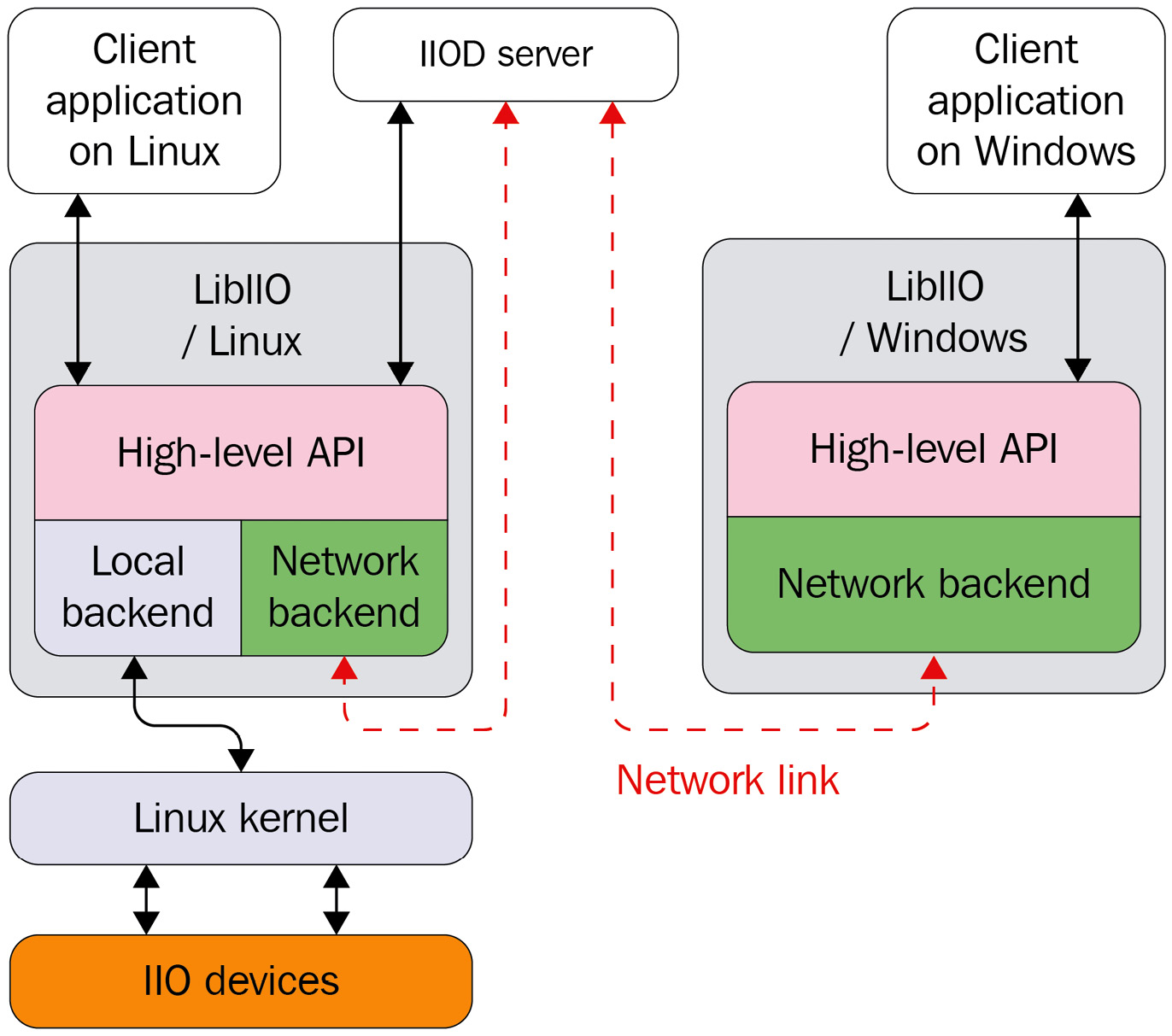
Figure 15.2 – libiio overview
libiio is built around five concepts, each of which corresponds to a data structure, altogether making almost all the API. These concepts are the following:
- The backend: This represents the connectivity (or the communication channel) between your application and the target on which the IIO devices to interact with are connected. This backend (thus connectivity) can be via USB, network, serial, or local. Independently from the hardware connectivity available, supported backends are library compile-time defined.
- The context: A context is a library instance that represents a collection of IIO devices, which in most cases correspond to a global view of the IIO devices on a running target. In this way, a context gathers all the IIO devices the target contains, as well as their channels and their attributes. For instance, when looking for an IIO device, code must create a context and request the target IIO device from this context.
Because applications may run remotely to the target board, the context will need a communication channel with that target. This is where the backend intervenes. Therefore, a context must be backed by a backend, which represents the connectivity between the target and the machine running the application. However, remotely running applications are not always aware of the target environment; thus, the library allows look up for available backends, allowing, among other things, dynamic behavior. This lookup is referred to as IIO context scanning. That said, applications may not bother with scanning if running locally to the target.
A context is represented with an instance of struct iio_context. A context object may contain zero or more devices. However, a device object is associated with only one context.
- The device: This is the IIO device. It is represented with struct iio_device, which is the user-space (libiio actually) counterpart of the in-kernel struct iio_dev. A device object may contain zero or more channels, while a channel is associated with only one device.
- The buffer: A buffer allows continuous data capture and chunk- (or slot-, instead of channel-) based reading. Such an object is represented with an instance of struct iio_buffer. A device may be associated with one buffer object, and a buffer is associated with only one device.
- The channel: A channel is an acquisition line, represented by an instance of struct iio_channel. A device may contain zero or more channels, and a channel is associated with only one device.
After becoming familiar with these concepts, we can split IIO application development into the following steps:
- Creating a context, after having (optionally) scanned for available backends to create this context with.
- Iterating over all devices, or looking for and picking the one of interest. Eventually getting/setting the device parameters via its attributes.
- Walking through the device channels and enabling channels of interest (or disabling the ones we are not interested in). Eventually getting/setting the channel parameters via their attributes.
- If a device needs a trigger, then associating a trigger with the given device. This trigger must have been created before creating the context.
- Creating a buffer and associating this buffer with the device, and then starting streaming.
- Starting the capture and reading the data.
Scanning and creating an IIO context
When creating a context, the library will identify the IIO devices (including triggers) that can be used and identify the channels for each device; then, it will identify all device- and channel-specific attributes and also identify attributes shared by all channels; finally, the library will create a context where all those entities are placed.
A context can be created using one of the following APIs:
iio_create_local_context()
iio_create_network_context()
iio_create_context_from_uri()
iio_context_clone(const struct iio_context *ctx)
Each of these functions returns a valid context object on success and NULL otherwise, with errno set appropriately. That said, while they all return the same values, their arguments may vary, as described in the following:
- iio_create_local_context(): Used to create a local context:
struct iio_context * local_ctx;
local_ctx = iio_create_local_context();
Note that the local backend interfaces the Linux kernel through the sysfs virtual filesystem.
- iio_create_network_context(): Creates a network context. It takes as a parameter a string representing the IPv4 or IPv6 network address of the remote target:
struct iio_context * network_ctx;
network_ctx =
iio_create_network_context("192.168.100.15");
- USB context can be created using an URI-based API, iio_create_context_from_uri(). The argument is a string identifying the USB device using the following pattern – usb:[device:port:instance]:
struct iio_context * usb_ctx;
usb_ctx = iio_create_context_from_uri("usb:3.80.5");
- A serial context, like a USB context, uses a URI-based API. However, its URI must match the following pattern – serial:[port][,baud][,config]:
struct iio_context * serial_ctx;
serial_ctx = iio_create_context_from_uri(
"serial:/dev/ttyUSB0,115200,8n1");
- iio_create_context_from_uri() is a URI-based API, taking as a parameter a valid URI (starting with the backend to use). For local context, the URI must be "local:". For a URI-based network context, the URI pattern must match "ip:<ipaddr>", where <ipaddr> is the IPv4 or IPv6 of the remote target. More information on URI-based contexts can be found here: https://analogdevicesinc.github.io/libiio/v0.21/libiio/group__Context.html#gafdcee40508700fa395370b6c636e16fe.
- iio_context_clone() duplicates the context given as a parameter and returns the new clone. This function is not supported on usb: contexts, since libusb can only claim the interface once.
Before creating a context, the user might be interested in scanning the available contexts (that is, looking for available backends). To find what IIO contexts are available, the user code must do the following:
- Invoke iio_create_scan_context() to create an instance of iio_scan_context object. The first argument to this function is a string that is used as a filter (usb:, ip:, local:, serial:, or a mix, such as usb:ip, where the default (NULL) means any backend that is compiled in).
- Call iio_scan_context_get_info_list() given the previous iio_scan_context object as parameter. This will return an array iio_context_info object from the iio_scan_context object. Each iio_context_info object can be examined with iio_context_info_get_description() and iio_context_info_get_uri() to determine which URI you want to attach to.
- Once done, the info object array and the scan object must be released with iio_context_info_list_free() and iio_scan_context_destroy(), respectively.
The following is a demonstration of scanning available contexts and creating one:
int i;
ssize_t nb_ctx;
const char *uri;
struct iio_context *ctx = NULL;
#ifdef CHECK_REMOTE
struct iio_context_info **info;
struct iio_scan_context *scan_ctx =
iio_create_scan_context("usb:ip:", 0);
if (!scan_ctx) {
printf("Unable to create scan context! ");
return NULL;
}
nb_ctx = iio_scan_context_get_info_list(scan_ctx, &info);
if (nb_ctx < 0) {
printf("Unable to scan! ");
iio_scan_context_destroy(scan_ctx);
return NULL;
}
for (i = 0; i < nb_ctx; i++) {
uri = iio_context_info_get_uri(info[0]);
if (strcmp ("usb:", uri) == 0) {
ctx = iio_create_context_from_uri(uri);
break;
}
if (strcmp ("ip:", uri) == 0) {
ctx =
iio_create_context_from_uri("ip:192.168.3.18");
break;
}
}
iio_context_info_list_free(info);
iio_scan_context_destroy(scan_ctx);
#endif
if (!ctx) {
printf("creating local context ");
ctx = iio_create_local_context();
if (!ctx) {
printf("unable to create local context ");
goto err_free_info_list;
}
}
return ctx;
In the preceding code, if the CHECK_REMOTE macro is defined, the code will first scan for available contexts (that is, backends) by filtering USB and network ones. The code first looks for the USB context before looking for a network context. If none is available, it falls back to a local context.
In addition, you can get some context-related information using the following APIs:
int iio_context_get_version (
const struct iio_context * ctx,
unsigned int *major, unsigned int *minor,
char git_tag[8])
const char * iio_context_get_name(
const struct iio_context *ctx)
const char * iio_context_get_description(
const struct iio_context *ctx)
In the preceding APIs, iio_context_get_version() returns the version of the backend in use into major, minor, and git_tag output arguments, and iio_context_get_name() returns a pointer to a static NULL-terminated string corresponding to the backend name, which can be local, xml, or network when the context has been created with the local, XML, and network backends, respectively.
The following is a demonstration:
unsigned int major, minor;
char git_tag[8];
struct iio_context *ctx;
[...] /* the context must be created */
iio_context_get_version(ctx, &major, &minor, git_tag);
printf("Backend version: %u.%u (git tag: %s) ",
major, minor, git_tag);
printf("Backend description string: %s ",
iio_context_get_description(ctx));
Now that the context has been created, and we are able to read its information, the user might be interested in walking through it, that is, navigating the entities this context is made of, for instance, getting the number of IIO devices or getting an instance of a given device.
Note
A context is a punctual and fixed view of IIO entities on the target. For instance, if a user creates an IIO trigger device after having created the context, this trigger device won't be accessible from this context. Because there is no context synchronization API, the proper way to do things would be to destroy and re-create things or to create the needed dynamic IIO elements at the beginning of the program before creating the context.
Walking through and managing IIO devices
The following are APIs to navigate through the devices in an IIO context:
unsigned int iio_context_get_devices_count(
const struct iio_context *ctx)
struct iio_device * iio_context_get_device(
const struct iio_context *ctx, unsigned int index)
struct iio_device * iio_context_find_device(
const struct iio_context *ctx, const char *name)
From a context, iio_context_get_devices_count() returns the number of IIO devices in this context.
iio_context_get_device() returns a handle for an IIO device specified by its index (or ID). This ID corresponds to <X> in /sys/bus/iio/devices/iio:device<X>/. For example, the ID of the /sys/bus/iio/devices/iio:device1 device is 1. If the index is invalid, NULL is returned. Alternatively, given a device object, its ID can be retrieved with iio_device_get_id().
iio_context_find_device() looks for an IIO device by its name. This name must correspond to the name specified in iio_indev->name specified in the driver. You can obtain this name either by using a dedicated iio_device_get_name() API or by reading the name attribute in this device's sysfs directory:
root:/sys/bus/iio/devices/iio:device1> cat name
ad9361-phy
The following is an example of going through all devices and printing their names and IDs:
struct iio_context * local_ctx;
local_ctx = iio_create_local_context();
int i;
for (i = 0; i < iio_context_get_devices_count(local_ctx);
++i) {
struct iio_device *dev =
iio_context_get_device(local_ctx, i);
const char *name = iio_device_get_name(dev);
printf(" %s: %s ", iio_device_get_id(dev), name );
}
iio_context_destroy(ctx);
The preceding code example iterates over IIO devices present in the context (a local context) and prints their names and IDs.
Walking through and managing IIO channels
The main channel management APIs are the following:
unsigned int iio_device_get_channels_count(
const struct iio_device *dev)
struct iio_channel* iio_device_get_channel(
const struct iio_device *dev, unsigned int index)
struct iio_channel* iio_device_find_channel(
const struct iio_device *dev,
const char *name, bool output)
We can get the number of available channels from an iio_device object thanks to iio_device_get_channels_count(). Then, each iio_channel object can be accessed with iio_device_get_channel(), specifying the index of this channel. For example, on a three-axis (x, y, z) accelerometer, iio_device_get_channel(iio_device, 0) will correspond to getting channel 0, that is, accel_x. On an eight-channel ADC converter, iio_device_get_channel(iio_device, 0) will correspond to getting channel 0, that is, voltage0.
Alternatively, it is possible to look up a channel by its name using iio_device_find_channel(), which expects in arguments the channel name and a Boolean, which tells you whether the channel is an output or not. If you remember, in the Channel attribute naming convention section, we saw that attribute names respect the following pattern: {direction}_{type}{index}_{modifier}_{info_mask}. The subset in this pattern that needs to be used with iio_device_find_channel() is {type}{index}_{modifier}. Then, depending on the value of the Boolean parameter, the final name will be obtained by adding either in_ or out_ as a prefix. For instance, to obtain channel X of the accelerometer, we would use iio_device_find_channel(iio_device, "accel_x", 0). For the first channel of the analog-to-digital converter, we would use iio_device_find_channel(iio_device, "voltage0", 0).
The following is an example of going through all devices and all channels of each device:
struct iio_context * local_ctx;
struct iio_channel *chan;
local_ctx = iio_create_local_context();
int i, j;
for (i = 0; i < iio_context_get_devices_count(local_ctx);
++i) {
struct iio_device *dev =
iio_context_get_device(local_ctx, i);
printf("Device %d ", i);
for (j = 0; j < iio_device_get_channels_count(dev);
++j) {
chan = iio_device_get_channel(dev, j);
const char *name = iio_channel_get_name(ch) ? :
iio_channel_get_id(ch);
printf(" channel %d: %s ", j, name);
}
}
The preceding code creates a local context and walks through all the devices in this context. Then, for each device, it iterates over channels and prints their name.
Additionally, there are miscellaneous APIs allowing us to obtain channel properties. These are the following:
bool iio_channel_is_output(const struct iio_channel *chn);
const char* iio_channel_get_id(
const struct iio_channel *chn);
enum iio_modifier iio_channel_get_modifier(
const struct iio_channel *chn);
enum iio_chan_type iio_channel_get_type(
const struct iio_channel *chn);
const char* iio_channel_get_name(
const struct iio_channel *chn);
In the preceding APIs, the first one checks whether the IIO channel is output or not, and the others mainly return each of the elements the name pattern is made of.
Working with a trigger
In libiio, a trigger is assimilated to a device, as both are represented by struct iio_device. The trigger must be created before creating the context, else this trigger won't be seen/available from that context.
In order to do so, you must create the trigger yourself, as we saw in the IIO trigger and sysfs (user space) section. Then, to find this trigger from a context, as it is assimilated to a device, you can use one of the device-related lookup APIs that we described in the Walking through and managing IIO devices section. In this section, let's use iio_context_find_device(), which as you'll recall is defined as the following:
struct iio_device* iio_context_find_device(
const struct iio_context *ctx, const char *name)
This function looks for a device by its name in the given context. This is the reason why the trigger must have been created before creating the context. In parameters, ctx is the context from where to look for the trigger and name is the name of the trigger, as you would have written it to the current_trigger sysfs file.
Once the trigger found, it must be assigned to a device using iio_device_set_trigger(), defined as the following:
int iio_device_set_trigger(const struct iio_device *dev,
const struct iio_device *trig)
This function associates the trigger, trig, to the device, dev, and returns 0 on success or a negative errno code on failure. If the trig parameter is NULL, then any trigger associated with the given device will be disassociated. In other words, to disassociate a trigger from the device, you should call iio_device_set_trigger(dev, NULL).
Let's see how trigger lookup and association work in a little example:
struct iio_context *ctx;
struct iio_device *trigger, *dev;
[...]
ctx = iio_create_local_context();
/* at least 2 iio_device must exist:
* a trigger and a device */
if (!(iio_context_get_devices_count(ctx) > 1))
return -1;
trigger = iio_context_find_device(ctx, "hrtimer-1");
if (!trigger) {
printf("no trigger found ");
return -1;
}
dev = iio_context_find_device(ctx, "iio-device-dummy");
if (!dev) {
printf("unable to find the IIO device ");
return -1;
}
printf("Enabling IIO buffer trigger ");
iio_device_set_trigger(dev, trigger);
[...]
/* When done with the trigger */
iio_device_set_trigger(dev, NULL);
In the preceding example, we first create a local context, and we make sure this context contains at least two devices. Then, from this context, we look for a trigger named hrtimer-1 and a device named iio-device-dummy. Once both are found, we associate the trigger to the device. Finally, when done with the trigger, it is disassociated from the device.
Creating a buffer and reading data samples
Note that channels we are interested in need to be enabled before creating the buffer. To do so, you can use the following APIs:
void iio_channel_enable(struct iio_channel * chn)
bool iio_channel_is_enabled(struct iio_channel * chn)
The first function enables the channel so that its data will be captured and pushed in the buffer. The second one is a helper checking whether a channel has already been enabled or not.
In order to disable a channel, you can use iio_channel_disable(), defined as the following:
void iio_channel_disable(struct iio_channel * chn)
Now that we are able to enable the channels, we need their data to be captured. We can create a buffer using iio_device_create_buffer(), defined as the following:
struct iio_buffer * iio_device_create_buffer(
const struct iio_device *dev,
size_t samples_count, bool cyclic)
This function configures and enables a buffer. In the preceding function, samples_count is the total number of data samples that can be stored by the buffer, whatever the number of enabled channels. It corresponds to the length attribute described in the IIO buffer sysfs interface section. cyclic, if true, enables cyclic mode. This mode makes sense for output devices only (such as DACs). However, in this section, we deal with input devices only (that is, ADCs).
Once you are done with a buffer, you can call iio_buffer_destroy() on this buffer, which disables it (thus stopping the capture) and frees the data structure. This API is defined as the following:
void iio_buffer_destroy(struct iio_buffer *buf)
Do note that capturing starts as soon as the buffer is created, that is, after iio_device_create_buffer() has succeeded. However, samples are only pushed into the kernel buffers. In order to fetch samples from the kernel buffer to the user-space buffer, we need to use iio_buffer_refill(). While iio_device_create_buffer() has to be called only once to create the buffer and start the in-kernel continuous capture, iio_buffer_refill() must be called every time we need to fetch samples from the kernel buffer. It could be used in the processing loop, for example. The following is its definition:
ssize_t iio_buffer_refill (struct iio_buffer *buf)
With iio_device_create_buffer(), with the low-speed interface, the kernel allocates a single underlying buffer block (whose size equals samples_count * nb_buffers * sample_size) to handle the captures and immediately starts feeding samples inside. This default block count is 4 by default, and can be changed with iio_device_set_kernel_buffers_count(), defined as the following:
int iio_device_set_kernel_buffers_count(
const struct iio_device *dev,
unsigned int nb_buffers)
In high-speed mode, the kernel allocates nb_buffers buffer blocks, managed with the FIFO concept of an input queue (empty buffers) and output queue (buffers containing samples) in a way that, upon creation, all the buffers are filled with samples and put in the outgoing queue. When iio_buffer_refill() is called, the first buffer's data in the output queue is pushed (or mapped) to user space and this buffer is put back in the input queue waiting to be filled again. At the next call to iio_buffer_refill(), the second one is used, and so on, over and over. It must be noted that small buffers result in less latency but more overhead, while large buffers result in less overhead but more latency. The application must make tradeoffs between latency and management overhead. When cyclic mode is true, only a single buffer will be created, whatever the number of blocks specified.
In order to read the data samples, the following APIs can be used:
void iio_buffer_destroy(struct iio_buffer *buf)
void* iio_buffer_end(const struct iio_buffer *cbuf)
void* iio_buffer_start(const struct iio_buffer *buf)
ptrdiff_t iio_buffer_step(const struct iio_buffer *buf)
void* iio_buffer_first(const struct iio_buffer *buf,
const struct iio_channel *chn)
ssize_t iio_buffer_foreach_sample(struct iio_buffer *buf,
ssize_t(*callback)(const struct iio_channel *chn,
void *src, size_t bytes, void *d),
void *data)
The following are the meanings and usages of each API listed:
- iio_buffer_end() returns a pointer corresponding to the user-space address that immediately follows the last sample present in the buffer.
- iio_buffer_start() returns the address of the user-space buffer. Do, however, note that this address might change after iio_buffer_refill() (especially with a high-speed interface, where several buffer blocks are used).
- iio_buffer_step() returns the spacing between sample sets in the buffer. That is, it returns the difference between the addresses of two consecutive samples of one same channel.
- iio_buffer_first() returns the address of the first sample for a channel or the address of the end of the buffer if no sample for the given channel is present in the buffer.
- iio_buffer_foreach_sample() iterates over each sample in a buffer and calls a supplied callback for each sample found.
The preceding list of APIs can be split into three families, depending on how the data samples are read.
Buffer pointer reading
In this read method, iio_buffer_first() is coupled with iio_buffer_step() and iio_buffer_end() in order to iterate on all the samples of a given channel present in the buffer. This can be achieved in the following manner:
for (void *ptr = iio_buffer_first(buffer, chan);
ptr < iio_buffer_end(buffer);
ptr += iio_buffer_step(buffer)) {
[...]
}
In the preceding example, from within the loop, ptr will point to one sample of the channel we're interested in, that is, chan.
The following is an example:
const struct iio_data_format *fmt;
unsigned int i, repeat;
struct iio_channel *channels[8] = {0};
ptrdiff_t p_inc;
char *p_dat;
[...]
IIOC_DBG("Enter buffer refill loop. ");
while (true) {
nbytes = iio_buffer_refill(buf);
p_inc = iio_buffer_step(buf);
p_end = iio_buffer_end(buf);
for (i = 0; i < channel_count; ++i) {
fmt = iio_channel_get_data_format(channels[i]);
repeat = fmt->repeat ? : 1;
for (p_dat = iio_buffer_first(rxbuf, channels[i]);
p_dat < p_end; p_dat += p_inc) {
for (j = 0; j < repeat; ++j) {
if (fmt->length/8 == sizeof(int16_t))
printf("Read 16bit value: " "%" PRIi16,
((int16_t *)p_dat)[j]);
else if (fmt->length/8 == sizeof(int64_t))
printf("Read 64bit value: " "%" PRIi64,
((int64_t *)p_dat)[j]);
}
}
}
printf(" ");
}
The preceding code reads the channel data format to check whether the value is repeated or not. This repeat corresponds to iio_chan_spec.scan_type.repeat. Then, assuming the code could work with two variants of a converter (the first one coding data on 16 bits and the second coding data on 64 bits), a check for the data length is performed to print in the appropriate format. This length corresponds to iio_chan_spec.scan_type.storagebits. Do note that PRIi16 and PRIi64 are the integer printf formats for int16_t and int64_t, respectively.
Callback-based sample reading
In callback-based sample reading, iio_buffer_foreach_sample() is at the heart of the reading logic. It has the following definition:
ssize_t iio_buffer_foreach_sample(struct iio_buffer *buf,
ssize_t(*)(const struct iio_channel *chn,
void *src, size_t bytes, void *d) callback,
void *data)
This function calls the supplied callback for each sample found in a buffer. data is user data, which, if set, will be passed to the callback in the last argument. This function iterates over samples, and each sample is read and passed to a callback, along with the channel from where this sample originates. This callback has the following definition:
ssize_t sample_cb(const struct iio_channel *chn,
void *src, size_t bytes, __notused void *d)
The callback receives four arguments, as follows:
- A pointer to the iio_channel structure that produced the sample
- A pointer to the sample itself
- The length of the sample in bytes, that is, the storage bits divided by 8, iio_chan_spec.scan_type.storagebits/8
- The user-specified pointer optionally passed to iio_buffer_foreach_sample()
This method may be used to read from (in the case of input devices) or write to (in the case of output devices) the buffer. The main difference from the previous method is that the callback function is invoked for each sample of the buffer, not ordered by channels, but in the order that they appear in the buffer.
The following is an example of this kind of callback implementation:
static ssize_t sample_cb(const struct iio_channel *chn,
void *src, size_t bytes, __notused void *d)
{
const struct iio_data_format *fmt =
iio_channel_get_data_format(chn);
unsigned int j, repeat = fmt->repeat ? : 1;
printf("%s ", iio_channel_get_id(chn));
for (j = 0; j < repeat; ++j) {
if (bytes == sizeof(int16_t))
printf("Read 16bit value: " "%" PRIi16,
((int16_t *)src)[j]);
else if (bytes == sizeof(int64_t))
printf("Read 64bit value: " "%" PRIi64,
((int64_t *)src)[j]);
}
return bytes * repeat;
}
Then, in the main code, we loop and iterate over samples in the buffer, as follows:
int ret;
[...]
IIOC_DBG("Enter buffer refill loop. ");
while (true) {
nbytes = iio_buffer_refill(buf);
ret = iio_buffer_foreach_sample(buf, sample_cb, NULL);
if (ret < 0) {
char text[256];
iio_strerror(-ret, buf, sizeof(text));
printf("%s (%d) while processing buffer ",
text, ret);
}
printf(" ");
}
The preceding code, instead of playing with samples directly, delegates the job to a callback.
High-level channel (raw) reading
The last method in this read series is to use one of the higher-level functions provided by the iio_channel class. These are iio_channel_read_raw(), iio_channel_write_raw(), iio_channel_read(), and iio_channel_write(), all defined as the following:
size_t iio_channel_read_raw(const struct iio_channel *chn,
struct iio_buffer *buffer, void *dst, size_t len)
size_t iio_channel_read(onst struct iio_channel *chn,
struct iio_buffer *buffer, void *dst, size_t len)
size_t iio_channel_write_raw(const struct iio_channel *chn,
struct iio_buffer * buffer, const void *src,
size_t len)
size_t iio_channel_write(const struct iio_channel *chn,
struct iio_buffer *buffer, const void *src,
size_t len)
The former two will basically copy the first N samples of a channel (chan) to a user-specified buffer (dst), which must have been allocated beforehand (N depending on the size of this buffer and a sample's storage size, that is, iio_chan_spec.scan_type.storagebits / 8). The difference between the two is that the _raw variant won't convert the samples and the user buffer will contain raw data, while the other variant will convert each sample so that the user buffer will contain processed values. These functions kind of demultiplex (since they target one channel's samples among several ones) samples of a given channel.
On the other hand, iio_channel_write_raw() and iio_channel_write() will copy the sample data from the user-specified buffer to the device, by targeting a given channel. These functions multiplex the samples as they gather samples targeting one channel among many. The difference between the two is that the _raw variant will copy data as is and the other will convert the data into hardware format before sending it to the device.
Let's try to use the preceding APIs to read data from a device:
#define CBUF_LENGTH 2048 /* the number of sample we need */
[...]
const struct iio_data_format *fmt;
unsigned int i, repeat;
struct iio_channel *chan[8] = {0};
[...]
IIOC_DBG("Enter buffer refill loop. ");
while (true) {
nbytes = iio_buffer_refill(buf);
for (i = 0; i < channel_count; ++i) {
uint8_t *c_buf;
size_t sample, bytes;
fmt = iio_channel_get_data_format(chan[i]);
repeat = fmt->repeat ? : 1;
size_t sample_size = fmt->length / 8 * repeat;
c_buf = malloc(sample_size * CBUF_LENGTH);
if (!c_buf) {
printf("No memory space for c_buf ");
return -1;
}
if (buffer_read_method == CHANNEL_READ_RAW)
bytes = iio_channel_read_raw(chan[i], buf,
c_buf, sample_size * CBUF_LENGTH);
else
bytes = iio_channel_read(chan[i], buf, c_buf,
sample_size * CBUF_LENGTH);
printf("%s ", iio_channel_get_id(chan[i]));
for (sample = 0; sample < bytes / sample_size;
++sample) {
for (j = 0; j < repeat; ++j) {
if (fmt->length / 8 == sizeof(int16_t))
printf("%" PRIi16 " ",
((int16_t *)buf)[sample+j]);
else if (fmt->length / 8 == sizeof(int64_t))
printf("%" PRId64 " ",
((int64_t *)buf)[sample+j]);
}
}
free(c_buf);
}
printf(" ");
}
In the preceding example, we first fetch data samples from the kernel using iio_buffer_refill(). Then, for each channel, we obtain the data format of this channel using iio_channel_get_data_format(), from which we grab the size of a sample for this channel. After that, we use this sample's size to compute the user buffer size to allocate for receiving this channel's samples. Obtaining a channel's sample size allows us to precisely determine the size of the user buffer to allocate.
Walking through user-space IIO tools
Though we have already gone through the steps required to capture IIO data, it might be tedious and confusing since each step must be performed manually. There are some useful tools you can use to ease and speed up your app development dealing with IIO devices. These are all from the libiio package, developed by Analog Devices, Inc. to interface IIO devices, available here: https://github.com/analogdevicesinc/libiio.
User-space applications can easily use the libiio library, which under the hood is a wrapper that relies on the following interfaces:
- /sys/bus/iio/devices, the IIO sysfs interface, which is mainly used for configuration/settings
- The /dev/iio/deviceX character device, for data/acquisitions
The preceding are exactly what we have manually dealt with so far. The tool's source code can be found under the library's tests directory: https://github.com/analogdevicesinc/libiio/tree/master/tests offers tools such as the following:
- The iiod server daemon, acting as a network backend to serve any application over a network link
- iio_info to dump attributes
- iio_readdev to read or scan from a device
We ended this chapter by enumerating tools, which can ease prototyping or device/driver testing. Links pointing to either sources, documentation, or examples of usage of these tools have been mentioned.
Summary
After reading this chapter, you are familiar with the IIO framework and vocabulary. You know what channels, devices, and triggers are. You can even play with your IIO device from the user space, through sysfs or a character device. The time to write your own IIO driver has come. There are a lot of available existing drivers that don't support trigger buffers. You can try to add this feature to one of them.
In the next chapter, we will play with the GPIO subsystem, which is a basic concept that has been introduced in this chapter as well.