Chapter 7
Configuring High Availability
THE FOLLOWING 70-741 EXAM OBJECTIVES ARE COVERED IN THIS CHAPTER:
 Implement high performance network solutions
- This objective may include but is not limited to: Implement NIC Teaming or the Switch Embedded Teaming (SET) solution and identify when to use each; enable and configure Receive Side Scaling (RSS); enable and configure network Quality of Service (QoS) with Data Center Bridging (DCB); enable and configure SMB Direct on Remote Direct Memory Access (RDMA) enabled network adapters; enable and configure SMB Multichannel; enable and configure virtual Receive Side Scaling (vRSS) on a Virtual Machine Queue (VMQ) capable network adapter; enable and configure Virtual Machine Multi-Queue (VMMQ); enable and configure Single Root I/O Virtualization (SR-IOV) on a supported network adapter.
 In this chapter, I will show you some of the techniques and components of high availability. I will explain how to set up high availability and I will talk about some of the reasons why you would choose to use high availability. I will also show you how to use PowerShell for high availability.
I will continue the chapter by explaining how to keep your Hyper-V servers up and running by implementing high availability and disaster recovery options in Hyper-V. Finally I will show you the PowerShell commands for Hyper-V high availability.
Components of High Availability
High availability is a buzzword that many application and hardware vendors like to throw around to get you to purchase their products. Many different options are available to achieve high availability, and there also seems to be a number of definitions and variations that help vendors sell their products as high-availability solutions.
When it comes right down to it, however, high availability simply means providing services with maximum uptime by avoiding unplanned downtime. Often, disaster recovery (DR) is also closely lumped into discussions of high availability, but DR encompasses the business and technical processes that are used to recover once a disaster has happened.
Defining a high availability plan usually starts with a service level agreement (SLA). At its most basic, an SLA defines the services and metrics that must be met for the availability and performance of an application or service. Often, an SLA is created for an IT department or service provider to deliver a specific level of service. An example of this might be an SLA for a Microsoft Exchange Server. The SLA for an Exchange Server might have uptime metrics on how much time during the month the mailboxes need to be available to end users, or it might define performance metrics for the amount of time it takes for email messages to be delivered.
When determining what goes into an SLA, two other factors need to be considered. However, you will often see them discussed only in the context of disaster recovery, even though they are important for designing a highly available solution. These factors are the recovery point objective (RPO) and the recovery time objective (RTO).
An RTO is the length of time an application can be unavailable before service must be restored to meet the SLA. For example, a single component failure would have an RTO of less than five minutes, and a full-site failure might have an RTO of three hours. An RPO is essentially the amount of data that must be restored in the event of a failure. For example, in a single server or component failure, the RPO would be 0, but in a site failure, the RPO might allow for up to 20 minutes of lost data.
SLAs, on the other hand, are usually expressed in percentages of the time the application is available. These percentages are also often referred to by the number of nines the percentage includes. So if someone told you that you need to make sure that the router has a rating of Five 9s, that would mean that the router could only be down for 5.26 minutes a year. Table 7.1 shows you some of the different nines ratings and what each rating allows for downtime.
TABLE 7.1 Availability percentages
| Availability Rating | Allowed Unplanned Downtime/Year |
| 99 (two nines) percent | 3.65 days |
| 99.9 (three nines) percent | 8.76 hours |
| 99.99 (four nines) percent | 52.56 minutes |
| 99.999 (five nines) percent | 5.26 minutes |
| 99.9999 (six nines) percent | 31.5 seconds |
| 99.99999 (seven nines) percent | 3.15 seconds |
Two important factors that affect an SLA are the mean time between failure (MTBF) and the mean time to recovery (MTTR). To be able to reduce the amount of unplanned downtime, the time between failures must be increased, and the time it takes to recover must be reduced. Modifying these two factors will be addressed in the next several sections of this chapter.
Achieving High Availability
Windows Server 2016 is the most secure and reliable Windows version to date. It also is the most stable, mature, and capable of any version of Windows. Although similar claims have been made for previous versions of Windows Server, you can rest assured that Windows Server 2016 is much better than previous versions for a variety of reasons.
An honest look at the feature set and real-world use should prove that this latest version of Windows provides the most suitable foundation for creating a highly available solution. However, more than just good software is needed to be able to offer high availability for applications.
High Availability Foundation
Just as a house needs a good foundation, a highly available Windows server needs a stable and reliable hardware platform on which to run. Although Windows Server 2016 will technically run on desktop-class hardware, high availability is more easily achieved with server-class hardware. What differentiates desktop-class from server-class hardware? Server-class hardware has more management and monitoring features built into it so that the health of the hardware is capable of being monitored and maintained.
Another large difference is that server-class hardware has redundancy options. Server-class hardware often has options to protect from drive failures, such as RAID controllers, and to protect against power supply failures, such as multiple power supplies. Enterprise-class servers have even more protection.
More needs to be done than just installing Windows Server 2016 to ensure that the applications remain running with the best availability possible. Just as a house needs maintenance and upkeep to keep the structure in proper repair, so too does a server. In the case of a highly available server, this means patch management.
Installing Patches
Microsoft releases monthly updates to fix security problems with its software, both for operating system fixes and for applications. To ensure that your highly available applications are immune to known vulnerabilities, these patches need to be applied in a timely manner during a scheduled maintenance window. Also, to address stability and performance issues, updates and service packs are released regularly for many applications, such as Microsoft SQL Server, Exchange Server, and SharePoint Portal Server. Many companies have a set schedule—daily, weekly, or monthly—to apply these patches and updates after they are tested and approved.
Desired Configuration Manager (DCM), an option in Microsoft System Center Configuration Manager, is a great tool for helping to validate that your cluster nodes are patched. It can leverage the SCCM client to collect installed patches and help reporting within the enterprise on compliancy with desired system states based on the software installed.
To continue with the house analogy, if you were planning to have the master bath remodeled, would you rather hire a college student on spring break looking to make some extra money to do the job or a seasoned artisan? Of course, you would want someone with experience and a proven record of accomplishment to remodel your master bath.
Likewise, with any work that needs to be done on your highly available applications, it’s best to hire only decidedly qualified individuals. This is why obtaining a Microsoft certification is definitely an excellent start to becoming qualified to configure a highly available server properly. There is no substitute for real-life and hands-on experience. Working with highly available configurations in a lab and in production will help you know not only what configurations are available but also how the changes should be made.
For example, it may be possible to use Failover Clustering for a DNS server, but in practice DNS replication may be easier to support and require less expensive hardware in order to provide high availability. This is something you would know only if you had enough experience to make this decision.
As with your house, once you have a firm and stable foundation built by skilled artisans and a maintenance plan has been put into place, you need to ascertain what more is needed. If you can’t achieve enough uptime with proper server configuration and mature operational processes, a cluster may be needed.
Windows Server 2016 provides two types of high availability: Failover Clustering and Network Load Balancing (NLB). Failover clustering is used for applications and services such as SQL Server and Exchange Server. Network Load Balancing is used for network-based services such as web and FTP servers. The remaining sections of this chapter will cover NLB and Hyper-V high availability in depth.
Understanding Network Load Balancing
So the first thing we have to discuss is why an administrator would choose to use NLB. NLB allows an administrator to configure two or more servers as a single virtual cluster. NLB is designed for high availability and scalability of Internet server applications. So this means that Windows Server 2016 NLB is designed to work with web servers, FTP servers, firewalls, proxy servers, and virtual private networks (VPNs).
Network Load Balancing is a form of clustering where the nodes are highly available for a network-based service. This is typically a port listener configuration where a farm of, say, Microsoft Internet Information Services servers all listen on ports 80 and 443 for incoming web traffic from client endpoints. These nodes, while not fully clustered in a technical sense, are load balanced, where each node handles some of the distributed network traffic.
The NLB feature uses the TCP/IP networking protocol to distribute traffic. For web servers and other necessary servers, NLB can provide performance and consistency when two or more computers are combined into a single virtual cluster.
Hosts are servers that make up an NLB cluster. Each host runs their own individual copy of the server applications. The incoming client requests are distributed by NLB to each of the hosts in the cluster. The administrator can configure the load so that it is handled by each host. Hosts can be added to the cluster to increase the load. If NLB has all traffic directed to a specific single host, then it is called a default host.
With the use of NLB, all the computers in a cluster can use the same set of IP addresses while each host maintains its own exclusive IP address. When a host fails for load-balanced applications, the computers still in operation will receive the workload automatically. When the down computer is ready to rejoin the cluster it comes back online and will regain its share of the workload. This allows the rest of the computers in the cluster to handle less traffic.
NLB is beneficial in that stateless applications (for example, web servers) are available with little downtime and it allows for scalability.
Scalability is the capability of a system, network, or process to handle a growing amount of work, or its potential to be enlarged in order to accommodate growth. Scalability, when used for NLB clusters, is the ability to add one or more systems to an existing cluster when the need arises. An administrator can do the following with NLB to support scalability:
- A single cluster can support up to 32 computers.
- Handle multiple server load requests from across multiple hosts in a cluster.
- For single TCP/IP services, balance load requests across the NLB cluster.
- As the workload grows, be able to add hosts to the NLB cluster without failure.
- When the workload declines, be able to remove hosts from the cluster.
- Allow higher performance and lower overhead by utilizing a pipelined implementation. Pipelining allows requests to be sent to the NLB cluster without waiting for a response.
- Use NLB Manager or Windows PowerShell cmdlets to manage and configure NLB clusters and hosts from a single computer.
- Determine port rules for each website. Port rules allow you to configure which ports are going to be enabled or disabled. Ports are doorways that applications can use to access resources. For example, DNS traffic uses port 53 for all DNS traffic. Here are some of the more common port numbers:
- FTP uses ports 20/21
- Secure Shell uses port 22
- SMTP (mail) uses port 25
- DNS uses port 53
- HTTP uses port 80
- POPv3 uses port 110
- HTTPS uses port 443
- Determine load balancing behavior using port management rules for an IP port or group of ports.
- Use an optional, single-host rule that will direct all client requests to a single host. NLB will route client requests to a specific host that is running particular applications.
- Allow certain IP ports to block unwanted network access.
- When operating in multicast mode, enable Internet Group Management Protocol (IGMP) support on the cluster host. This will control switch port flooding (when all incoming network packets are sent to all ports on the switch).
- Use Windows PowerShell to start, stop and control NLB actions remotely.
- Check NLB events using Windows Event Log. All NLB actions and cluster changes are logged in the Event Log.
NLB Requirements
NLB cluster hardware requirements:
- All hosts must be on the same subnet.
- For each host, there is no limitation to the number of network adapters.
- All network adapters must be multicast or unicast within the cluster. Mixed environments, within a single cluster, are NOT supported.
- If using unicast mode, the network adapter used to handle client-to-cluster traffic must support media access control (MAC) address changing.
NLB cluster software requirements:
- The adapter on which NLB is enabled can only support TCP/IP.
- Must have a static IP address on the servers in the cluster.
Installing NLB Nodes
You can install NLB nodes like any other server build. Administrators can install NLB by using either Server Manager or the Windows PowerShell commands for NLB.
Administrators should first make sure that all NLB servers have the most current updates, provisioned with appropriate resources (typically with multiple network interface cards for capacity and responsiveness), and monitored for health and reliability. In Exercise 7.1, I will walk you through the installation of your NLB nodes.
If you decide that you want to install NLB using Windows PowerShell commands, you would open an elevated Windows PowerShell prompt and type in the following command:
Install-WindowsFeature NLB -IncludeManagementTools
Upgrading an NLB Cluster
Upgrading an NLB cluster is a fairly straightforward process. The first thing that you have to do is stop the NLB cluster. There are two ways to stop a NLB cluster: stop or drainstop.
If an administrator decides to use the stop command, the cluster stops immediately. This also means that any current connections to the NLB cluster are killed.
If an administrator decides to use the drainstop command, the cluster stops after answering all of the current NLB connections. So the current NLB connections are finished but no new connections to that node are accepted.
So to do your upgrade, you should execute a stop or drainstop on the NLB cluster node that you want to upgrade or remove existing connections to the application on the local host. After the NLB cluster is stopped you then perform an in-place upgrade in a rolling manner.
If you want to stop the entire cluster from running, while in the NLB manager (type NLBmgr in Run command), you would right-click on the cluster, point to Control Hosts, and then choose Stop.
If you want to stop a single node in the cluster from running, while in the NLB manager (type NLBmgr in Run command), you would right-click on the node, point to Control Hoss, and then choose Stop.
Setting the Affinity
NLB allows an administrator to configure three types of affinity settings to help response times between NLB clients. Each affinity setting determines a method of distributing NLB client requests. There are three different affinity settings: None, Single, and Class C. The New Cluster Wizard sets the default affinity to Single.
No Affinity (None) When setting the affinity to No Affinity (None), NLB will not assign a NLB client with any specific member. When a request is sent to the NLB, the requests are balanced among all of the nodes. The No Affinity provides greater performance but there may be issues with clients establishing sessions. This happens because the request may be load balanced between NLB nodes and session information may not be present.
Single Affinity Setting the cluster affinity to Single will send all traffic from a specific IP address to a single cluster node. This will keep a client on a specific node where the client should not have to authenticate again. Setting the affinity mode to Single would remove the authentication problem but would not distribute the load to other servers unless the initial server was down. Setting the affinity to Single allows a client’s IP address to always connect to the same NLB node. This setting allows clients using an intranet to get the best performance.
Class C Affinity When setting the affinity to Class C, NLB links clients with a specific member based on the Class C part of the client’s IP address. This allows an administrator to setup NLB so that clients from the same Class C address range can access the same NLB member. This affinity is best for NLB clusters using the Internet.
PowerShell Commands for a NLB Cluster
In Table 7.2, I will show you some of the different PowerShell commands that you can use to manage the NLB cluster.
TABLE 7.2 PowerShell Commands for NLB
| PowerShell Command | Description |
| Add-NlbClusterNode | This command adds a new node to the NLB cluster. |
| Add-NlbClusterNodeDip | This command will add a dedicated IP address to a cluster. |
| Add-NlbClusterPortRule | This command adds a new port rule to a cluster. |
| Add-NlbClusterVip | This command adds a virtual IP address to a cluster. |
| Disable-NlbClusterPortRule | This command disables a port rule on a Network Load Balancing (NLB) cluster. |
| Enable-NlbClusterPortRule | This command enables a port rule on a cluster. |
| Get-NlbCluster | This command allows you to view information about the Network Load Balancing (NLB) cluster. |
| Get-NlbClusterDriverInfo | This command allows you to see information about the NLB drivers on a machine. |
| Get-NlbClusterNode | This command gets the information about the cluster object. |
| Get-NlbClusterPortRule | This command gets the port rule objects. |
| New-NlbCluster | This command creates a cluster on the specified interface. |
| New-NlbClusterIpv6Address | This command generates IPv6 addresses to create cluster virtual IP addresses. |
| Remove-NlbCluster | This command deletes a cluster. |
| Remove-NlbClusterNode | This command removes a node from a cluster. |
| Remove-NlbClusterPortRule | This command deletes a port rule from a cluster. |
| Resume-NlbCluster | This command resumes all nodes in the cluster. |
| Set-NlbCluster | This command allows you to edit the configuration of a NLB cluster. |
| Set-NlbClusterNode | This command allows an administrator to edit the NLB cluster node settings. |
| Set-NlbClusterPortRule | This command allows you to edit the NLB port rules. |
| Start-NlbCluster | This command will start all of the nodes in a cluster. |
| Start-NlbClusterNode | This command will start one of the nodes in a cluster. |
| Stop-NlbCluster | This command stops all nodes in the cluster. |
| Stop-NlbClusterNode | This command will stop one of the nodes in a cluster. |
Achieving High Availability with Failover Clustering
Taking high availability to the next level for enterprise services often means creating a failover cluster. In a failover cluster, all of the clustered application or service resources are assigned to one node or server in the cluster. Commonly clustered applications are SQL Server and Exchange Server; commonly clustered services are File and Print. Since the differences between a clustered application and a clustered service are primarily related to the number of functions or features, for simplicity’s sake I will refer to both as clustered applications. Another, more frequently, clustered resource is a Hyper-V virtual machine.
If there is a failure of the primary node or if the primary node is taken offline for maintenance, the clustered application is started on another cluster node. The client requests are then automatically redirected to the new cluster node to minimize the impact of the failure.
How does Failover Clustering improve availability? By increasing the number of server nodes available on which the application or virtual machine can run, you can move the application or virtual machine to a healthy server if there is a problem, if maintenance needs to be completed on the hardware or the operating system, or if patches need to be applied. The clustered application being moved will have to restart on the new server regardless of whether the move was intentional. This is why the term highly available is used instead of fault tolerant. Virtual machines, however, can be moved from one node to another node using a process known as live migration. Live migration is where one or more virtual machines are intentionally moved from one node to another with their current memory state intact through the cluster network with no indicators to the virtual machine consumer that the virtual machine has moved from one server to another. However, in the event of a cluster node or virtual machine failure, the virtual machine will still fail and will then be brought online again on another healthy cluster node.
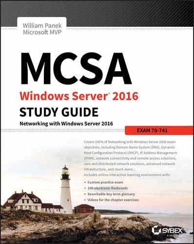
Figure 7.7 shows an example of SQL Server running on the first node of a Windows Server 2016 failover cluster.
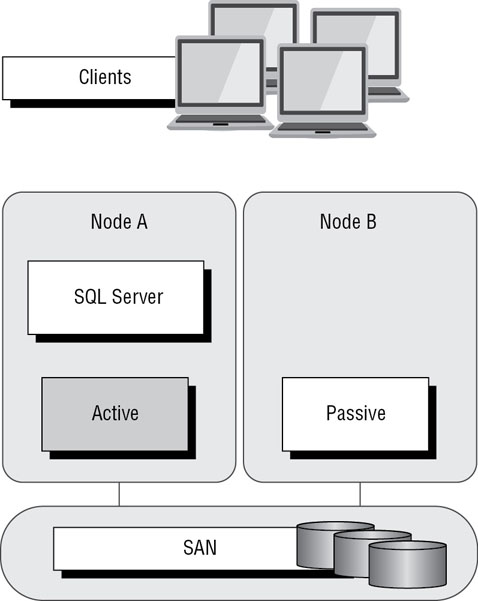
FIGURE 7.7 Using Failover Clustering to cluster SQL Server
The clustered SQL Server in Figure 7.8 can be failed over to another node in the cluster and still service database requests. However, the database will be restarted.

FIGURE 7.8 Failing the SQL Server service to another node
Failover clustering is notorious for being complicated and expensive. Windows Server 2016 makes strides in removing both of these concerns. Troubleshooting and other advanced concepts are outside of the scope of the Microsoft MCSA exams and thus this book, so I will cover only the basic requirements and concepts needed to configure a failover cluster.
Failover Clustering Requirements
The Failover Clustering feature is available in the Datacenter, Standard, and Hyper-V editions of Windows Server 2016.
To be able to configure a failover cluster, you must have the required components. A single failover cluster can have up to 64 nodes when using Windows Server 2016, however, and the clustered service or application must support that number of nodes.
To create a failover cluster, an administrator must make sure that all the hardware involved meets the cluster requirements. To be supported by Microsoft, all hardware must be certified for Windows Server 2016, and the complete failover cluster solution must pass all tests in the Validate a Configuration Wizard. Although the exact hardware will depend on the clustered application, a few requirements are standard:
- Server components must be marked with the “Certified for Windows Server 2016” logo.
- Although not explicitly required, server hardware should match and contain the same or similar components.
- All of the Validate a Configuration Wizard tests must pass.
The requirements for Failover Clustering storage have changed from previous versions of Windows. For example, Parallel SCSI is no longer a supported storage technology for any of the clustered disks. There are, however, additional requirements that need to be met for the storage components:
- Disks available for the cluster must be Fibre Channel, iSCSI, or Serial Attached SCSI.
- Each cluster node must have a dedicated network interface card for iSCSI connectivity. The network interface card you use for iSCSI should not be used for network communication.
- Multipath software must be based on Microsoft’s Multipath I/O (MPIO).
- Storage drivers must be based on storport.sys.
- Drivers and firmware for the storage controllers on each server node in the cluster should be identical.
- Storage components must be marked with the “Certified for Windows Server 2016” logo.
In addition, there are network requirements that must be met for Failover Clustering:
- Cluster nodes should be connected to multiple networks for communication redundancy.
- Network adapters should be the same make, use the same driver, and have the firmware version in each cluster node.
- Network components must be marked with the “Certified for Windows Server 2016” logo.
There are two types of network connections in a failover cluster. These should have adequate redundancy because total failure of either could cause loss of functionality of the cluster. The two types are as follows:
Public Network This is the network through which clients are able to connect to the clustered service application.
Private Network This is the network used by the nodes to communicate with each other.
To provide redundancy for these two network types, additional network adapters would need to be added to the node and configured to connect to the networks.
In previous versions of Windows Server, support was given only when the entire cluster configuration was tested and listed on the Hardware Compatibility List. The tested configuration listed the server and storage configuration down to the firmware and driver versions. This proved to be difficult and expensive from both a vendor and a consumer perspective to deploy supported Windows clusters.
When problems did arise and Microsoft support was needed, it caused undue troubleshooting complexity as well. With Windows Server 2016 Failover Clustering and simplified requirements, including the “Certified for Windows Server 2016” logo program and the Validate a Configuration Wizard, it all but eliminates the guesswork of getting the cluster components configured in a way that follows best practices and allows Microsoft support to assist you easily when needed.
Workgroup and Multi-Domain Clusters
One nice new advantage of using Windows Server 2016 is the ability to set up a cluster on systems not part of the same domain. In Window Server 2012 R2 and previous versions, clusters could only be created on machines that were part of the same domain. Windows Server 2016 allows you to set up a cluster without using Active Directory dependencies. Administrators can create clusters in the following situations:
Single-Domain Cluster All nodes in a cluster are part of the same domain.
Multi-Domain Cluster Nodes in a cluster are part of a different domain.
Workgroup Cluster Nodes are member servers and part of a workgroup.
Site-Aware, Stretched, or Geographically Dispersed Clusters (Geoclustering)
One nice advantage of Windows Server 2016 clustering is that you can set up site-aware failover clusters. Site-aware clustering allows an administrator to expand clustered nodes to different geographic locations (sites). Site-aware failover clusters allow you to set up clusters in remote locations for failover, placement policies, Cross-Site Heartbeating, and for quorum placement.
One of the issues with previous clusters was the heartbeat. The cluster heartbeat is a signal sent between servers so that they know that the machines are up and running. Servers send heartbeats and if after 5 non-responsive heartbeats, the cluster would assume that the node was offline. So if you had nodes in remote locations, the heartbeats would not get the response they needed.
But now Windows Server 2016 includes Cross-Site Heartbeating and it allows you to setup delays so that remote nodes can answer the heartbeat within time. The following two PowerShell commands allow you to setup the delay necessary for Cross-Site Heartbeating.
(Get-Cluster).CrossSiteDelay = <value>(Get-Cluster).CrossSiteThreshold = <value>
The first PowerShell command (CrossSiteDelay) is what is used to set the amount of time between each heartbeat sent to nodes. This value is done in milliseconds (default is 1000).
The second PowerShell command (CrossSiteThreshold) is the value that you set for the number of missed heartbeats (default is 20) before the node is considered offline.
One issue you may face is if you have multiple sites or if the cluster is geographically dispersed. If the failover cluster does not have a shared common disk, data replication between nodes might not pass the cluster validation “storage” tests.
Setting up a cluster in a site-aware, stretched, or geocluster (these terms can be used interchangeably) configuration is a common practice. As long as the cluster solution does not require external storage to fail over, it will not need to pass the storage test to function properly.
Cluster Quorum
When a group of people sets out to accomplish a single task or goal, a method for settling disagreements and for making decisions is required. In the case of a cluster, the goal is to provide a highly available service in spite of failures. When a problem occurs and a cluster node loses communication with the other nodes because of a network error, the functioning nodes are supposed to try to bring the redundant service back online.
How, though, is it determined which node should bring the clustered service back online? If all the nodes are functional despite the network communications issue, each one might try. Just like a group of people with their own ideas, a method must be put in place to determine which idea, or node, to grant control of the cluster. Windows Server 2016 Failover Clustering, like other clustering technologies, requires that a quorum exist between the cluster nodes before a cluster becomes available.
A quorum is a consensus of the status of each of the nodes in the cluster. Quorum must be achieved in order for a clustered application to come online by obtaining a majority of the votes available (see Figure 7.9). Windows Server 2016 has four quorum models, or methods, for determining a quorum and for adjusting the number and types of votes available:
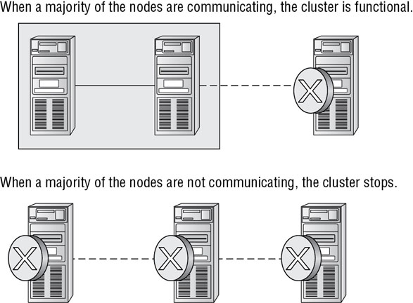
FIGURE 7.9 Majority needed
- Node majority (no witness)
- Node majority with witness (disk or file share)
- Node and file share majority
- No majority (disk witness only)
Witness Configuration
Most administrators follow some basic rules. For example, when you configure a quorum, the voting components in the cluster should be an odd number. For example, if I set up a quorum for five elements and I lose one element, I continue to work. If I lose two elements, I continue to work. If I lose three elements, the cluster stops—as soon as it hits half plus 1, the cluster stops. This works well with an odd number.
If the cluster contains an even number of voting elements, an administrator should then configure a disk witness or a file share witness. The advantage of using a witness (disk or file share) is that the cluster will continue to run even if half of the cluster nodes simultaneously go down or are disconnected. The ability to configure a disk witness is possible only if the storage vendor supports read-write access from all sites to the replicated storage.
One of the advantages of Windows Server 2016 is the advanced quorum configuration option. This option allows you to assign or remove quorum votes on a per-node basis. Administrators now have the ability to remove votes from nodes in certain configurations. For example, if your organization uses a site-aware cluster, you may choose to remove votes from the nodes in the backup site. This way, those backup nodes would not affect your quorum calculations.
There are different ways that you can setup quorum witnesses. Here are some of the options that you can choose from:
Configure a Disk Witness Choosing the quorum disk witness is normally setup if all nodes can see the disks. To set this disk witness up, the cluster must be able to see the Dedicated LUN. The LUN needs to store a copy of the cluster database and it’s most useful for clusters that are using shared storage. The following list is just some of the requirements when setting up a Disk Witness:
- LUN needs to be at least 512 MB minimum.
- The disk must be dedicated to cluster use only.
- Must pass disk storage validation tests.
- The disk can’t be used in a Cluster Shared Volume (CSV).
- You must use a single volume for Basic disks.
- No drive letter needed.
- Drive must be formatted using NTFS or ReFS.
- Can be used with hardware RAID.
- Should not be used with Antivirus or backup software
Configure a File Share Witness Administrators should choose to use the File Share Witness when you need to think about multi-site disaster recovery and the file server must be using the SMB file share.
The following list is just some of the requirements when setting up a File Share Witness:
- Minimum of 5 MB of free space required.
- File share must be dedicated to the cluster and not used to store user data or application data.
Configure a Cloud Witness Windows Server 2016 Cloud Witness is a new type of Failover Cluster quorum witness that leverages Microsoft Azure as the intercession point. The Cloud Witness gets a vote just like any other quorum witness. Administrators can setup the cloud witness as a quorum witness using the Configure a Cluster Quorum Wizard.
Dynamic Quorum Management
Another advantage in Windows Server 2016 is dynamic quorum management. Dynamic quorum management automatically manages the vote assignment to nodes. With this feature enabled, votes are automatically added or removed from nodes when that node either joins or leaves a cluster. In Windows Server 2016, dynamic quorum management is enabled by default.
Validating a Cluster Configuration
Configuring a failover cluster in Windows Server 2016 is much simpler than in previous versions of Windows Server. Before a cluster can be configured, the Validate a Configuration Wizard should be run to verify that the hardware is configured in a fashion that is supportable. Before you can run the Validate a Configuration Wizard, however, the Failover Clustering feature needs to be installed using Server Manager. The account that is used to create a cluster must have administrative rights on each of the cluster nodes and have permissions to create a cluster name object in Active Directory (if using Active Directory). Follow these steps:
- Prepare the hardware and software perquisites.
- Install the Failover Clustering feature on each server.
- Log in with the appropriate user ID and run the Validate a Configuration Wizard.
- Create a cluster.
- Install and cluster applications and services.
To install the Failover Clustering feature on a cluster node, follow the steps outlined in Exercise 7.2.
Using the Validate a Configuration Wizard before creating a cluster is highly recommended. This wizard validates that the hardware configuration and the software configuration for the potential cluster nodes are in a supported configuration. Even if the configuration passes the tests, take care to review all warnings and informational messages so that they can be addressed or documented before the cluster is created.
Running the Validate a Configuration Wizard does the following:
- Conducts four types of tests (software and hardware inventory, network, storage, and system configuration)
- Confirms that the hardware and software settings are supportable by Microsoft support staff
You should run the Validate a Configuration Wizard before creating a cluster or after making any major hardware or software changes to the cluster. Doing this will help you identify any misconfigurations that could cause problems with the failover cluster.
Running the Validate a Configuration Wizard
The Validate a Configuration Wizard, shown in Figure 7.12, is simple and straightforward to use, as its “wizard” name would suggest. It should be run after the Failover Clustering feature has been installed on each of the cluster nodes, and it can be run as many times as required.

FIGURE 7.12 The Validate a Configuration Wizard
If you already have a cluster configured and want to run the Validate a Configuration Wizard, you can do so; however, you will not be able to run all of the storage tests without taking the clustered resources offline. You will be prompted either to skip the disruptive tests or to take the clustered resources offline so that the tests can complete.
Exercise 7.3 shows the exact steps to follow to run the Validate a Configuration Wizard successfully on clusters named NODEA and NODEB, which are not yet clustered.
Addressing Problems Reported by the Validate a Configuration Wizard
After the Validate a Configuration Wizard has been run, it will show the results, as shown in Figure 7.14. This report can also be viewed in detail later using a web browser. The report is named with the date and time the wizard was run, and it is stored in %windir%clusterReports.

FIGURE 7.14 Validate a Configuration Wizard results
How should errors listed in the report be addressed? Often, the errors reported by the Validate a Configuration Wizard are self-explanatory; however, sometimes additional help is required. The following three guidelines should help troubleshoot the errors:
- Read all of the errors because multiple errors may be related.
- Use the checklists available in the Windows Server help files to ensure that all the steps have been completed.
- Contact the hardware vendor for updated drivers, firmware, and guidance for using the hardware in a cluster.
Creating a Cluster
After you have successfully validated a configuration and the cluster hardware is in a supportable state, you can create a cluster. The process for creating a cluster is straightforward and similar to the process of running the Validate a Configuration Wizard. To create a cluster with two servers, follow the instructions in Exercise 7.4.
Working with Cluster Nodes
Once a cluster is created, a couple of actions are available. First you can add another node to the cluster by using the Add Node Wizard from the Failover Cluster Management Actions pane.
At this point, you also have the option to pause a node, which prevents resources from being failed over or moved to the node. You typically would pause a node when the node is involved in maintenance or troubleshooting. After a node is paused, it must be resumed to allow resources to be run on it again.
Another action available to perform on a node at this time is evict. Eviction is an irreversible process. Once you evict the node, it must be re-added to the cluster. You would evict a node when it is damaged beyond repair or is no longer needed in the cluster. If you evict a damaged node, you can repair or rebuild it and then add it back to the cluster using the Add Node Wizard.
Clustering Roles, Services, and Applications
Once the cluster is created, applications, services, and roles can be clustered. Windows Server 2016 includes a number of built-in roles and features that can be clustered.
The following roles and features can be clustered in Windows Server 2016 (see Figure 7.15):
FIGURE 7.15 High availability roles
- DFS Namespace Server
- DHCP Server
- Distributed Transaction Coordinator (DTC)
- File Server
- Generic Application
- Generic Script
- Generic Service
- Hyper-V Replica Broker
- iSCSI Target Server
- iSNS Server
- Message Queuing
- Other Server
- Virtual Machine
In addition, other common services and applications can be clustered on Windows Server 2016 clusters:
- Enterprise database services, such as Microsoft SQL Server
- Enterprise messaging services, such as Microsoft Exchange Server
To cluster a role or feature such as Print Services, the first step is to install the role or feature on each node of the cluster. The next step is to use the Configure a Service or Application Wizard in the Failover Cluster Management tool. Exercise 7.5 shows you how to cluster the Print Services role once an appropriate disk has been presented to the cluster. To complete this exercise, you must have a cluster created.
The built-in roles and features all are configured in a similar fashion. Other applications, such as Microsoft Exchange Server 2016, have specialized cluster configuration routines that are outside the scope of this exam. Applications that are not developed to be clustered can also be clustered using the Generic Application, Generic Script, or Generic Service option in the Configure a Service or Application Wizard, as shown in Figure 7.16.

FIGURE 7.16 Configuring a generic application
Clustered Application Settings
Windows Server 2016 has options that allow an administrator to fine-tune the failover process to meet the needs of their business. These options will be covered in the next few sections.
Failover occurs when a clustered application or service moves from one node to another. The process can be triggered automatically because of a failure or server maintenance or can be done manually by an administrator. The failover process works as follows:
- The cluster service takes all of the resources in the application offline in the order set in the dependency hierarchy.
- The cluster service transfers the application to the node that is listed next on the application’s list of preferred host nodes.
- The cluster service attempts to bring all of the application’s resources online, starting at the bottom of the dependency hierarchy.
In a cluster that is hosting multiple applications, it may be important to set specific nodes to be primarily responsible for each clustered application. This can be helpful from a troubleshooting perspective since a specific node is targeted for a hosting service. To set a preferred node and an order of preference for failover, use the General tab in the Properties dialog box of the clustered application.
Also, the order of failover is set in this same dialog box by moving the order in which the nodes are listed. If NODEA should be the primary node and NODEB should be the server that the application fails to first, NODEA should be listed first and selected as the preferred owner. NODEB should be listed second, and the remaining cluster nodes should be listed after NODEB.
A number of failover settings can be configured for the clustered service. The failover settings control the number of times a clustered application can fail in a period of time before the cluster stops trying to restart it. Typically, if a clustered application fails a number of times, some sort of manual intervention will be required to return the application to a stable state.
Specifying the maximum number of failures will keep the application from trying to restart until it is manually brought back online after the problem has been resolved. This is beneficial because if the application continues to be brought online and then fails, it may show as being functional to the monitoring system, even though it continues to fail. After the application is put in a failed state, the monitoring system will not be able to contact the application and should report it as being offline.
Failback settings control whether and when a clustered application would fail back to the preferred cluster node once it becomes available. The default setting is Prevent Failback. If failback is allowed, two additional options are available, either to fail back immediately after the preferred node is available or to fail back within a specified time.
The time is specified in the 24-hour format. If you want to allow failback between 10 p.m. and 11 p.m., you would set the failback time to be between 22 and 23. Setting a failback time to off-hours is an excellent way to ensure that your clustered applications are running on the designated nodes and automatically scheduling the failover process for a time when it will impact the fewest users.
One tool that is valuable in determining how resources affect other resources is the dependency viewer. The dependency viewer visualizes the dependency hierarchy created for an application or service. Using this tool can help when troubleshooting why specific resources are causing failures and allow an administrator to visualize the current configuration better and adjust it to meet business needs. Exercise 7.6 will show you how to run the dependency viewer.
Exercise 7.6 generated a dependency report that shows how the print service is dependent on a network name and a clustered disk resource. The network name is then dependent on an IP address.
Resource Properties
Resources are physical or logical objects, such as a file share or IP address, which the failover cluster manages. They may be services or applications available to clients, or they may be part of the cluster. Resources include physical hardware devices such as disks and logical items such as network names. They are the smallest configurable unit in a cluster and can run on only a single node in a cluster at a time.
Like clustered applications, resources have a number of properties available for meeting business requirements for high availability. This section covers resource dependencies and policies.
Dependencies can be set on individual resources and control how resources are brought online and offline. Simply put, a dependent resource is brought online after the resources that it depends on, and it is taken offline before those resources. As shown in Figure 7.17, dependencies can be set on a specific resource, such as the Generic Application.

FIGURE 7.17 Resource dependencies
Resource policies are settings that control how resources respond when a failure occurs and how resources are monitored for failures. Figure 7.18 shows the Policies tab of a resource’s Properties dialog box.
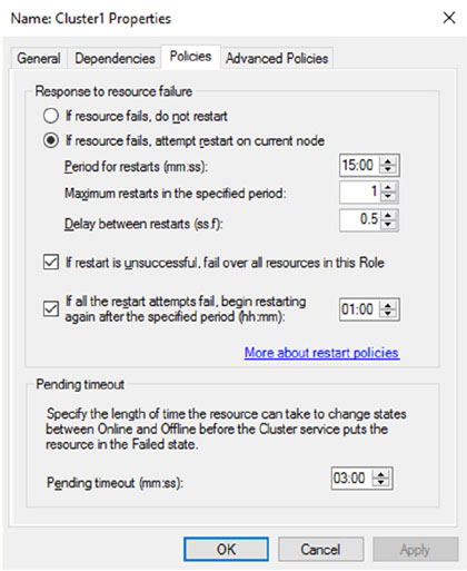
FIGURE 7.18 Resource policies
The Policies tab sets configuration options for how a resource should respond in the event of a failure. The options available are as follows:
If Resource Fails, Do Not Restart This option, as it would lead you to believe, leaves the failed resource offline.
If Resource Fails, Attempt Restart On Current Node With this option set, the resource tries to restart if it fails on the node on which it is currently running. There are two additional options if this is selected so that the number of restarts can be limited. They set the number of times the resource should restart on the current node in a specified length of time. For example, if you specify 5 for Maximum Restarts In The Specified Period and 10:00 (mm:ss) for Period For Restarts, the cluster service will try to restart the resource five times during that 10-minute period. After the fifth restart, the cluster service will no longer attempt to restart the service on the active node.
If Restart Is Unsuccessful, Fail Over All Resources In This Service Or Application If this option is selected, when the cluster service is no longer trying to restart the resource on the active node, it will fail the entire service or application to another cluster node. If you wanted to leave the application or service with a failed resource on the current node, you would clear this check box.
If All The Restart Attempts Fail, Begin Restarting Again After The Specified Period (hh:mm) If this option is selected, the cluster service will restart the resource at a specified interval if all previous attempts have failed.
Pending Timeout This option is used to set the amount of time in minutes and seconds that the cluster service should wait for this resource to respond to a change in states. If a resource takes longer than the cluster expects to change states, the cluster will mark it as having failed. If a resource consistently takes longer than this and the problem cannot be resolved, you may need to increase this value. Figure 7.19 shows the Advanced Policies tab.
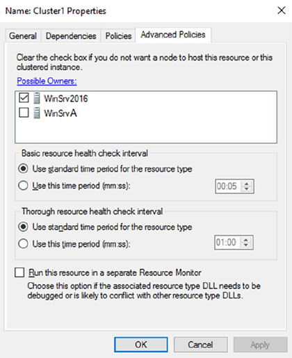
FIGURE 7.19 Resource Advanced Policies
The options available on the Advanced Policies tab are as follows:
Possible Owners This option allows an administrator to remove specific cluster nodes from running this resource. Using this option is valuable when there are issues with a resource on a particular node and the administrator wants to keep the applications from failing over to that node until the problem can be repaired.
Basic Resource Health Check Interval This option allows an administrator to customize the health check interval for this resource.
Thorough Resource Health Check Interval This option allows an administrator to customize the thorough health check interval for this resource.
Run This Resource In A Separate Resource Monitor If the resource needs to be debugged by a support engineer or if the resource conflicts with other resources, this option may need to be used.
Windows Server 2016 Clustering Features
Many new features are included in the Windows Server 2016 release for clustering. It is a rich feature set of high availability with greatly improved flexibility based on the needs of IT organizations. The new features relate to quorum behavior, virtual machine hosting, Active Directory–detached clusters, and a new dashboard.
Windows PowerShell Cmdlets for Failover Clusters As I have explained throughout this book, Windows PowerShell is a command-line shell and scripting tool. Windows Server 2016 clustering has new cmdlets that provide powerful ways to script cluster configuration and management tasks. Windows PowerShell cmdlets have now replaced the Cluster·exe command-line interface.
Cluster Shared Volumes Cluster Shared Volumes (CSV) allows for the configuration of clustered virtual machines. CSV allows you to do the following:
- Reduce the number of LUNs (disks) required for your virtual machines.
- Make better use of disk space. Any VHD file on that LUN can use the free space on a CSV volume.
- More easily track the paths to VHD files and other files used by virtual machines.
- Use a few CSV volumes to create a configuration that supports many clustered virtual machines.
CSV volumes also are utilized for the Scale-Out-File-Server cluster role.
Management of Large-Scale Clusters One advantage of Windows Server 2016 clusters is the ability for Server Manager to discover and manage the nodes in a cluster. By starting the Failover Cluster Manager from Server Manager, you can do remote multiserver management and role and feature installation. Administrators now have the ability to manage a cluster from one convenient location.
Management and Mobility of Clustered Virtual Machines Microsoft, as well as the industry as a whole, is moving toward the cloud and virtualization. With that in mind, administrators can now configure settings such as prioritizing the starting or placement of virtual machines in the clustered workloads. This allows administrators to allocate resources efficiently to your cluster.
Cluster-Aware Updating One issue that every administrator has dealt with is updating a system or application while it is running. For example, if you are running Microsoft Exchange and you want to do an Exchange update, when do you take the server offline to do the update? It always seems that someone is on the system 24 hours a day. Well, Windows Server 2016 clustering has a solution. Cluster-Aware Updating (CAU) is a new automated feature that allows system updates to be applied automatically while the cluster remains available during the entire update process.
Cluster Node Fairness Virtual Machine Load Balancing feature is new to Windows Server 2016. This new load balancing feature helps optimize the nodes in a cluster. When an organization builds a virtual machine cluster, there will be times when that cluster needs to have maintenance and certain virtual machines will be taken offline. When this happens, an unbalanced cluster (this is when some nodes are hosting VMs more often than others) may occur. This is where the VM Load Balancing feature (Node Fairness) helps the cluster. The Balancer will re-distribute VMs from an over balance node to an under balanced node. To setup Node Fairness, you would use the PowerShell command AutoBalancerLevel (shown below). The value input is a 1, 2, or 3. 1 is equivalent to the Low setting (move the host when showing more than 80% loaded), 2 is equivalent to Medium (move the host when more than 70% loaded) and 3 is equivalent to High (average nodes and move the host when showing more than 5% above the average).
(Get-Cluster).AutoBalancerLevel = <value>
Cluster Operating System Rolling Upgrade One of the problems that many IT people face is the issue with downtime while their servers get upgraded to a new operating system. Windows Server 2016 includes a new feature called Cluster Operating System Rolling Upgrade. This new feature allows an administrator to upgrade a Hyper-V or Scale-Out File Server cluster from Windows Server 2012 R2 to Windows Server 2016 without stopping the servers.
Scale-Out File Server for Application Data By utilizing Microsoft Storage Spaces, you can create a highly available clustered file share that utilizes SMB 3.0 and CSV to provide scalable access to data.
Scale-out file servers are useful for storing the following application data:
- Hyper-V virtual machine storage
- SQL Server database files
Be aware that scale-out file servers are not useful at all for typical file share data because they benefit only from applications that require a persistent connection to their storage.
Shared Virtual Hard Disks In the previous versions of Windows, Failover Cluster nodes running as virtual machines had to use iSCSI or virtual HBAs to connect directly to SAN-based storage. With Windows Server 2016, you can set your Hyper-V virtualized cluster to use a shared VHDX virtual disk. Shared virtual hard disks can reside on the following:
- A scale-out file server failover cluster
- Cluster CSV volumes
Shared virtual hard disks are extremely useful in providing highly available shared storage for the following virtualized workloads:
- SQL Server
- Virtual Machine Manager
- Exchange Server
Virtual Machine Drain on Shutdown When needing to perform maintenance on a Hyper-V failover cluster, you may have a lot of virtual machines on one node of a cluster. Inevitably, you will need to restart a cluster node for updates or shut it down for maintenance.
In previous versions of Windows, virtual machines running on the cluster would save their state, and then the cluster node would shut down. Windows Server 2016 helps alleviate this issue by automatically draining the virtual machines running on a node before it shuts down or restarts. Windows does this by attempting to live migrate all virtual machines on the cluster node to other nodes in the cluster when at all possible.
This feature is turned on by default, but it can be disabled through PowerShell.
Active Directory–Detached Clusters Previous versions of Windows Failover Clustering have depended on Active Directory to provide computer objects for the cluster name object as well as virtual computer objects. With Active Directory–detached failover clusters, communication to the cluster-form clients will use NTLM authentication rather than the normal Kerberos authentication. This is useful in maintaining high availability should a person accidently delete a virtual computer object in Active Directory that a clustered resource depends on for Kerberos authentication.
Dynamic Witness Earlier in this chapter, I mentioned the Dynamic Quorum model and how votes were dynamically adjusted based on the number of nodes in a cluster. In Windows Server 2016, there is a new feature called dynamic witness that is enabled by default when the cluster is configured to use a dynamic quorum. Since it is preferred to have an odd number of votes at any one time in a cluster, the dynamic witness will turn on or off the witness vote in order to ensure that there are an odd number of votes in the cluster.
Tie Breaker For 50% Node Split Like the dynamic witness feature just described, the Tie Breaker For 50% Node Split option in Windows Server 2016 dynamically adjusts cluster node votes in order to maintain an odd number of votes in a cluster where no witness is being used.
This is useful for a cluster in a site-aware, stretched, or geocluster configuration.
Global Update Manager Mode Since the first release of Microsoft Cluster Services appearing in Windows NT 4.0 Enterprise, all nodes in a cluster maintain a local database that keeps a copy of the cluster configuration. The Global Update Manager (GUM) is a component of the cluster that ensures that before a change is marked as being committed for the entire cluster, all nodes have received and committed that change to their local cluster database. If one or more nodes do not report back or commit a change, the cluster node is kicked out of being a member of the cluster. Another issue that can occur is that for various clustered applications, such as SQL and Exchange, their performance can be negatively impacted by the time it takes the GUM to coordinate with all the nodes of a cluster for any changes. The GUM is only as fast as the slowest node in the cluster.
With Windows Server 2016, a new feature was added to Failover Clustering called Global Update Manager mode. This feature allows you to configure the GUM read-write modes manually in order to greatly speed up the processing of changes by the GUM and to improve the performance of certain clustered resources.
Turn Off IPsec Encryption for Inter-Node Cluster Communications In network environments where IPsec is used, slow Group Policy updates and other issues can cause Active Directory Domain Services to be temporarily unavailable to cluster nodes. If the cluster intracluster communications protocol uses IPsec encryption, then these delays could cause cluster nodes to drop out of the cluster for failure to communicate in a timely manner with the rest of the nodes in the cluster. Windows Server 2016 now provides a way to turn off IPsec encryption on the cluster communication network.
Cluster Dashboard Starting with Windows Server 2012, Failover Clustering supports up to 64 nodes in a cluster. Keeping track of the status and resources on all of these nodes can be an administrative headache! Managing more than one failover cluster and determining what a certain cluster hosts can be painful as well. Fortunately, in Windows Server 2016, the Failover Cluster Manager’s main dashboard has been updated to make it easier to see the status and health of multiple clusters.
Hyper-V Replica Broker Starting with Windows Server 2012, Hyper-V supported continuous replication of virtual machines to another server or cluster for disaster recovery purposes. The Hyper-V Recovery Broker allows for virtual machines in a cluster to be replicated. The Hyper-V Recovery Broker keeps track of which cluster nodes virtual machines are residing on and ensures that replication is maintained.
Hyper-V Manager Integration into Failover Cluster Manager In Windows Server 2016, the Hyper-V Management Console is integrated with Failover Cluster Manager for managing virtual machines that are clustered. Normal Hyper-V operations such as configuring, exporting, importing, configuring replication, stopping, starting, and live migrating virtual machines are supported directly through Failover Cluster Manager.
Virtual Machine Monitoring Starting with Windows Server 2012, Failover Clustering supports Virtual Machine Monitoring for Windows Server virtual machines. Virtual Machine Monitoring monitors administrator-selected Windows services running within a virtual machine and will automatically restart a service if it should fail. If the service does not start for the configured number of restart attempts, the virtual machine will fail over to another node and then restart. For example, you can configure Failover Clustering to monitor the Print Spooler service on a Windows Server 2016 virtual machine. If the Print Spooler service goes offline, then the cluster will attempt to restart the Print Spooler service within the virtual machine. If the service still fails, Failover Clustering will move the virtual machine to another node.
PowerShell Commands for Clustering
The following table (Table 7.3) is just some of the PowerShell commands that you can use to configure and manage Windows Server 2016 clustering.
TABLE 7.3 Clustering PowerShell Commands
| PowerShell Command | Description |
| Add-ClusterDisk | This command allows an admin to add a new disk to a failover cluster. The disk’s logical unit number (LUN) must be visible to all cluster nodes. |
| Add-ClusterFileServerRole | This command allows an admin to create a clustered file server. |
| Add-ClusterGenericApplicationRole | This command allows you to configure high availability for an application that is normally not designed for clustering. |
| Add-ClusterGroup | This command allows an admin to add a resource group to the failover cluster. |
| Add-ClusterNode | This command allows an admin to add a node to a failover cluster. |
| Add-ClusterResource | This command allows an admin to add a resource to a failover cluster. |
| Add-ClusterResourceDependency | This command allows an admin to add a resource dependency to a failover cluster. |
| Add-ClusterServerRole | This command allows you to add the cluster server role to a server. |
| Block-ClusterAccess | This command allows an admin to block the specified users from accessing a cluster. |
| Get-Cluster | This command shows you the information about a failover clusters. |
| Get-ClusterAccess | This command shows you the permissions for a failover clusters. |
| Get-ClusterNode | This command shows you the information about the servers in a failover clusters. |
| Get-ClusterQuorum | This command shows you the information about the cluster quorum in a clusters. |
| New-Cluster | This command allows you to create a new failover cluster. |
| Remove-Cluster | This command allows you to remove a failover cluster. |
| Remove-ClusterAccess | This command allows an admin to remove a user’s access from the cluster. |
| Remove-ClusterNode | This command allows you to remove a node from a failover cluster. |
| Start-Cluster | This command allows an admin to start the Cluster service on all nodes. |
| Stop-Cluster | This command allows an admin to stop the Cluster service on all nodes. |
| Stop-ClusterNode | This command stops the Cluster service on a node. |
| Test-Cluster | This command allows an admin to complete validation tests for a cluster. |
Implementing Storage Spaces Direct
Storage Spaces Direct uses local-attached drives on servers to create highly available storage at a minimal cost of traditional storage devices (SAN or NAS). Storage Spaces Direct uses regular hard drives that are connected to a single node of the failover cluster and these disks can be used as storage for the cluster.
To understand how Storage Spaces Direct truly works, I think it is better to first understand some other technology terms for Windows Server 2016. When an IT administrator takes a bunch of physical disks and puts them together it is called a storage pool. Storage spaces are virtual disks that are created from storage pools. Storage Spaces Direct is the evolution of Storage Spaces.
Many of the same features are used in Windows Server 2016 like Failover Clustering, Cluster Shared Volumes, and SMB.
Storage Spaces Direct utilizes disks that are connected to one node of a failover cluster and allows for the creation of pools using those disks by Storage Spaces. Storage Spaces Direct streamlines deployment by using converged or hyper-converged architecture.
Virtual Disks (Spaces) that are constructed on a pool will have their mirrors or parity (redundant data) span across the disks using different nodes of the cluster. Since replicas of the data are spread across the disks, this allows for access to data in the event a node fails or is going down for maintenance.
You can implement Storage Spaces Direct in virtual machines with each VM configured with two or more virtual disks connected to the VM’s SCSI Controller. Each node of the cluster running inside the virtual machine can connect to its own disks, but utilizing Storage Spaces Direct allows all the disks to be part of the Storage Pool that spans the entire cluster node.
For the redundant data (mirror or parity spaces) to be spread across the nodes, Storage Spaces Direct uses SMB3 as the protocol transport.
Networking Hardware To communicate between servers Storage Spaces Direct uses SMB3, including SMB Direct and SMB Multichannel over Ethernet. It is recommended to use 10+Gbe with Remote-Direct Memory Access (RDMA), or either Internet Wide Area RDMA Protocol (iWARP) or RDMA over Converged Ethernet (RoCE).
Storage Hardware
- 2 – 16 servers with locally-attached SATA, SAS, or NVMe (non-volatile memory express) drives
- Must have at least 2 solid-state drives on each server and at least 4 additional drives.
- SATA and SAS device should be following a Host-Bus Adapter (HBA) and SAS expander.
Failover Clustering To connect the servers, Windows Server 2016 uses the built-in clustering feature.
Software Storage Bus Storage Spaces Direct has a new feature called Software Storage Bus. This allows all the servers to see all of each other’s local drives by spanning the cluster and establishing a software-defined storage structure.
Storage Bus Layer Cache The Software Storage Bus joins the fastest drives available to the slower drives to provide server-side read/write caching that speeds up the IO and boosts data.
Storage Pool The storage pool is the collection of drives that form the Storage Space. It is created automatically and all qualified drives are discovered and added. It is recommended that an administrator use the default settings on one pool per cluster.
Storage Spaces Storage Spaces offers fault tolerance to a virtual disk using mirroring, erasure coding, or both. It is thought of as distributed, software-defined RAID utilizing the drives in the pool. These virtual disks normally have resiliency when two synchronized drives or servers fail.
Resilient File System (ReFS) The Resilient File System (ReFS) is Microsoft’s latest file system which was designed to maximize data availability, efficiently scale to large data sets across varied workloads, and provide data integrity. It includes hastening the .vhdx file operations such as creating, expanding, checkpoint merging, and built-in checksums to distinguish and fix bit errors. ReFS also introduced real-time tiers, based on usage, which will rotate data between “hot” and “cold” storage-tiers.
Cluster Shared Volumes The Cluster Shared Volumes (CSV) file system unites all the ReFS volumes into a single namespace available through any server. This namespace allows every server and every volume to look and act like it’s mounted locally.
Scale-Out File Server In converged deployments only is this necessary. It offers remote file access by using the SMB3 protocol to clients over the network. This essentially turns Storage Spaces Direct into Network-Attached Storage (NAS).
The Benefits of Storage Spaces Direct
The following are just some of the benefits of using Storage Spaces Direct with Windows Server 2016:
Simplicity In less than 15 minutes, an administrator can go from a standard server running Windows Server 2016 to creating a Storage Spaces Direct cluster. It’s just the click of a check box if an administrator is using System Center.
Unrivaled Performance Storage Spaces Direct exceeds 150,000 mixed 4k random IOPS per server with reliability, low latency, built-in read/write cache, and support for NVMe drives that are mounted directly on the PCIe bus.
Fault Tolerance Constantly available built-in resiliency that will handle drives, servers, or component failures. Chassis and rack fault tolerance can also be configured for larger deployments. There are no complex management steps needed when hardware fails. Simply change it out for another one and the software will fix itself.
Resource Efficiency Greater resource efficiency with Erasure coding delivering up to 2.4x more storage. Using Local Reconstruction Codes and ReFS, real-time tiers extend to hard disk drives and mixed hot/cold workloads, all while reducing CPU usage to give the resources back to the virtual machines where they are needed.
Manageability Keep excessively active virtual machines in order by using Storage QoS Controls with minimum and maximum per-VM IOPS limits. Continuously monitor and alert by using the built-in Health Service. There are also new APIs that make it easier to collect cluster-wide performance statistics and capacity metrics.
Scalability For multiple petabytes of storage per cluster, an administrator can increase up to 16 servers and add over 400 drives. To scale out, an administrator will just need to add drives or add more servers. Storage Spaces Direct will automatically add the new drives and begin to utilize them.
Deployment Options
When using Windows Server 2016 and installing Storage Spaces Direct, there are two deployment options that you can choose from:
Converged
In converged, there are separate clusters for each storage and compute. The converged deployment option, also called “disaggregated,” puts a Scale-Out File Server (SoFS) on top of Storage Spaces Direct to provide Network-Attached Storage (NAS) over SMB3 file shares. This allows for scaling computer/workloads separately from the storage cluster. This is essential when working with large-scale deployments such as Hyper-V Infrastructure as a Service (IaaS).
Hyper-Converged
In hyper-converged, there is only one cluster for storage and compute. The hyper-converged deployment option runs the Hyper-V virtual machines or SQL Server databases directly on the servers delivering the storage, storing files all on the local volumes. This removes the need to configure file server access and permissions. It also reduces the hardware costs associated for small-to-medium business or remote office/branch office deployments.
Requirements to Setup Storage Spaces Direct
To setup Storage Spaces Direct properly, you must make sure that all of your hardware components meet the minimum requirements. Table 7.4 was taken directly from Microsoft’s website for the requirements needed and also what is actually recommended by Microsoft for proper configuration of Storage Spaces Direct.
TABLE 7.4 Storage Space Direct Requirements
| Component | Requirements |
| Servers | Minimum of 2 servers, maximum of 16 servers All servers should be the same make and model. |
| CPU | Minimum of Intel Nehalem or later compatible processor |
| Memory | 4 GB of RAM per terabyte (TB) of cache drive capacity on each server, to store Storage Spaces Direct metadata. Any memory used by Windows Server, VMs, and other apps or workloads. |
| Networking | Minimum of 10 Gbps network interface for intra-cluster communication. Recommended: Two NICs for redundancy and performance Recommended: NICS that are remote-direct memory access (RDMA) capable, iWARP or RoCE |
| Drives | Use local-attached SATA, SAS, or NVMe drives. Every drive must be physically connected to only one server. All servers must have the same drive types. Recommended: All servers have the same drive configuration. SSDs must have power-loss protection, i.e. they are “enterprise-grade.” Recommended: SSDs used for cache have high endurance, providing a minimum of 5 drive-writes-per-day (DWPD). Add capacity drives in multiples of the number of NVMe or SSD cache devices. Not supported: Multi-path IO (MPIO) or physically connecting drives via multiple paths. |
| Host-bus adapter (HBA) | Simple pass-through SAS HBA for both SAS and SATA drives. SCSI Enclosure Services (SES) for SAS and SATA drives. Any direct-attached storage enclosures must present Unique ID. Not Supported: RAID HBA controllers or SAN (Fibre Channel, iSCSI, FCoE) devices. |
Storage Spaces Direct Using Windows PowerShell
The following table (Table 7.5) is just some of the PowerShell commands that you can use to configure and manage Storage Spaces Direct.
TABLE 7.5 Storage Spaces Direct PowerShell commands
| PowerShell Command | Description |
| Disable-NetQosFlowControl | This command allows an administrator to turn off flow control. |
| Enable-ClusterStorageSpacesDirect | This command enables Storage Spaces Direct. |
| Enable-NetAdapterQos | This command allows an administrator to apply network QoS policies to the target adapters. |
| Enable-NetAdapterRDMA | This command allows an administrator to enable remote direct memory access (RDMA) on a network adapter. |
| Enable-NetQosFlowControl | This command allows an administrator to turn on flow control. |
| Get-NetAdapter | This command will retrieve a list of the network adapters. |
| Get-StoragePool | This command allows you to see a specific storage pool, or a set of StoragePool objects. |
| Get-StorageTier | This command allows you to see storage tiers on Windows Storage subsystems. Use this command to see Storage Spaces Direct default tier templates called Performance and Capacity. |
| New-Cluster | This command creates a new cluster. |
| New-NetQosPolicy | This command allows an admin to create a new network QoS policy. |
| New-NetQosTrafficClass | This command allows you to create a traffic class (like SMB). |
| New-Volume | This command creates a new volume. |
| Set-Item | This command allows an administrator to configure the trusted hosts to all hosts. |
| Test-Cluster | This command allows an administrator to test a set of servers for use as a Storage Spaces Direct cluster. |
| Update-StorageProviderCache | This command allows you to update the cache of the service for a particular provider and associated child objects. |
Achieving High Availability with Hyper-V
One of the nice advantages of using Hyper-V is the ability to run an operating server within another server. Virtualization allows you to run multiple servers on top of a single Hyper-V server. But we need to make sure that these servers stay up and running.
That is where Hyper-V high availability comes into play. Having the ability to ensure that your Hyper-V servers are going to continue to run even if there is a hardware issue is an important step in guaranteeing the success of your network.
There are many ways that you can ensure that your virtual machines will continue to operate. One is to set up clustering and another is to set up Hyper-V high availability without clustering.
To set up reliability without clustering requires that your Hyper-V servers have replica copies that can automatically start up if the virtual machine errors out. This is referred to as Live Migration and replica servers.
Implementing a Hyper-V Replica
Hyper-V Replica is an important part of the Hyper-V role. It replicates the Hyper-V virtual machines from the primary site to the replica secondary sites simultaneously.
Once an administrator enables Hyper-V Replica for a particular virtual machine on the primary Hyper-V host server, the Hyper-V replica will begin to create an exact copy of the virtual machine for the secondary site. After this replication, Hyper-V Replica creates a log file for the virtual machine VHDs. This log file is rerun in reverse order to the replica VHD. This is done using replication frequency. The log files and reverse order helps ensure that the latest changes are stored and copied asynchronously. If there is an issue with the replication frequency, then the administrator will receive an alert.
On the virtual machine, an administrator can establish resynchronization settings. This can be setup to be done manually, automatically, or automatically on an explicit schedule. To fix constant synchronization issues an administrator may choose to set up automatic resynchronization.
Hyper-V Replica will aid in a disaster recovery strategy by replicating virtual machines from one host to another while keeping workloads accessible. Hyper-V Replica can create a copy of a running virtual machine to a replica offline virtual machine.
Hyper-V Hosts
With replication over a WAN link the primary and secondary host servers can be located in the same physical location or at different geographical locations. Hyper-V hosts can be standalone, clustered, or a combination of both. Hyper-V Hosts are not dependent upon Active Directory and there is no need to be domain members.
Replication and Change Tracking
When an administrator enables Hyper-V Replica on a particular virtual machine an identical copy of the virtual machine is created on a secondary host server. Once this happens, the Hyper-V Replica will create a log file that will track changes made on a virtual machine VHD. The log file is rerun in reverse order to the replica VHD. This is based on the replication frequency settings. This ensures that the latest changes are created and replicated asynchronously. This can be done over HTTP or HTTPS.
Extended (Chained) Replication
Extended (chained) Replication allows an administrator to replicate a virtual machine from a primary host to a secondary host and then replicate the secondary host to a third host. It is not possible to replicate from the primary host directly to the second and third hosts.
Extended (Chained) Replication aids in disaster recovery in that an administrator can recover from both the primary and extended replica. Extended Replication will also aid if the primary and secondary locations go offline. It must be noted that the extended replica does not support application-consistent replication and it must use the same VHD that the secondary replica uses.
Failover
If the primary or the secondary (extended) host server locations go offline, an administrator can manually initiate failover. Failover is not automatic. There are several different types of manually initiating failover:
Test Failover Use Test Failover to verify that the replica virtual machine can successfully start in the secondary site. It will create a copy test virtual machine during failover and does not affect standard replication. After the test failover, if the administrator selects Failover on the replica test virtual machine the test failover will be deleted.
Planned Failover Use Planned Failover during scheduled downtime. The administrator will have to turn off the primary machine before performing a planned failover. Once the machine fails over, the Hyper-V Replica will start replicating changes back to the primary server. The changes are tracked and sent to ensure that there is no data lost. Once the planned failover is complete, the reverse replication begins so that the primary virtual machine becomes the secondary and vice versa. This ensures that the hosts are synchronized.
Unplanned Failover Use Unplanned Failover during unforeseen outages. Unplanned failover is started on the replica virtual machine. This should only be used if the primary machine goes offline. A check will confirm whether the primary machine is running. If the administrator has recovery history enabled, then it is possible to recover to an earlier point in time. During failover an administrator should ensure that the recovery point is acceptable and then finish the failover to ensure that recovery points are combined.
Virtual Machine Advanced Features
One nice feature of virtual machines is the ability to setup advanced features. In the Advanced Features section (see Figure 7.20), there are multiple settings that you can configure.
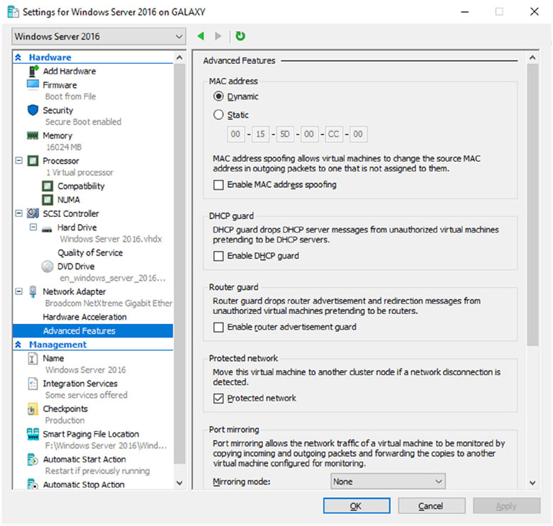
FIGURE 7.20 VM Advanced Features
MAC Addressing
The first thing that you can configure in the Advanced Features section is setting a MAC address. The MAC address is a physical address that is associated to the NIC adapter. Administrators have the ability to set the MAC address to Dynamic (creates its own MAC addresses) or Static (this is where you can set a MAC address).
You also have the ability to do MAC spoofing. This is where a VM can change the source MAC address in outgoing packets to one that is not assigned to the NIC adapters.
DHCP Guard
DHCP guard drops DHCP server messages from unauthorized virtual machines pretending to be a DHCP server. So what does this mean to you? If a server tries to pretend to be a DHCP server, your virtual machine will drop any messages that are sent by that DHCP server.
Router Guard
Router guard drops router advertisement and redirection messages from unauthorized virtual machines pretending to be routers. It almost works the same way DHCP guard works. If an unauthorized router tries to send messages to a virtual machine, that VM will not accept those messages.
Protected Network
Administrators have the ability to set Network Health Detection at the virtual machine level for a Hyper-V host cluster. This is configured as a Protected Network. By setting the Protected Network checkbox, the virtual machine will be moved to another cluster node if a network disconnection is detected. If the health of a network connection is showing as disconnected, the VM will be automatically moved.
Port Mirroring
Port mirroring allows the network traffic of a virtual machine to be monitored by copying incoming and outgoing packets and forwarding the copies to another virtual machine configured for monitoring.
Single Root I/O Virtualization
The single root I/O virtualization (SR-IOV) interface is a continuation of the PCI Express (PCIe) interface specification. SR-IOV allows a device (like a network adapter) to separate its resources between multiple PCIe hardware functions.
Device Naming
Device naming causes the name of the network adapter to be propagated into supported guest operating systems.
NIC Teaming
NIC Teaming, also known as load balancing and failover (LBFO), gives an administrator the ability to allow multiple network adapters on a system to be placed into a team. Independent hardware vendors (IHVs) have required NIC Teaming, but until Windows Server 2012, NIC Teaming was not part of the Windows Server operating system.
To be able to use NIC Teaming, the computer system must have at least one Ethernet adapter. If you want to provide fault protection, an administrator must have a minimum of two Ethernet adapters. One advantage of Windows Server 2016 is that an administrator can set up 32 network adapters in a NIC team.
NIC Teaming is a common practice when setting up virtualization. This is one way that you can have load balancing with Hyper-V.
NIC Teaming gives an administrator the ability to allow a virtual machine to use virtual network adapters in Hyper-V. The advantage of using NIC Teaming in Hyper-V is that the administrator can use NIC Teaming to connect to more than one Hyper-V switch. This allows Hyper-V still to have connectivity even if the network adapter under the Hyper-V switch gets disconnected.
An administrator can configure NIC Teaming in either Server Manager or PowerShell. NIC teaming can be configured in different configuration models including Switch Independent or Switch Dependent. Switch Independent means that each NIC adapter is connected into a different switch. Switch Dependent means that all NIC adapters are connected into the same switch. If you use Switch Independent NIC Teaming, then you must connect your NICs to different switches, but both switches must be on the same subnet.
Remote Direct Memory Access
When most of us think of Hyper-V, we think of a group of virtual machines sharing access to a systems resource. With Windows Server 2016, Hyper-V includes Remote Direct Memory Access (RDMA).
RDMA allows one computer to directly access memory from the memory of another computer without the need of interfacing with either one’s operating system. This gives systems the ability to have high throughput and low-latency networking. This is very useful when it comes to clustering systems (including Hyper-V).
Windows Server 2012 R2 RDMA services couldn’t be bound to a Hyper-V Virtual Switch and because of this, Remote Direct Memory Access and Hyper-V had to be on the same computer as the network adapters. Because of this, there was a need for a higher number of physical network adapters that were required to be installed on the Hyper-V host.
Because of the improvements of RDMA on Windows Server 2016, administrators can use less network adapters while using RDMA.
Switch Embedded Teaming
Earlier we discussed NIC Teaming but we also have the ability to do Switch Embedded Teaming (SET). SET can be an alternative to using NIC Teaming in environments that include Hyper-V and the Software Defined Networking (SDN) stack in Windows Server 2016.
SET does use some of the functionality of NIC Teaming in the Hyper-V Virtual Switch, but SET allows an administrator to combine a group of physical adapters (minimum of 1 adapter and a maximum of 8 adapters) into software based virtual adapters.
By using virtual adapters, you get better performance and greater fault tolerance in the event of a network adapter going bad. For SET to be enabled, all of the physical network adapters must be installed on the same physical Hyper-V host.
One of the requirements of SET is that all network adapters that are members of the SET group be identical adapters. This means that they need to be the same adapter types from the same manufacturer.
One main difference between NIC Teaming and Set is that SET only supports Switch Independent mode setups. Again this means that the NIC adapters are connected to different switches.
Administrators need to create a SET team at the same time that they create the Hyper-V Virtual Switch. Administrators can do this by using the Windows PowerShell command New-VMSwitch.
At the time an administrator creates a Hyper-V Virtual Switch, the administrator needs to include the EnableEmbeddedTeaming parameter in their command syntax. The following example shows a Hyper-V switch named StormSwitch:
New-VMSwitch -Name StormSwitch -NetAdapterName "NIC 1","NIC 2" -EnableEmbeddedTeaming $true
Administrators also have the ability to remove a SET team by using the following PowerShell command. This example removes a Virtual Switch named StormSwitch.
Remove-VMSwitch "StormSwitch
Virtual Machine Queue
Windows Server 2016 Hyper-V includes a feature called Virtual machine queue (VMQ) as long as the hardware is VMQ compatible network hardware. VMQ uses packet filtering to provide data from an external virtual machine network directly to virtual machines. This helps reduce the overhead of routing packets from the management operating system to the virtual machine.
Once VMQ is enabled on Hyper-V, a dedicated queue is created on the physical network adapter for each virtual network adapter to use. When data arrives for the virtual network adapter, the physical network adapter places that data in a queue and once the system is available, all of the data in the queue is delivered to the virtual network adapter.
To enable the virtual machine queue on a specific virtual machine, enter the settings for the virtual machine and expand Network Adapter. Click on Hardware Acceleration and on the right hand window; check the box for Enable virtual machine queue.
To enable VMQ on a physical network adapter:
- Open Device Manager.
- Expand the Network adapters section and right-click the name of the network adapter. Choose Properties.
- On the Advanced tab in the properties, locate the setting for virtual machine queues and make sure it is enabled. If the setting is not available, the adapter does not support VMQ.
Receive Side Scaling
Receive Side Scaling (RSS) allows a system’s network adapter to spread the network processing between multiple processor cores in systems that have a multi-core processor. Due to the fact that RSS can distribute the networking load across multiple processors, the system can handle more network traffic.
RSS has the ability to work with systems that have more than sixty four (64) processors. RSS can do this because it spreads the load across all of the processors. Because RSS can spread the network load, you end up with TCP load balancing. RSS also has the ability to load balance non-TCP traffic like UDP and multicast messages. RSS also allows an administrator to have better auditing and management capabilities.
With the release of Windows Server 2012, RSS started working with load balancing across Non-Uniform Memory Access (NUMA) systems. RSS also includes some of the following capabilities:
- Event tracing for RSS logs
- RSS configuration information
- Windows Management Instrumentation (WMI) for RSS
- PowerShell for RSS
- Dynamic load balancing
- RSS profiles
- Benefits for working with low latency
If you want to enable or disable RSS, you would complete the following steps.
- Open an elevated Command prompt by right clicking Command Prompt, and then choosing Run as administrator.
-
At the Command Prompt, type the following command and hit Enter.
netsh interface tcp set global rss=enabled
- Close the Command Prompt window.
- Open Device Manager (right click Start and then click Device Manager).
- Expand Network adapters, right-click the network adapter you want to work with, and then click Properties.
- In the network adapter properties, click on the Advanced tab. On the Receive-side scaling setting, make sure it is enabled or disabled (depending on what you need to do).
Virtual Receive-Side Scaling
Virtual Receive-side scaling (VRSS) is the virtual equivalent of RSS. VRSS is a Windows Server 2016 feature that allows a virtual network adapter to distribute the load across multiple virtual processors in a virtual machine.
VRSS works with many different types of technologies including:
- IPv4 and IPv6
- TCP and UDP
- LBFO (NIC Teaming)
- Live Migration
- Network Virtualization using Generic Routing Encapsulation (NVGRE)
VRSS is not enabled by default. VRSS is easily enabled or disabled inside of the virtual machine or on a physical host by using PowerShell cmdlets. If you are going to enable VRSS in a virtual machine, the Windows operating system of the virtual machine must be one of the following:
- Windows 8.1
- Windows 8.1 with integration components installed.
- Windows 10
- Windows Server 2012 R2
- Windows Server 2012 R2 with integration components installed.
- Windows Server 2016.
To enable VRSS using PowerShell, you would need to run one of the following commands from PowerShell. Either PowerShell command will enable VRSS.
Enable-NetAdapterRSS -Name "AdapterName"Set-NetAdapterRSS -Name "AdapterName" -Enabled $True
To disable VRSS using PowerShell, you would need to run one of the following commands from PowerShell. Either PowerShell command will disable VRSS.
Disable-NetAdapterRSS -Name "AdapterName"Set-NetAdapterRSS -Name "AdapterName" -Enabled $False
Virtual Machine Multi-Queue
Windows Server 2016 Hyper-V includes a new feature called Virtual Machine Multi-Queue (VMMQ). VMMQ was created using previous versions of RSS and VMQ.
Today’s network adapters have more queues than the virtual machines they work with. In previous versions of virtualization (before Windows Server 2012 R2) a single virtual machine could be assigned to a single virtual machine queue. This single queue would have a set affinity to a single processor. So what this means is that even though network adapters can handle multiple queues, the virtual machines could only send traffic using a single queue.
VMMQ helps resolve this issue. VMMQ allocates multiple queues to a single virtual machine and each queue will have its own affinity settings to a core. For this to operate properly, the virtual machine must have the ability to work with multiple virtual CPUs (vCPUs).
Virtual Machine Quality of Service
There may be times when you want to control the traffic that is generated by a virtual machine. Virtual Machine Quality of Service (vmQoS) is a Hyper-V features that does just that.
Virtual Machine Quality of Service allows an administrator to set the bandwidth limits generated by a virtual machine. Administrators can also use vmQoS to set a bandwidth reserve on an external network connection. This helps stop a single virtual machine from chocking the bandwidth of another virtual machine. Administrators have the ability to set minimum and maximum bandwidth limits.
Administrators that have the ability to set performance levels can use these features when service level agreements (SLAs) need to be enforced between your organization and your clients. This allows you to guarantee certain bandwidth levels for your customers and it makes sure that no other customer’s bandwidth is compromised. Hyper-V QoS gives an administrator the ability to:
- Enforce minimum and maximum bandwidth limits for traffic flow. This is identified with a port number in the Hyper-V Virtual Switch.
- Configure Hyper-V virtual switch port minimum and maximum bandwidth by using either PowerShell cmdlets or Windows Management Instrumentation (WMI).
- Configure multiple Hyper-V virtual network adapters and specify the QoS on each virtual network adapter independently.
Windows Server 2016 Hyper-V QoS also allows an administrator to use compatible hardware for Data Center Bridging (DCB).
DCB is a suite of Institute of Electrical and Electronics Engineers (IEEE) standards that allow multiple infrastructure technologies (i.e. storage, data networking, Inter-Process Communication (IPC), and management traffic) to all share the same Ethernet network infrastructure. To enable DCB, you would use the following PowerShell cmdlet:
Install-WindowsFeature -Name Data-Center-Bridging -IncludeManagementTools
By using DCB, administrators can unite multiple types of network traffic onto a single network adapter. This allows administrators to have a guaranteed level of service for every type of network traffic.
To enable the vmQoS features, an administrator can use Windows PowerShell. Administrators can configure these features manually or by writing a script to automate the installation.
VM Checkpoints
One thing that you may want to setup on your Hyper-V server is recovery points or checkpoints. A checkpoint is a snap shot in time from when an administrator can recover a virtual machine. It’s like taking a picture of the virtual machine and using that picture to recover the VM. Administrators can create multiple checkpoints of a VM and then recover back to any of those checkpoints if there is an issue. Using a more recent recovery point will result in less data lost. Checkpoints can be accessed from up to 24 hours ago.
If you want to enable these checkpoints in time for Hyper-V, you just need to follow the steps below:
- In Hyper-V Manager, right-click on the virtual machine and then click Settings.
- Under the Management section, choose Checkpoints.
- To enable checkpoints for a VM, check the box Enable checkpoints. If you want to disable checkpoints, just clear the box.
- Once finished, Click Apply. Once you are finished, click OK and close the Hyper-V Manager.
Understanding Live Migration
Before we can implement Live Migration, first you need to understand what Live Migration does for Hyper-V. Hyper-V live migration transfers a running virtual machine from one physical server to another. The real nice advantage of Live Migration is that during the move of the virtual machine, there is no impact on the network’s users. The virtual machine will continue to operate even during the move. This is different from using Quick Migrations. Quick Migrations require a pause in the Hyper-V VM while it’s being moved.
Live Migrations allow administrators to move virtual machines between servers. This is very useful when a Hyper-V server starts having issues. For example, if a Hyper-V machine is starting to have hardware issues, you can move the virtual machines from that Hyper-V server to another server that is running properly.
When setting up VM migrations, you have a few options. You can Live Migrate a VM, Quick Migrate a VM, or just move a VM. As stated before, Live Migration requires no interruption of the VM. Quick Migration requires that you first pause the VM, then save the VM, then move the VM and finally re-start the VM. Moving a virtual machine means that you are going to copy a VM from one Hyper-V server to another while the virtual machine is turned off.
So if you decide to setup and use Live Migrations, there are a few things that you should understand before setting it up. So let’s take a look at some of the configuration settings that you can configure.
Configure CredSSP or Kerberos authentication
When choosing to setup Live Migrations, one of the settings that you get to manipulate is the type of authentication you can use. Choosing the authentication type is a feature listed under the Advanced Features of Live Migration. Administrators can choose two types of authentication (as shown in Figure 7.21): Kerberos or Credential Security Support Provider (CredSSP).

FIGURE 7.21 Live Migration Advanced Features
Authentication is choosing which protocol you will use to guarantee that live migration traffic between the source and destination servers are verified. Let’s take a look at both options.
- Use Credential Security Support Provider (CredSSP):
- This option allows an administrator to setup better security but requires constrained delegation for Live Migration. Administrators have the ability to sign in to the source server. Administrators can sign in to the source server by using a local console session, a Remote Desktop session, or a remote Windows PowerShell session.
- Use Kerberos:
- This option allows an administrator to avoid having to sign in to the server, but requires constrained delegation to be set up.
Another section that you setup in the Advanced Features of Live Migrations is the Performance options. This section allows you to choose how the network traffic for Live Migrations will be configured. There are three options that you can choose from:
TCP/IP The memory of the virtual machine being migrated is copied over the network to the destination server over a TCP/IP connection.
Compression The memory of the virtual machine being migrated is compressed and then copied over the network to the destination server over a TCP/IP connection.
SMB The memory of the virtual machine is copied over the network to the destination server over a SMB (Server Message Block) connection. SMB Direct will be used if the network adapters of both the source and destination server have Remote Direct Memory Access (RDMA) capabilities enabled.
Implementing Live Migration
You will need the following to set up non-clustered hosts for live migration:
- A user account in the local Hyper-V Administrators group or the Administrators group on both the source and destination computers. Membership in the Domain Administrators group (if using a domain).
- The Hyper-V role in Windows Server 2016 or Windows Server 2012 R2 installed on both the source and destination servers. Live migration can be done if the virtual machine is at least version 5.
- The source and destination computers must belong to the same Workgroup or Active Directory domain or belong to trusted domains.
- The Hyper-V management tools installed on the server. Computer must be running Windows Server 2016 or Windows 10.
If an administrator wants to setup the source and destination of the live migration, they would need to use the following steps in Hyper-V Manager:
- Open Hyper-V Manager. (Click Start ➢ Administrative Tools ➢ Hyper-V Manager.)
- In the navigation pane, click on one of the servers. Right click on the server ➢ Hyper-V Settings ➢ Live Migrations.
- Click on the Live Migrations pane. Check the box Enable incoming and outgoing live migrations.
- Under the section Simultaneous live migrations, specify the number of Simultaneous live migrations (the default is 2).
- Under Incoming live migrations, administrators can choose to accept any network for live migrations or specifically the IP address you want to use for live migration. If you want to use an IP address, click the Add button and type in the IP address information. Click OK once you’re finished.
- For Kerberos and performance options, expand Live Migrations (click the plus sign next to Live Migrations) and then select Advanced Features.
- Under Authentication protocol, select either Use CredSSP or Use Kerberos.
- Under Performance options, Select performance configuration options (either TCP/IP, Compression, or SMB).
- Click OK.
- If you have any other servers that you want to setup for Live Migrations, select the server and repeat the steps.
Implement Shared Nothing Live Migration
Administrators can now Live Migrate virtual machines even if the Hyper-V host is not part of a cluster. Before using Live Migrate without a Windows Cluster an administrator will need to configure the servers. Either choose Kerberos or Credential Security Support Provider (CredSSP) to authenticate the Live Migration.
To trigger a Shared Nothing Live Migration remotely, the administrator will need to enable Kerberos constrained delegation.
Constrained delegation is configured through Active Directory Users and Computers in the Delegation tab for each computer taking part in the Shared Nothing Live Migration.
Implementing Storage Migration
Hyper-V supports moving virtual machine storage without downtime by allowing the administrator to move storage while the virtual machine is running. This can be performed by using Hyper-V Manager or Windows PowerShell.
An administrator can add storage to a Hyper-V cluster or a standalone computer, and then move virtual machines to the new storage while the virtual machines continue to run.
An administrator can move virtual machine storage between physical storage devices to respond to a decrease in performance that results from bottlenecks.
Storage Migration Requirements
The following will be needed to utilize Hyper-V functionality of moving virtual machine storage:
- One or more installations of Windows Server 2016 with the Hyper-V role installed.
- A server that is capable of running Hyper-V.
- Virtual machines that are configured to use only virtual hard disks for storage.
Storage Migration allows administrators to move the virtual hard disks of a virtual machine while the virtual hard disks are still able to be used by the running virtual machine (see Figure 7.22). When an administrator moves a running virtual machine’s virtual hard disks, Hyper-V performs the following steps:
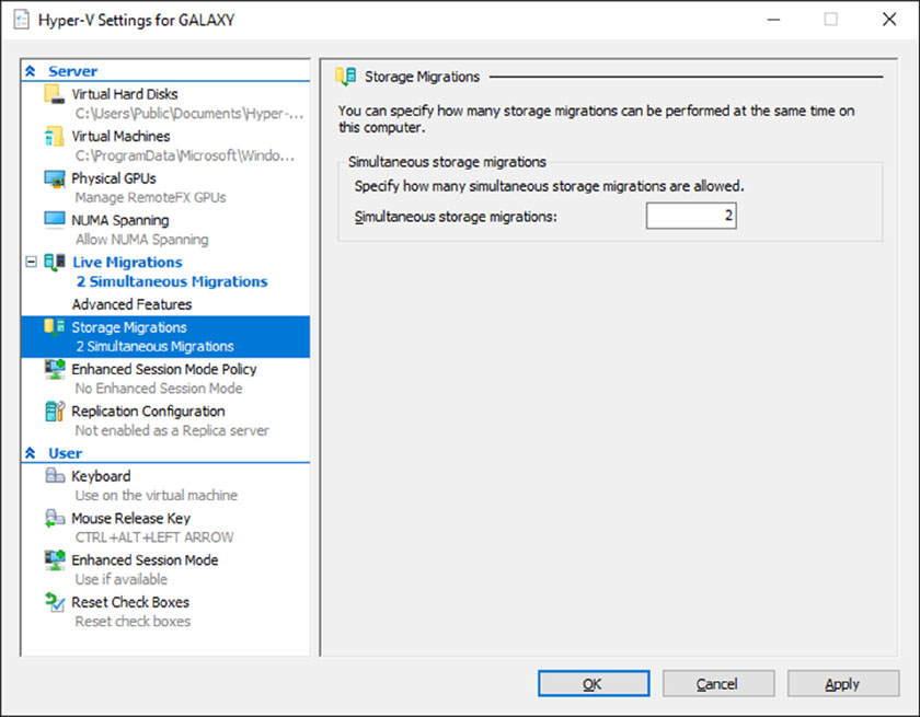
FIGURE 7.22 Storage Migration Settings
- Disk reads and writes utilize the source virtual hard disk.
- When reads and writes occur on the source virtual hard disk, the disk data is copied to the new destination virtual hard disk.
- Once the initial disk copy is complete, the disk writes are mirrored to both the source and destination virtual hard disks, while outstanding disk changes are replicated.
- After the source and destination virtual hard disks are entirely synchronized, the virtual machine changes over to using the destination virtual hard disk.
- The source virtual hard disk is deleted.
PowerShell Commands for Hyper-V High Availability
When configuring Hyper-V high availability, you may want to setup some of the components using PowerShell. Table 7.6 shows you some of the available PowerShell commands available for setting up Hyper-V high availability.
TABLE 7.6 PowerShell Commands for High Availability
| PowerShell Command | Description |
| Complete-VMFailover | This command helps finish a virtual machine’s failover process on the replica server. |
| Disable-VMMigration | This command allows an administrator to disable virtual machine migration on a virtual machine host. |
| Enable-VMMigration | This command allows an administrator to enable virtual machine migration on a virtual machine host. |
| Enable-VMReplication | This command allows an administrator to enable replication of a virtual machine. |
| Get-VMMigrationNetwork | This command shows you the virtual machine networks used for migration. |
| Get-VMReplication | This command shows an administrator the replication settings for a virtual machine. |
| Get-VMReplicationAuthorizationEntry | This command shows an administrator the authorization entries of a replica server. |
| Get-VMReplicationServer | This command shows an administrator the replication and authentication settings of a replica server. |
| Import-VMInitialReplication | This command imports initial replication files for a replica virtual machine when using external media. |
| Measure-VMReplication | This command shows an administrator the replication statistics and information associated with a virtual machine. |
| New-VMReplicationAuthorizationEntry | This command allows you to create an authorization entry to replicate data to a specified replica server. |
| Remove-VMMigrationNetwork | This command allows an administrator to remove a network from use in migration. |
| Remove-VMReplication | This command removes the replication from a specific virtual machine. |
| Reset-VMReplicationStatistics | This command allows an administrator to reset the replication statistics of a virtual machine. |
| Resume-VMReplication | This command allows an administrator to resume virtual machine replication after an error, a pause, a suspension, or a resynchronization is required. |
| Set-VMProcessor | This command allows an administrator to configure which processors are used for a virtual machine. |
| Set-VMReplication | This command allows an administrator to modify the replication settings of a virtual machine. |
| Set-VMReplicationServer | This command allows an admin to configure a host as a replica server. |
| Start-VMInitialReplication | This command starts replication of a virtual machine. |
| Stop-VMReplication | This command stops replication of a virtual machine. |
| Suspend-VMReplication | This command suspends replication of a virtual machine. |
| Test-VMReplicationConnection | This command allows an administrator to test the connection of a primary server and a replica server. |
Summary
High availability is more than just clustering. It is achieved through improved hardware, software, and processes. This chapter focused on how to configure Failover Clustering and Network Load Balancing in order to achieve high availability and scalability.
High availability should be approached through proper hardware configuration, training, and operational discipline. Failover clustering provides a highly available base for many applications, such as databases and mail servers.
Network load-balanced clusters are used to provide high availability and scalability for network-based applications, such as VPNs and web servers. Network load-balanced clusters can be configured with any edition of Windows Server 2016 except for the Windows Server 2016 Hyper-V Edition.
Windows Server 2016 Hyper-V can also have high availability set up on it without using clustering. Administrators have the ability to setup Live Migrations on Hyper-V virtual machines.
Live Migration allows you to move a virtual machine from one server to another without any impact on the users. This can be very useful if you have a Hyper-V server that is starting to show hardware issues. Administrators can move the virtual machine from the server with issues to a server without any issues.
Exam Essentials
Know how to modify failover and failback settings. These settings are set on the clustered service or application, but they can be modified by settings on the resources.
Know the hardware requirements for Network Load Balancing. Network Load Balancing has distinct hardware requirements. Know the requirements for NLB.
Know the PowerShell commands for NLB. Make sure you know the different PowerShell commands for Network Load Balancing. Understand which command is used to create, manage, and stop NLB clusters.
Understand Live Migration. Understand how Live Migrations work and why we use them. Understand that Live Migrations allow an administrator to move a virtual machine from one server to another without any impact on the users.
Know PowerShell for VM Replication. Make sure you know the different PowerShell commands for Virtual Machine Replication. Understand which commands are used to create, manage, and stop VM Replication.
Video Resources
There are videos available for the following exercises:
- Exercise 7.2
- Exercise 7.5
You can access the videos at http://sybextestbanks.wiley.com on the Other Study Tools tab.
Review Questions
-
You are the administrator for a mid-size organization. You have been asked by the owner to set up a NLB cluster. You want to use PowerShell to set up the cluster. What command would you use?
- New-NlbCluster
- Create-NlbCluster
- Setup-NlbCluster
- Set-NlbCluster
-
Which of the following editions of Windows Server 2016 can be configured in a Network Load Balancing cluster? (Choose all that apply.)
- Windows Server 2016 Virtual Edition
- Windows Server 2016 Standard Edition
- Windows Server 2016 Small Business Server
- Windows Server 2016 Datacenter Edition
-
What is the maximum number of nodes that can participate in a Windows Server 2016 NLB single cluster?
- 32
- 4
- 16
- 64
-
Which of the following actions should be performed against an NLB cluster node if maintenance needs to be performed while not terminating current connections?
- Evict
- Drainstop
- Pause
- Stop
-
Which of the following actions should be performed against an NLB cluster node if maintenance needs to be performed and all connections must be terminated immediately?
- Evict
- Drainstop
- Pause
- Stop
-
You are the network administrator for your organization and you want to stop virtual machine replication. What PowerShell command would you use?
- Stop-VMReplication
- Terminate-VMReplication
- Kill-VMReplication
- Drainstop-VMReplication
-
Which of the following applications would be better suited on a Network Load Balancing cluster instead of a failover cluster? (Choose all that apply.)
- SQL Server
- Website
- Database servers
- Terminal Services
-
To configure an NLB cluster with unicast, what is the minimum number of network adapters required in each node?
- One
- Two
- Three
- Six
-
Users who are connecting to an NLB cluster have been complaining that after using the site for a few minutes they are prompted to log in using their username. What should you do to fix the problem and retain scalability?
- Create a port rule to allow only ports 80 and 443.
- Set the cluster affinity to None.
- Set the filtering mode to Single Host.
- Set the cluster affinity to Single.
-
Users who are connecting to an NLB cluster through the Internet are complaining that they keep connecting to different NLB nodes in different locations. You want to keep Internet users connecting to the same NLB members each time they connect. What should you do to fix the problem?
- Create a port rule to allow only ports 80 and 443.
- Set the cluster affinity to None.
- Set the cluster affinity to Class C.
- Set the cluster affinity to Single.