Chapter 20. Flying the S500
We have put all the pieces in place. We’ve done some testing. Hopefully, you have even gained some understanding of how it all works. But there comes a time in the development of any aircraft when you just have to take off and see how it goes.
Next, we will install the props and talk for a moment about prop choice. At this point the drone will look something like Figure 20-1. Then we will strap on a battery and backup power meter.

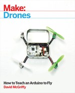
Figure 20-1. The completed large drone stands ready to fly
The systems will demand some calibration before being willing to fly. We did the magnetometer in the previous chapter, but we must still do the radios and accelerometers. You can choose which flight modes you want for which switch positions, and then, of course, there’s tuning.
If you have built something close to the design shown, then you can simply load the tuning parameters I use from www.makedronesbook.com/projects/S500. If you have made any important changes, like frame size or motor specs, then you might be better off starting with the default settings and tuning it yourself.
Install the Props
For initial flight testing, we’ll use the nylon 1045 props that commonly come with motors in this size range. You can get them from multiple sources for a reasonable price, and they work quite well. These props don’t come perfectly balanced, however, so I strongly advise following the prop balancing procedure outlined in Chapter 22.
Don’t Use Carbon Fiber Props for Testing
Carbon fiber props are lighter, thinner, stronger, more efficient, and, perhaps most important, really cool looking! So why not use them on your shiny new drone? They also spin a bit faster and are sharp as razors. Until you have confidence in your drone and your ability to fly it, make the world a little safer and use plastic props.
The EMax motors we’re using can accommodate traditional props with a hole all the way through, or DJI-style self-tightening props that screw on directly. The traditional props we’re using, shown in Figure 20-2, require that you choose the right adapter ring from the provided set. Find the smallest one that fits over the motor shaft. Now, go balance them!
When installing props on the motors for flight, the adapter ring side goes down. Figure 20-3 shows the proper direction, clockwise or counterclockwise, for each prop. If in doubt which way a prop goes, just spin it around a bit and visualize which way pushes the air down. The different color prop nuts match the different directions, black for clockwise and silver for counterclockwise.

Figure 20-2. These generic 1045 plastic props require adapters to fit on motor shafts

Figure 20-3. Be sure your props spin in the right direction before flight
You want the prop nuts on pretty tight, of course. It’s obviously bad if one comes off in flight! But the thread direction for each motor causes the nuts to tighten rather than loosen with the force of the motor. And if you put too much force on the prop hub, it can crack. I tighten mine using no more than an inch or so of wrench length. If you pushed hard at the end of a six-inch wrench, you would crack them easily.
Connect the Battery and Voltage Monitor
Depending on what other payload you strap to it, this drone could carry a very large battery. I’ve done my flight testing with 3S, 2,700 mAh batteries (Figure 20-4), mostly because I already had several. This will be our first time to step up from 1S or single-cell batteries to 3S batteries that have three cells in series.

Figure 20-4. These 2,700 mAh, 25C battery packs worked well for flight testing
According to a chart from the manufacturer, the EMax 2216 motors with 1045 props and 3S batteries can draw nearly 10 amps. Rounding up to 10, times 4 motors, gives us 40 amps total current. If you divide this by the 2.7 Ah rating of our battery, you get just less than 15C. My packs are rated for 25C, so I have been fine. If you want to try anything smaller, do the math and make sure your battery can provide at least 40 amps, hopefully with a bit of margin. Anything with a larger mAh or C rating will be fine as long as you don’t run it down too far—which is why you’ll want a voltage monitor.
For something less than five bucks, you can buy a small digital voltage meter (Figure 20-5) with an alarm that plugs directly into the balance plug—the small white one—from the battery. This way it can monitor each cell individually and warn if any one goes below a set limit.

Figure 20-5. A cheap voltage monitor could save your drone
Attach the battery monitor to the battery with the black or ground wire on the left side (check your unit to make sure this is correct, though; it should have some kind of instructions on the back side). When properly attached, the LEDs will display first the total voltage, then the voltage of each cell. If any cell goes below the limit an amazingly loud alarm sounds—loud enough that you can hear it over a powerful drone at a distance.
The limit can be changed using a small button on the top of the unit. I set mine at 3.7 volts. This gives me enough flight time and leaves the battery at right about the storage voltage of 3.75V (the voltage dips a bit under load, so the final resting voltage will be a bit higher).
I installed my voltage monitor by putting a wire tie around one of the mounts that hold the battery to the tubes. Having a bit of play left makes it easier to get the balance plug connected to the unit. You can see the results in Figure 20-6.

Figure 20-6. The voltage monitor must be installed close to the battery connector
The power adapter we installed earlier reports voltage and current to the flight controller, and we can also use telemetry to connect to a smartphone to give us low voltage warnings. It’s a pretty cool system, but there are lots of ways it can go wrong. If you always plug in that backup voltage monitor, your $5 investment may well save a $50 battery!
Radio and Accelerometer Calibration
The APM flight stack won’t let you arm the motors until you have finished certain setup tasks. We did the compass calibration previously, while discussing how magnetometers work. You must also calibrate the radio and accelerometers.
In the days before it was practical to put computers in our model aircraft, advanced RC pilots would use complex transmitters that could save settings for multiple models. Today, the computer in the model can be set to respond correctly to a standard transmitter. All it needs to know are the minimum and maximum values that your transmitter puts out on each channel, since these vary a bit from one transmitter to another. Knowing exactly what “all the way down” translates to matters for actions like arming. I like QGroundControl’s calibration screens the best, so Figure 20-7 shows that radio calibration screen.

Figure 20-7. Radio calibration tells the flight controller about your transmitter
If calibrating the compass is a dance, then perhaps calibrating the accelerometers is the rehearsal. We go through the same basic positions, but instead of twirling around, we just hold still in each one. Figure 20-8 shows this calibration screen in QGroundControl.

Figure 20-8. Accelerometer calibration lets the controller know which way is down
Flight Modes
Strictly speaking, setting flight modes isn’t required. By default in APM all switch positions translate to stabilize mode, which is a fine place to start. But this drone can do so much more! In order to access other modes, we have to map the positions of the channel 5 rotary switch on the transmitter to different modes. The Quanum i8 transmitter outputs values that map perfectly to the default ranges in APM, so we just have to choose which modes to use.
I’ve mapped the six positions on my transmitter to stabilize, altitude hold, loiter, position hold, auto, and return to land, as you can see in Figure 20-9. This makes a useful sequence since I generally take off in stabilize, which requires the least number of sensors, then go to altitude hold, which adds the barometer; only if that seems be working well do I use any of the last three modes, which all require GPS.

Figure 20-9. The default PWM ranges matched our transmitter, making setup easy
Initial Tuning
I’ll be honest. I figured that this was a pretty typical setup, and I’ve tuned enough drones to at least my own satisfaction by now that this one should go easy. Nope. The first time I hit the throttle, it flipped on its back with amazing speed, shattering one prop. OK, I had two motors plugged in backward. But the tuning still took many flights. I believe that one factor was doing testing with a small battery and no payload—that is to say, lighter than I will probably fly most of the time. This meant I was dialing back from twitchy instead of turning it up from sluggish. Not conceptually harder, but it kept my heart rate up and I broke a few props.
The APM flight system used here, version 3.3.3, does respond very nicely to being well tuned. For this work I prefer the extended tuning screen in Mission Planner ground control station. There must be a dozen different P or PID controllers that can be adjusted. But it turns out that you usually only have to adjust the core PID controllers for the roll and pitch rates, and the rest will all fall into place. For those key values, I am currently flying at 0.11, 0.00, 0.004. Since this quad is symmetrical, roll and pitch are the same, as seen in Figure 20-10.

Figure 20-10. The extended tuning screen in Mission Planner is well organized
Final Checklist and First Flight
Consider carefully where to do your first flight testing with any drone this size. Unlike our previous projects, this one can dent cars, break windows, or hurt people if it gets out of control. A large, unobstructed place with no other people around would be best, but few of us have acess to an ideal location, so do the best you can. Working in a small space with nothing but brick walls to hit might be bad for your drone but safer for the world. When in doubt, err on the side of safety.
Next, consider the weather conditions for your first flights. A dead calm would be best. Try to notice what time of day tends to have the least wind in your area. You might also check the space weather at a site like www.uavforecast.com to make sure nothing funny happens to your GPS signals.
With time and place chosen, prepare the drone:
- Check for any unplugged cables or loose parts.
- Check the props for damage or missing balance tape.
- Turn on your transmitter and make sure the throttle is all the way down, with the mode set to stabilize.
- Strap on a battery, connect it to the voltage monitor, and check that you have enough power to fly, around 12.5 volts total.
- Check the polarity and plug the battery into the main XT60 connector.
- (Optional) Connect to the telemetry via your smartphone or computer and check the status.
- Wait for a 3D GPS lock and an HDOP of less than 2 (ideally close to 1).
- Check that the area is clear and arm the motors by holding the left stick down and to the right.
- Slowly raise the throttle. The motors should all start.
Raise the throttle more, and you will fly! If the drone flies well in stabilize mode, then stay there. I find this one much easier to hover in altitude hold, but staying in stabilize requires the least number of sensors to be working right. This is where piloting skill really pays off. Time spent flying the smaller drones will make you more confident with this one.