Chapter 17. Install the Flight Controller and Radios
We’ve put in the muscle. Now it’s time to add the brains (and, I suppose, the eyes, ears, and mouth, to stretch the analogy a bit). More seriously, we are going to mount a Pixhawk Lite flight controller, a GPS receiver, the RC receiver, and the telemetry radio, then wire them all up. Oh, and a safety button—another new feature very appropriate to a larger, more powerful drone. Figure 17-1 shows these components wired together, but not installed.

Figure 17-1. The central Pixhawk Lite controller with three radios and a power module
I got all of these components, except for the RC radio, in a single kit, but they can also be bought separately. We’ll discuss each part in more detail as we install them. When we are done, this will complete the first round of hardware installation on the big drone. We still have a couple of chapters to go before we properly understand all this new hardware, but once we do this, it will be a very capable drone. Among other things, this drone will be able to fly itself. Using GPS and a compass, it will be capable of following a series of waypoints in fully autonomous flight!
Pixhawk Lite and Shock Mount
To make sure we have power for future expansion, we will put a 32-bit Pixhawk Lite flight controller in this drone. The Lite version of this controller eliminates a few connectors that few people use in favor of being smaller, lighter, and cheaper.
When last we left our drone, we had installed only the bottom plate, with the ESC power and battery connector attached. Push the battery connector down through the large hole in the back of the bottom plate. Plug a six-pin signal cable into the power module, then plug the power module into the end of the battery connector. Push the signal cable up through the hole where the battery connector comes down. Arrange everything as neatly as you can and wire-tie the parts in place so they won’t move when flying around, or especially when disconnecting a battery. The results should look something like Figure 17-2.

Figure 17-2. A close-up showing how the power module fits below the bottom plate
One thing included in many flight controller kits, though not the one I got, is a shock mount. This mount provides some level of vibration isolation between the controller and the motors. As we will cover in detail in Chapter 22, more powerful motors can create more vibration and more sophisticated flight controllers can be more sensitive to vibration, so shock mounts become important as drones get larger.
We’re ready to mount the top plate, so bring all the ESC signal cables and the signal cable from the power module up through the big hole in the middle of the top plate and screw it into place. Now, using double-stick foam tape, place the shock mount back against the hole where the ESC cables come up. You can see the correct placement in Figure 17-3.

Figure 17-3. The shock mount should be placed up against the large hole in the top plate
Using more double-stick foam tape, place the controller on top of the shock mount with the pins facing to the rear. Be careful to align the controller as well as possible since this is where the drone gets its sense of up and forward, though the firmware can compensate for small errors. Now route the cable from the power module up through the center hole in the top plate and plug it into the port on the left side of the flight controller, as seen in Figure 17-4.

Figure 17-4. The power module plugs into the left side of the Pixhawk Lite
RC Radios
I chose the Quanum i8 (Figure 17-5) radio control transmitter and receiver for this drone. Almost any system with five or more channels will work, but I like this set because it has some features designed specifically with drones in mind. Like with nearly all RC aircraft transmitters, the first four channels contain roll, pitch, throttle, and yaw, though not necessarily in that order.

Figure 17-5. The mode lights at the top center of this Quanum i8 transmitter suit drones perfectly
Many flight control systems use channel 5 for mode control, and the Quanum i8 transmitter handles this perfectly. There is a rotary knob with LEDs that show the positions. It even comes with stickers to label the different modes. Regrettably there is no PosHold sticker, since position and hold mode works very well on this quadcopter.
The Quanum i8 receiver has eight of the standard three-pin pulse width modulation (PWM) outputs that can directly drive servos or ESCs. In another feature that supports drones well, the receiver also sends all eight channels out on a single output using combined pulse position modulation (CPPM, or just PPM). This allows us to connect the receiver to the flight controller with a single servo cable, which also serves to provide power to the receiver.
Place the receiver on the top plate, to the right of the controller, using double-stick foam tape. The pins should face to the rear, the same as the controller. Run a three-pin servo cable from the leftmost port of the receiver to the rightmost port on the controller as seen in Figure 17-6. You can also plug the ESC signal cables into the controller at this point, but be careful: the outputs on the controller start with channel 1 in the middle, not on one end as you might expect. Figure 17-7 shows how the motors are numbered.

Figure 17-6. The Pixhawk Lite outputs don’t start where you might expect them to

Figure 17-7. Motor numbering for the Pixhawk flight controller
On the other end of the RC receiver, two antennas come out. With two antennas, one will hopefully continue getting a good signal when the other gets interference. I routed these down through the slot in the front of the top plate and then replaced the heat shrink on the forward ESCs to include them. This keeps them out of the way, as seen in Figure 17-8.

Figure 17-8. Putting the RC antennas in the heat shrink keeps them safe
Telemetry Radio
For telemetry, we will use a 3DR 433 MHz radio set. These are widely available, fairly cheap, and easy to interface to an APM- or PX4-based flight controller. Note that use of the 433 MHz band in the US requires a ham radio license.
We can actually do much more than just telemetry (i.e., real-time monitoring of flight information) with this radio. Basically, this link can do anything a USB link can do, though it’s not as fast. This includes setting turning parameters, creating autonomous flight plans, and even sending commands like “start the programmed mission,” or “return to land.”
The telemetry radio comes with several cables. The one attached to it includes a split to send the telemetry data to the on-screen display (OSD) that will add information to the video downlink. We don’t need this now, but we might later. One end of each cable will fit the telemetry radio. Find one where the other end fits the telemetry port on the side of the flight controller. Now check the cable wiring very carefully to verify that it looks like Figure 17-9.

Figure 17-9. Verify the cable wiring before powering up the system
Safety Switch
To complete this chapter, we will install the safety switch. When preparing for flight, you must press and hold this switch for several seconds before the motors can be armed. This ensures that no single action on the RC transmitter or via telemetry can accidentally arm them. As drones get larger and more powerful, it becomes increasingly important to guard against spinning props. In addition to the safety switch, we must always take the time to remove the props when not required for testing and make sure the area is clear before allowing a prop to spin.
Wiring the safety switch just means wire-tying the switch itself to the bottom plate as shown in Figure 17-10, then routing the cable up through both plates and plugging it into its port, as seen in Figure 17-9.

Figure 17-10. Secure the safety switch to the bottom plate with wire ties
Testing
Let’s stop and test what we’ve just installed before going any further. First, plug the controller into your computer via USB. You should get blinking lights on both the telemetry radio and the RC radio. (And no smoke!) If you don’t see a good response, immediately unplug the system. You might save a component that has its power wired backward if you’re quick!
Next try powering the system from a battery. Unplug the USB and plug in a charged, 3S lithium polymer (LiPo) battery pack and you should get the same response you got previously, though you might also get some beeps from the ESCs since they are getting power now too. If the USB test worked and this one didn’t, check the cable between the power module and the controller.
Leaving the quadcopter powered up, plug the telemetry ground unit into a USB port on your computer. The light inside should come on and within a few seconds this light and the one in the telemetry air unit should both stay on constantly, meaning that they have established a link. You can now start up your favorite MAVLink ground station software and connect to your drone.
Personally, I don’t have an overall favorite. I use a combination of Mission Planner, QGroundControl, APM Planner (Mac), and finally Tower on my smartphone. QGroundControl has the slickest interface. It connects automatically in most cases, which really helps, and it has great calibration screens for both accelerometer and compass. And it runs on both Mac and Windows.
MissionPlanner only runs on Windows, but it has a built-in log viewer that I’m used to and puts all the PID tuning parameters on one very useful screen. I also tend to use MissionPlanner for, well, planning missions (that is, creating autonomous flight plans). QGroundControl also does a good job of this so my choice is mostly habit.
I use APM Planner, which is Mac only, just for its compassmot. It produces a nice graph while it’s running that lets you see how good the data is. I use the Tower application when running on a smart phone. Using a small USB adapter, it will connect to the telemetry dongle. I always keep this turned on when flying, though my phone often sits in my pocket, just giving audio feedback on modes, battery state, and altitude.
At the moment, the point is only that the radio calibration screen in Mission Planner makes a nice radio test. I recommend looking at the connection drop-down before and after connecting the telemetry receiver so you can see which port got added. Select that port and a baud rate of 57,600 and it should connect up. Once it finishes reading all the parameters you can switch to the Radio Calibration screen in the Initial Setup category and the graphics should respond to the controls on your RC transmitter (see Figure 17-11).
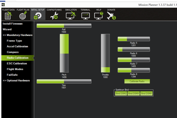
Figure 17-11. Mission Planner’s Radio Calibration screen is a good test of the RC radio
This completes the installation of everything we are going to wire up on the top plate, so go around the system and wire-tie everything down. I found that the unused mounting holes on the corners of the shock mount made good tie points. Shake your drone around a little. Does anything move too much? If so, reroute or use more wire ties. Their weight won’t matter this time.
Two radios installed so far, and one more to go. In the next chapter we will install a GPS receiver and I’ll explain a bit about how it works.