
Chapter 11. Heating and Cooling
This chapter explores devices for generating heat and also cooling. This includes resistive heater elements and Peltier elements.
This chapter focuses on how heaters and coolers work. In Chapter 12 we will use the heating and cooling devices described here with Arduino and Raspberry Pi for precise thermostatic control.
Resistive Heaters
Back in Chapter 5, we touched on the fact that in the process of restricting the flow of current, resistors generate heat. As you might recall, the amount of heat generated in watts is the current in amps flowing through the resistor multiplied by the voltage drop in volts across the resistor.
Experiment: Resistor Heating
You should now be familiar with simply turning power on and off to start a motor. Exactly the same principles apply when switching the power to a resistor. Any of the previous experiments that have controlled the power to a motor will work equally well with a resistor. Even using PWM to control the power will work just as well with a resistor heater. So, to carry out this experiment, you can dispense with your Arduino or Raspberry Pi and just make do with a battery pack and a resistor.
Note that this project uses a resistor as a heating element and a battery as a power source. Neither of these choices are very practical unless you are heating something very small. They are, however, very convenient for experimentation.
Parts List
You will need the following parts to try out this experiment:
| Part | Sources |
| 100Ω resistor | Mouser: 291-100-RC |
| Thermometer |
Hardware store |
| 400-point solderless breadboard | Adafruit: 64 |
| 6V (4 x AA) battery box | Adafruit: 830 |
Construction
In this project, you are really just connecting the resistor across the battery terminals and using the breadboard to hold the resistor in place, as shown in Figure 11-1.

Figure 11-1. Resistive heating experiment
Don’t attach the battery just yet, because as soon as you do, the resistor is going to get hot.
Experimenting
Connect the battery box, and use your thermometer to measure how quickly the temperature rises on the resistor. The resistor temperature will probably get up to about 170° F (75° C), so watch out—that’s hot enough to burn your finger!
The resistor is 100Ω and the voltage 6V, from which we can calculate the current as I = V / R = 6 / 100 = 0.06A. The power is the voltage multiplied by the current, which is 6 x 0.06 = 0.36W, or 360mW.
That’s a little more than the resistor’s maximum power rating of 250mW (1/4W), so the resistor may fail after a while.
Project: Arduino Random Balloon Popper
This is not a project for the balloon-phobic. It uses an Arduino to control a resistor as a heating element that is taped to a balloon and after a random period of time, the resistor is powered up and pops the balloon (Figure 11-2).

Figure 11-2. A random balloon popper
This is a fairly destructive project, as to get the resistor hot enough to pop a balloon also means making it hot enough to damage itself—you are quite likely to see some smoke.
Parts List
You are going to need the following parts to build this project:
| Name | Part | Sources |
| R1, R3 | 470Ω resistor | Mouser: 291-470-RC |
| R2 | 10Ω 1/4 W resistor |
Mouser: 291-10-RC |
| Q1 | MPSA14 Darlington transistor | Mouser: 833-MPSA14-AP |
| LED1 | Red LED |
Adafruit: 297 Sparkfun: COM-09590 |
| 400-point solderless breadboard | Adafruit: 64 | |
| Male-to-male jumper wires | Adafruit: 758 |
You should get several 10Ω resistors, as these are likely to literally go up in smoke.
Hardware
By the time the Darlington transistor has taken its share, there will be about 3.5V across the resistor when the transistor turns on. This means a current of 3.5V / 10Ω = 350mA. This should not overload any USB device powering the project.
The heat power coming from the resistor will be I x V = 350mA x 3.5V = 1.225W. This is a lot more than the 1/4W that the resistor is rated at, but the resistor should survive long enough to burst the balloon.
Figure 11-3 shows the breadboard layout for the project.
The resistor should be firmly attached to the jumper wire pins (Figure 11-4), so that it does not come adrift when the balloon pops.

Figure 11-3. The breadboard layout for the balloon popper

Figure 11-4. Making a resistor lead
Software
There is no start button for this project apart from the Arduino’s Reset button. The Arduino sketch for this project starts as soon as it’s plugged in, so you should keep one of the jumper wires to the resistor disconnected until you are ready to do some popping.
Go to /arduino/projects/pr_balloon_popper (which you’ll find in the place where you downloaded the book’s code):
constintpopPin=11;constintminDelay=3;// SecondsconstintmaxDelay=5;// SecondsconstintonTime=3;// Secondsvoidsetup(){pinMode(popPin,OUTPUT);randomSeed(analogRead(0));longpause=random(minDelay,maxDelay+1);delay(pause*1000);digitalWrite(popPin,HIGH);delay(onTime*1000);digitalWrite(popPin,LOW);}voidloop(){}

-
The constants
minDelayandmaxDelayspecify the range of possible times after which the resistor will be powered up and the balloon might pop. 
-
The constant
onTimespecifies how long the resistor needs to be on. You may need a bit of trial and error to get this right. You don’t want the resistor to be hot for too long, or it will quickly burn out. 
-
Random numbers in Arduino C are not truly random, but actually part of a long sequence. To ensure that you get a different delay each time your Arduino restarts, this line sets the position of that sequence based on the reading on analog pin A0. Since this pin is not connected to anything, the readings from it are more or less random.

-
The pause before the resistor gets switched on is decided by the
randomfunction that returns a random number between the two values supplied to it as parameters. 1 is added to the second parameter because the range is exclusive. The variable used is of typelongbecause anintcan only hold numbers up to 32,767, which would stop you specifying a range of possible delays beyond 32 seconds. 
-
Delay for
pauseseconds. 
-
Turn on the transistor and power up the resistor. Delay for
onTime()then turn the power off again.
Using the Balloon Popper
While you are testing the project, you might want to add a bit of certainty as to when the balloon is going to pop, so change minDelay and maxDelay to perhaps 2 and 3, respectively.
Tape the resistor to the balloon and then plug the resistor leads onto the breadboard. Click the Reset button and wait for the bang.
Heating Elements
Resistors are not really very practical as heaters. To heat anything of any size, you would use a heating element. Heating elements are really just big resistors made from materials that are designed to get hot and also to transfer that heat into whatever you are trying to make hot.
Heating things up generally requires a lot of energy in comparison with generating light, sound, or even movement. So, heating elements for things like electric kettles, domestic washing machines, and other appliances that heat water will use high-voltage AC direct from the AC line to simply get enough power to do the job. As such, when switching substantial heating elements, you will probably need to look ahead at Chapter 13.
The power of a heating element is measured in watts (W) or kW (thousands of watts) just like the power ratings of a resistor. It’s really the same thing. The power rating of the resistor is just the amount of heat energy it can produce per second before it gets too hot and breaks.
In “Experiment: Resistor Heating”, we used Ohm’s law and the power law (P = I V) to calculate the power. These can be combined into a single useful formula that will tell you the power if you know the resistance of the heating element and the voltage across its terminals:
![]()
In other words, the heat power produced by a heating element is the voltage squared in volts divided by the resistance in ohms. This formula is true for both DC and AC voltages.
As an example, a 10Ω resistor (or heating element) with 12V across it will generate (12 x 12) / 10 = 14.4 W of heat. If the voltage was 120V AC, then the power would be (120 x 120) / 10 = 1440W or 1.44 kW.
So, any heating element should have a couple things defined for it:
- Its working voltage (12V, 120V, 220V)
- Its power (50W, 1kW, 5kW)
If it’s a heating element designed to heat water, it probably needs to be in water, so that the water can carry away the heat. If not, it may quickly become too hot and burn out.
Power and Energy
The words power and energy are often used interchangeably in general language. Scientifically speaking, the relationship between power and energy is as different as the relationship between speed and distance.
Power is actually the rate of conversion of energy. The power of a heating element is the amount of energy that is released as heat per second.
The unit of energy is the joule, and a watt of power is actually one joule of energy per second.
From Power to Temperature Increase
If you know how many watts of power your heating element can produce and the material it is heating, you can work out how long it will take to increase the temperature by a certain amount.
As with many things of a scientific nature, the international units of watts, degrees Celsius, grams, and seconds tend to be used for these calculations. You can always convert your answer into a unit you are more familiar with later.
Materials have a property called specific heat capacity (SHC). This is the amount of energy it takes to raise one gram of the material by 1°C. For example, water has an SHC of 4.2 J/g/degree C. In other words, it takes 4.2J of energy to raise 1 gram of water by 1°C in temperature. If you wanted to raise 100 grams of water by 1°C, it would require 420J of energy, and if you wanted to raise that same 100 grams by 10°C, the energy requirement would go up to 4200 joules.
Air has an SHC of around 1 J/g/degree C, and glass has an SCH of around 0.8 J/g/degree C. All materials are different.
Boiling Water
As an example, let’s work out how well our little resistor would do at boiling some water.
Let’s assume that we want to boil a cup of water (about 250g of water). Let’s also assume that the water starts at room temperature (20°C) and will boil at 100°C; this means there is a temperature increase of 80°C.
The total energy needed to raise this 250g of water by 80°C is:
4.2 x 250 x 80 = 84,000 joules
In “Experiment: Resistor Heating”, your resistor was producing 0.36W or 0.36 joules per second. So, at that rate, it would take 84,000 / 0.36 = 233,333 seconds, which is roughly 64 hours!
For practical reasons described in the next section, it’s never actually going to get there.
Peltier Elements
Peltier elements (Figure 11-5) have the very useful property that when you pass a current through them, one side of the element gets hotter and the other cooler.
You have to use a fair amount of current for this to happen (typically 2 to 6A at 12V), so to use a Peltier element you will need a fairly beefy power supply. These elements are often found in camping fridges and beverage coolers, and have the advantage over conventional refrigerators of having no moving parts to go wrong.
How Peltier Elements Work
When a current passes through a junction between two different conductive materials, one side of the junction will get slightly hotter and the other slightly cooler. This is called the Peltier effect after the French physicist Jean Peltier who discovered it in 1834. It is also known as the thermoelectric effect.
The effect is relatively small, so to make it useful enough to do something like cool down a beverage for us, the effect needs to be multiplied. This is accomplished by placing a series of alternating junctions next to one another so that current can pass through each one in series, so that each contributes to the overall effect. Common, low-cost elements typically have around 12 junctions (Figure 11-6). On either side of the elements there is a base material that forms the bread of a junction sandwich.

Figure 11-5. A Peltier element
The different types of material used in the junctions are two types of semiconductor, like those used to make transistors and chips, but optimized for their thermoelectric effect. They are known as N or P type (negative and positive).
One very interesting feature of Peltier elements is that as well as being used to cool things, if you arrange for one side to be hotter than the other a small amount of electricity is generated.
Practical Considerations
The main problem with Peltier elements is that the hot and cold sides are very close together and so the hot side will soon warm the cold side unless something is done to take the heat away as quickly as possible.
The starting point for this is to use a heat sink, as shown in Figure 11-7.

Figure 11-6. Inside a Peltier element
In the cooling unit shown in Figure 11-7, the heat sink is a lump of aluminum with blades sticking out to increase the surface area and carry away the heat. The cold side of the unit is the block arrangement that is designed to protrude into the thermally insulated refrigerated compartment.
A heat sink on its own is not nearly as effective as a heat sink with a fan attached to it to take away the air that has been warmed by convection and replace it with new cooler air. In fact, some units have a fan on both sides of the Peltier element to help it work more efficiently (Figure 11-8).
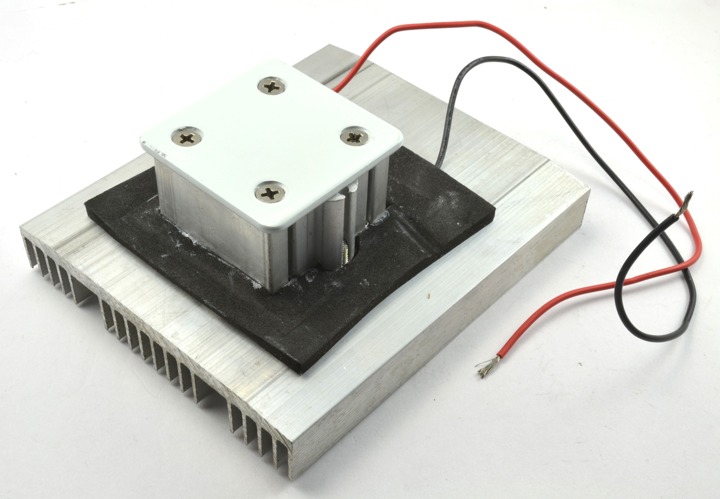
Figure 11-7. Using a heat sink with a Peltier element

Figure 11-8. A Peltier refrigeration unit with dual fans
Project: Beverage Cooler
This project does not use either a Raspberry Pi or an Arduino, but really just serves to show you how to wire up a Peltier cooling unit and how you can make yourself a simple beverage cooler (Figure 11-9). In Chapter 12, this basic project will be extended to add thermostatic control of the temperature, and then in Chapter 14, it will get an OLED display to indicate the temperature.

Figure 11-9. The drinks cooler project
Parts List
You are going to need the following parts to build this project:
| Part | Sources |
| Dual-fan Peltier refrigeration unit 4A or less | eBay |
| Female barrel jack to screw terminal adapter | Adafruit: 368 |
| Power supply (12V at 5A) | Adafruit: 352 |
| Large milk or juice container |
Recycling |
| A refreshing drink |
If you want to use a more powerful Peltier element than 4A, make sure that you also upsize your power supply to have a higher maximum current rating than the cooling unit. Allow at least an extra half amp for the fans and half an amp for luck.
Construction
If you unravel the wires of your cooling unit, you will find three pairs of wires: one pair for the Peltier element itself and one pair for each of the two fans. All of these require 12V from the power supply and the easiest way to accomplish this is to use a handy screw terminal to DC barrel socket adapter. Simply put all three red wires from the cooling unit into the screw terminal marked + and all three black wires into the screw terminal marked—as shown in Figure 11-10.

Figure 11-10. Wiring the beverage cooler project
You’ll need to cut off the top of the plastic container and cut a square aperture into the side so that the cooling part of the Peltier cooling unit sticks into the bottle (Figure 11-11). Make sure to choose a plastic container that is large enough to contain your favorite glass or bottle for cooling.

Figure 11-11. Adapting the plastic container
If the cool-side fan has screws that protrude, make a couple of holes in the plastic container for them too, so that the cooling unit is firmly attached to the plastic container. If you make sure that the hole for the cool-side of the Peltier unit is in the right place for the bottom of the Peltier cooler and plastic container to be level, then it won’t topple over.
The great thing about using a plastic container that would otherwise be recycled is that if you make a cut in the wrong place, you can always just start over with a new container.
Using the Project
With everything assembled, plug in the power supply and both fans should start to whir. If you put your hand into the container, you should immediately feel the cold air coming from the small fan.
As we discovered with our calculations on trying to boil water, changing the temperature of even a relatively small amount of water takes a long time, so although this project will eventually cool down a warm drink, it is far better at keeping a drink cold that was cold to start with.
This project is also somewhat wasteful, as it uses up to 50W of electricity just to keep one drink cool. In Chapter 12, you can make this project a bit more efficient and add thermostatic control to it.
Summary
Heating and cooling require quite high power to work quickly, but the switching techniques using transistors and relays can all be used to switch heating and Peltier elements.
In the next chapter, you will learn how to control temperature precisely and improve the beverage cooler project to use thermostatic control.